1
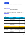
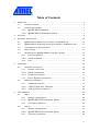
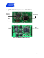
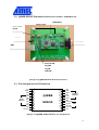
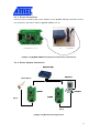
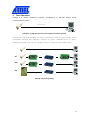
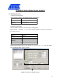
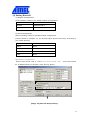
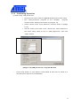
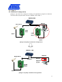
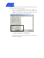
@Web SEG32 Serial-to-Ethernet Gateway Module User’s manual Version 2.0A DOCUMENTATION & TECHNICAL SUPPORT Product Ordering Information: ATWebSEG-32 E-Mail: [email protected] Web Site: www.atmel.com COPYRIGHT NOTICE W iznet Setup Tool of @Web SEG32 : IGM7100 For more information on Hardware TCP/IP, visit Wiznet website at http://www.wiznet.co.kr Copyright 2002 W IZnet Inc. All Rights Reserved @Web Hardwired Ethernet Product Derivatives Development Kits @Web LAN51H Description Ordering Information Development Kit For Ethernet Connectivity ATW EBDVK-02 with Hardwired TCP/IP @Web LAN51H RC Remote Control Application with Ethernet ATW EBDVK-02RC Connectivity @Web LAN51H W C Network Web Camera Application with ATW EBDVK-02W C Ethernet Connectivity @Web LAN51H VOIP Voice Transmission Application with ATW EBDVK-02VOIP Ethernet Connectivity Modules and Evaluation Kits Description Ordering Information @Web SEG32 Serial to Ethernet Gateway Module ATW EBSEG-32 @Web CEG32 CAN to Ethernet Gateway Module ATW EBCEG-32 @Web SEG32 EVK Evaluation Kit for Serial Ethernet ATW EBEVK-05 for CAN to Ethernet ATW EBEVK-06 to Gateway Module @Web CEG32 EVK Evaluation Kit Gateway Module Table of Contents 1. Read First ......................................................................................................... 7 1.1. Product Contents.................................................................................. 7 1.2. Product Specification ............................................................................ 7 1.2.1. @WEB SEG32 Module ................................................................ 7 1.2.2. @WEB SEG32 Evaluation board ................................................ 7 2 Overview ........................................................................................................... 8 3 Hardware Specification .................................................................................... 10 3.1. @WEB SEG32 Module (Part number: ATWebSEG-32) ......................... 10 3.2. @WEB SEG32 Evaluation board (Part Number: ATWebEVK-05) ........... 11 3.3. Pin Assignment and Dimension ............................................................ 11 3.4 Memory map ...................................................................................... 14 3.4 Miscellaneous (@W EB SEG32 Evaluation board) ................................ 14 3.5.1. Ethernet Interface ........................................................................ 14 3.5.2. Serial Interface .......................................................................... 15 3.5.3. 4. LED ............................................................................................. 15 Installation ...................................................................................................... 16 4.1. Hardware Connection ......................................................................... 16 4.1.1. Network connection ..................................................................... 16 4.1.2. Serial Connection ...................................................................... 16 4.1.3. Power Connection ..................................................................... 17 4.1.4. 4.2. Entire System Connection ........................................................ 17 Software Installation ........................................................................... 18 4.2.1. Installation Process...................................................................... 18 4.2.2. “IGM_Cfgtool.exe” Features ..................................................... 22 4.2.3 5 Test Operation................................................................................................. 27 5.1 5.2 “ IGM_PCutil.exe” Features ........................................................... 25 Step 1 ................................................................................................ 28 5.1.1 Network configuration .................................................................. 28 5.1.2 @WEB SEG32 Environment Setup .......................................... 29 5.1.3 Confirming Operation ................................................................... 35 Step 2 ................................................................................................ 37 5.2.1 Network Configuration.................................................................. 37 5.2.2 @WEB SEG32 Environment Setup .......................................... 38 5.2.3 Confirming Operation ................................................................... 38 5.3 6 Step 3 ................................................................................................ 41 5.3.1 Network Configuration.................................................................. 41 5.3.2 Confirming Operation ................................................................... 42 Auxiliary Functions(Firmware Uploading) ......................................................... 43 6.1 When using “IGM_Cfgtool.exe” program.............................................. 43 6.2 When doing serial upload ................................................................... 47 Illustrations pG YTXG g~liG zlnZYG lG G G G G G G wj UUUUUUUUUUUUUUUUUUUUUUUUUUUUUUUUUUUUUUUUUUUUUUUUUUUUUUUUUUUUUUUUUUUUUUUUUUUUUUUUUUUUUUUUUUUUUUUUUUUUUUUUUUUUUUU _ pGZTXGg~liGzlnZYGtGmG} UUUUUUUUUUUUUUUUUUUUUUUUUUUUUUUUUUUUUUUUUUU XW pGZTYGg~liGzlnZYGtGyG} UUUUUUUUUUUUUUUUUUUUUUUUUUUUUUUUUUUUUUUUUUUUUUU XW pGZTZGg~liGzlnZYGlG UUUUUUUUUUUUUUUUUUUUUUUUUUUUUUUUUUUUUUUUUUUUUUUUU XX pGZT[Gg~liGzlnZYGtGwGh UUUUUUUUUUUUUUUUUUUUUUUUUUUUUUUUUUUUUUU XX pGZT\Gg~liGzlnZYGtGk UUUUUUUUUUUUUUUUUUUUUUUUUUUUUUUUUUUUUUUUUUUUUUU XZ pGZT]GzGwGhGGg~liGzlnZYGlG UUUUUUUUUU X\ pG[TXGg~liGzlnZYGlGGuGjUUUUUUUUUUUUUUUUU X] pG[TYGg~liGzlnZYGlGGGzGkGjUUU X] pG[TZGg~liGzlnZYGlGGwGj UUUUUUUUUUUUUUUUUUUU X^ pG[T[GuGj UUUUUUUUUUUUUUUUUUUUUUUUUUUUUUUUUUUUUUUUUUUUUUUUUUUUUUUUUUUUUU X^ pG[T\Gp¡GGGGg~liGzlnZYG UUUUUUUUUUUUUUUUUU X_ pG[T]GpGGGOXP UUUUUUUUUUUUUUUUUUUUUUUUUUUUUUUUUUUUUU X` pG[T^GpGmGGOYP UUUUUUUUUUUUUUUUUUUUUUUUUUUUUUUUUUUUU X` pG[T_GpGG UUUUUUUUUUUUUUUUUUUUUUUUUUUUUUUUUUUUUUUUUUUUUUUUUUUUUUUUUUU YW pG[T`GpG UUUUUUUUUUUUUUUUUUUUUUUUUUUUUUUUUUUUUUUUUUUUUUUUUUUUUUUUUUUUUUUUUUUUUU YW pG[TXWGpGG UUUUUUUUUUUUUUUUUUUUUUUUUUUUUUUUUUUUUUUUUUUUUUUUUUUUUUUU YX pG[TXXG“pntjU”Gp¡G~ UUUUUUUUUUUUUUUUUUUUUUUUUUUUUUUUUU YY pG[TXYG“pntwjU”Gp¡G~ UUUUUUUUUUUUUUUUUUUUUUUUUUUUUUUUUUUU Y\ pG\TXGyzTYZYGGGG UUUUUUUUUUUUUUUUUUUUUUUUUUUUUU Y^ [Image 5-2] Design Step UUUUUUUUUUUUUUUUUUUUUUUUUUUUUUUUUUUUUUUUUUUUUUUUUUUUUUUUUUUUUUUUUUUUUUUUUUUUUUUUU Y^ pG\TZGzGXGuGj UUUUUUUUUUUUUUUUUUUUUUUUUUUUUUUUUUUUUUUUUUUUUUUUUUU Y_ pG\T[G“pntjU”Gp¡G~ UUUUUUUUUUUUUUUUUUUUUUUUUUUUUUUUUUUU Y` pG\T\GiGyGsGGyG“mGi” UUUUUUUUUUUUUUUUUUUUUUUUUU ZW pG\T]GpGzG}GGsGiUUUUUUUUUUUUUUUUUUUUUUUUUUUUUUUUUUUUUUUU ZX pG\T^GiGhGzGz UUUUUUUUUUUUUUUUUUUUUUUUUUUUUUUUUUUUUUUUUUUUUUUUUUUUUUUUUUUUUUU ZY pG\T_GiGiGzGz UUUUUUUUUUUUUUUUUUUUUUUUUUUUUUUUUUUUUUUUUUUUUUUUUUUUUUUUUUUUUUU ZZ pG\T`GwG UUUUUUUUUUUUUUUUUUUUUUUUUUUUUUUUUUUUUUUUUUUUUUUUUUUUUUUUUUUUUUUUUUUUUUUUUUUUUUUUUUU Z[ pG\TXW”pntwjU”GwG~ UUUUUUUUUUUUUUUUUUUUUUUUUUUUUUUUUUUUUUUUUUU Z\ pG\TXXG“pntwjU”GjG~ UUUUUUUUUUUUUUUUUUUUUUUUUUUUUUUUUUUUUU Z] [Image 5-12] Step 1 Network Configuration UUUUUUUUUUUUUUUUUUUUUUUUUUUUUUUUUUUUUUUUUUUUUUUUUUUUU Z^ [Image 5-13] Step 2 Network Configuration UUUUUUUUUUUUUUUUUUUUUUUUUUUUUUUUUUUUUUUUUUUUUUUUUUUUU Z^ pG\TX[”pntwU”GwG~ UUUUUUUUUUUUUUUUUUUUUUUUUUUUUUUUUUUUUUUUUUU Z_ pG\TX\”uGw”GzG~ UUUUUUUUUUUUUUUUUUUUUUUUUUUUUUUUUUUUUUUUUUUUUUUUUU Z` pG\TX]”pntwjU”GjG~ UUUUUUUUUUUUUUUUUUUUUUUUUUUUUUUUUUUUUUU [W pG\TX^GzGYGuGjUUUUUUUUUUUUUUUUUUUUUUUUUUUUUUUUUUUUUUUUUUUUUUUUUU [X pG\TX_GzGZGuGjUUUUUUUUUUUUUUUUUUUUUUUUUUUUUUUUUUUUUUUUUUUUUUUUUU [X pG]TXG“pntjU”Gp¡G~ UUUUUUUUUUUUUUUUUUUUUUUUUUUUUUUUUUUU [Z pG]TYGiGzG~UUUUUUUUUUUUUUUUUUUUUUUUUUUUUUUUUUUUUUUUUUUUUUUUUUUUUUUUUUUUUUUU [[ pG]TZG|GzG~ UUUUUUUUUUUUUUUUUUUUUUUUUUUUUUUUUUUUUUUUUUUUUUUUUUUUUUUUUU [[ pG]T[GmGzGG| UUUUUUUUUUUUUUUUUUUUUUUUUUUUUUUUUUUUUUUUUUUUUUUUUU [\ pG]T\GmG| UUUUUUUUUUUUUUUUUUUUUUUUUUUUUUUUUUUUUUUUUUUUUUUUUUUUUUUUUUUUUUUUUU [\ pG]T]G|Gj UUUUUUUUUUUUUUUUUUUUUUUUUUUUUUUUUUUUUUUUUUUUUUUUUUUUUUUUUUUUUUUUUU [] pG]T^Go G{G~ UUUUUUUUUUUUUUUUUUUUUUUUUUUUUUUUUUUUUUUUUUUUUUUUUUUUUUUUUUUU [^ Tables [Table 2-1] @W EB SEG32 Module Specification ....................................................... 9 [Table 3-1] @W EB SEG32 Module Pin Functions .................................................... 12 [Table 3-2] Serial Pin Description............................................................................ 15 1. Read First 1.1. Product Contents -@W EB SEG32 module -@W EB SEG32 Evaluation board -User’s manual -@W EB SEG32 Evaluation board schematic -Adaptor:5V,500mA -Serial cable -LAN cable (cross over cable) -CD 1.2. Product Specification 1.2.1. @WEB SEG32 Module -Microcontroller: AT89C51RC2 - 32K Self-Programming Flash MCU -Memory: 32K Flash (inside MCU), 32K SRAM -Interface: 2x12 2mm TTL -Protocol: TCP, UDP, IP, ARP, ICMP, Ethernet MAC -Power: 3.3V, 150mA 1.2.2. @WEB SEG32 Evaluation board Interface:DB9(RS-232), RJ-45 (transformer embedded) 2 Overview @WEB SEG32 is a gateway module that converts RS-232 protocol into TCP/IP protocol. It enables remote gauging, managing and control of a device through the network based on Ethernet and TCP/IP by connecting to the existing equipment with RS-232 serial interface. In other words, @W EB SEG32 is a protocol converter that transmits the data sent by serial equipment as TCP/IP data type and converts back the TCP/IP data received through the network into serial data to transmit back to the equipment. Ethernet Hub Ethernet serial Device Ethernet Computer @WEB SEG32 Serial Serial [Image 2-1] @WEB SEG32 Evaluation board connected to serial device and PC Category Specification Protocol TCP, UDP, IP, ARP, ICMP, Ethernet MAC Network interface 10/100 Base-T Ethernet (Auto detection) Serial port CPU 1 RS-232 port (TTL type) Atmel AT89C51RC2-RLTCM (8bit MCU and 32K Self-Programming Flash) Serial line format 8data, 1stop, none parity Serial flow control XON/XOFF, RTS/CTS Serial signal Software Transmission speed Memory Temperature Humidity Power Connector type Size TXD, RXD, RTS, CTS, DTR, DSR, GND Remote download and configuration possible 1200bps ~ 230Kbps 32K Flash (inside MCU), 32K SRAM 10’C ~ 80’C (Operating), -40~85’C (Storage) 10~90% 3.3V, 150mA 2 x 12 Pin header array (2 mm high) 50mm x 30mm x 10mm [Table 2-1] @WEB SEG32 Module Specification 3 Hardware Specification 3.1. @WEB SEG32 Module (Part number: ATWebSEG-32) y{s_YWXG y{s_YWX G woGjG woGj G ~ZXWWhGjG G ~ZXWWhGj G G vzjG vzj G [Image 3-1] @WEB SEG32 Module Frontal View tj|G tj| G zyhtG zyht G Atmel AT89C51RC2 [Image 3-2] @WEB SEG32 Module Rear View 3.2. @WEB SEG32 Evaluation board (Part Number: ATWebEVK-05) g~li G zlnZYG yGG yG G Power On/Off G G DC 5V DB9-RS232 yq[\G jGslkG jGslk G XWWslkG G XWslkG XWslk G sGslk G [Image 3-3] @WEB SEG32 Evaluation board 3.3. Pin Assignment and Dimension VCC 1 24 GND RESET 2 23 TPRX- GND 3 22 TPRX+ TXD 4 21 GND 20 TPTX- 19 TPTX+ 18 GND 17 /LINK_LED 16 /10_LED @WEB o IGM7100 SEG32 RTS 5 DTR 6 GND 7 RXD 8 CTS 9 DSR 10 15 /100_LED GND 11 14 /COL_LED Reserved 12 13 VCC Serial Interface Network Interface LED [Image 3-4] @WEB SEG32 Module Pin Assignment PIN NAME Functions I/O RESET Reset (Active High) Input TXD RS-232 Data Output Output RTS RS-232 Request To Send Output DTR RS-232 Data Terminal Ready Output RXD RS-232 Data Input Input CTS RS-232 Clear To Send Input DSR RS-232 Data Set Ready Input TPRX- Ethernet Differential Input- Input TPRX+ Ethernet Differential Input+ Input TPTX- Ethernet Differential Output- Output TPTX+ Ethernet Differential Output+ Output Link LED Output 10 Mbps LED Output /100_LED 100 Mbps LED Output /COL_LED Collision LED Output 3.3V Power Power /LINK_LED /10_LED VCC Remark [Table 3-1] @WEB SEG32 Module Pin Functions [Image 3-5] @WEB SEG32 Module Dimension 3.4 Memory map Memory Map of IGM (ATMEL Version) FFFFh W3100A Rx Buf E000h W3100A Tx Buf C000h Reserved 8200h 8000h 8000h SRAM (32K Byte) 32K Byte Internal Flash (Application Program) 0000h W3100A Control Reg. 0000h 3.4 Miscellaneous (@WEB SEG32 Evaluation board) 3.5.1. Ethernet Interface -TCP/IP and Ethernet MAC : W 3100A, Hardwired TCP/IP Chip (W IZnet) -Ethernet Physical Layer : RTL8201 (RealTek) -Connector : RJ-45 (transformer embedded) 3.5.2. Serial Interface 1 2 9 3 8 4 7 5 6 [Image 3-6] Serial Pin Assignment of @WEB SEG32 Evaluation board PIN Number Signal Description Function 1 NC Not Connected 2 RxD Receive Data Data Input 3 TxD Transmit Data Data Output 4 DTR Data Terminal Ready 5 GND Ground 6 DSR Data Set Ready 7 RTS Request To Send 8 CTS Clear To Send 9 NC Not Connected [Table 3-2] Serial Pin Description 3.5.3. LED •= Power LED: displays power status of @W EB SEG32 •= Link LED: indicates network link is established •= 10 LED: indicates network speed is 10M bps •= 100 LED: indicates network speed is 100M bps •= Collision LED: indicates a packet transmitted from the Ethernet controller to the network has collided with another packet 4. Installation 4.1. Hardware Connection 4.1.1. Network connection Connect the @WEB SEG32 Evaluation board RJ-45 connector (transformer embedded) to the Ethernet hub. {G Myq[\ g~liGzlnZY G lGoG [Image 4-1] @WEB SEG32 Evaluation board Network Connection 4.1.2. Serial Connection Connect the @WEB SEG32 Evaluation board DB9 jack and serial device with RS-232 serial line. yzYZYGGG GG g~liGzlnZYG [Image 4-2] @WEB SEG32 Evaluation board and Serial Device Connection 4.1.3. Power Connection Connect the 5V (500mA) DC power adaptor to the @W EB SEG32 Evaluation board. For reference, the power used for @W EB SEG32 is 3.3V. g~lizlnZYGG XXWVYYW}G \}GSG [Image 4-3] @WEB SEG32 Evaluation board Power Connection 4.1.4. Entire System Connection lGoG lGo G lG l G zGG zG G G G g~liG zG z G G g~liG zG z G G [Image 4-4] Network Configuration 4.2. Software Installation 4.2.1. Installation Process The two types of software required to test the @WEB SEG32 are IGM_Cfgtool.exe. “IGM_Cfgtool.exe” is the environment setting and management program for the @WEB SEG32 that comes with the @W EB SEG32 Evaluation board. Another program that comes with the @W EB SEG32 Evaluation board is “IGM_PCutil.exe”, a PC program that monitors and verifies the operation of @W EB SEG32. Install @WEBSEG32.exe on the PC. The installation method of “IGM_Cfgtool.exe” and “IGM_PCutil.exe” is described below. [Image 4-5] Initialization window to install @WEB SEG32 utility This setup program will create a new folder, IGM7100, two types of program will be installed, called “IGM_Cfgtool.exe” and “IGM_PCutil.exe” [Image 4-6] Installation folder selection window(1) [Image 4-7] Installation Folder selection window(2) [Image 4-8] Installation start window [Image 4-9] Installing window [Image 4-10] Installation finish window 4.2.2. “IGM_Cfgtool.exe” Features Serial uG G information of GG kGpwGjG mG|G ~G G G G G G SG G G Operates G G Searches for the in server board mode G G G G {S currently z¡GGjUG the operating in Board network. Results listens in are specified Listen Port displayed as MAC addressG and Sets network serial information, information, selection value selected boardG at mode the waits Operates for client in client mode Board connect attempts to to the [Image 4-11] “IGM_Cfgtool.exe” Initialization Window •= Board List Click “Find Board” button and when @W EB SEG32 Evaluation board connected to the network is found, the located board is displayed as MAC address in the “Board List” of [Image4-11]. Send condition A. Time: W hen data is sent from serial device, it’s not sent until there’s no input time. B. Size: W hen data is sent from serial device, it’s not sent until there’s no input size. C. Char: When data is sent from serial device, it’s not sent until there’s no input character.(It’s available only Hex.) Direct configuration When input IP and click ‘search’, if @W EB SEG32 is compatible with the IP, it appears Mac address ‘Board List’. Debug mode If this mode is checked, you can monitor the status and socket message of @WEB SEG32(listen OK, connect fail etc.) through terminal. If not, it’s not need to check. •= Network Configuration Network information of selected @W EB SEG32 Evaluation board is displayed. The board’s network information can be inserted and revised here. •= Serial Configuration Serial information of selected @W EB SEG32 Evaluation board is displayed. The board’s serial information can be inserted and revised here. •= Mode Selection A. “ !” Set the @W EB SEG32 to operate in the server mode, listens in the specified Listen Port and waits for the client connection."## $ # % $ ’ #& $ %!'(#)%##* B. “ !” Set the @W EB SEG32 to operate in the client mode and attempts to connect to the specified IP address and port of the server. + ,$ #& $ % $ ## # - ). ‘ ’% #. ##!* •= Search Searche for operating @WEB SEG32 currently connected to the network, and the results are displayed as MAC address on the board list. •= Set up Insert the network information of the @WEB SEG32 Evaluation board, the serial information of the serial device, and mode selection value to set the selected board. •= Upload Upload the firmware through the network. •= Close Close the IGM_Cfgtool.exe program. 4.2.3 “ IGM_PCutil.exe” Features Data transmitted from serial PC connection option Serial information Server, Client connection [Image 4-12] “IGM_PCutil.exe” Initialization Window •= Input Selection Select connection option for PC to monitor and verify @W EB SEG32 operation in the network •= Serial part Insert the serial information for serial connection to PC •= Network part A. Server Mode In case that networked @W EB SEG32 operates in client mode, insert the port number which was specified when setting the @W EB SEG32 as client mode in the server mode. B. Client Mode In case that networked @WEB SEG32 operates in server mode, insert the @W EB SEG3 IP address and port number in the client mode. •= Status W indow Display the status information and data from the networked @W EB SEG32. •= Close W indow Close the “IGM_PCutil.exe” program. 5 Test Operation [Image 5-1] shows traditional network configuration of RS-232 based serial communication system. z s [Image 5-1] RS-232 based serial communication system /! ) $ ## # # ) - # 0.) .1 2 # $ # .#% -1)#
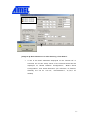
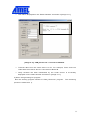
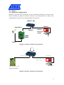
)#&&-* X G YG Y G ZG Z G [Image 5-2] Design Step 5.1 Step 1 5.1.1 Network configuration [Image 5-3] shows that information can be transferred between the computer and serial device through the network with two @WEB SEG32 modules with no changes made to the existing serial communication system. lGoG lGo G zGG zG G lG l G g~liG zlnZYG zlnZY G g~liG zlnZYG zlnZY zG z G G [Image 5-3] Step 1 Network Configuration •= Connect the computer and @WEB SEG32 Evaluation board (“Board A”) by using RS-232 as shown in [Image 5-3]. •= Connect the serial device to a @W EB SEG32 Evaluation board (“Board B”) also using RS-232. •= Connect Board A and Board B to the hub. •= Connect the computer to the hub (required for environment setting of the @W EB SEG32 module) •= Set the switch to ON position after connecting power to each Board A and Board B. 5.1.2 @WEB SEG32 Environment Setup • Run “IGM_Cfgtool.exe”. [Image 5-4] “IGM_Cfgtool.exe” Initialization Window •= Click “Search” button. •= If two boards are properly connected to the network, “/#1 )” message and MAC address of Board A and Board B will be displayed as shown in [Image 5-5]. [Image 5-5] Board Results List after Running “Find Board” •= If one of the MAC addresses displayed on the “Board List” is selected, the current setup values of the selected board will be displayed on “Board Network Configuration”, ”Board Serial Configuration”, and “Mode Selection” (for reference, IP, Subnet, Gateway are set as “0.0.0.0”, “255.255.255.0”, “0,0,0,0” as default) [Image 5-6] Initial Setup Value of Located Boards •= To modify the setup values, press “Set up” after designating the IP address, etc., then the inserted values will be setup at the board and message box showing “Setting complete” will be displayed. [Example] Setting Board A and Board B (1) Setting Board A 1) Network Configuration Insert following values in the board network configuration IP Address 211.171.137.10 Subnet 255.255.255.0 Gateway 211.171.137.1 2) Serial Configuration Select following values in the board serial configuration (These values is example, so you should adjust Speed and Parity according to your serial devices). Speed 57600 Parity None Data bit 8 Stop bit 1 Flow None 3) #$1.# Select server mode, that is, not check ‘. !’% and set listen port at 3000 and Click “Set up” button. [Image 5-7] Board A Sample Setup (2) Setting Board B 1) Network Configuration Insert following values in the board network configuration IP Address 211.171.137.11 Subnet 255.255.255.0 Gateway 211.171.137.1 2) Serial Configuration Select following values in the board serial configuration. (These values is example, so you should adjust Speed and Parity according to your serial devices). Speed 57600 Parity None Data bit 8 Stop bit 1 Flow None 3) #$1.# Select client mode, that is, check ‘. !’% and insert Board A’s IP address and port number. Click “Set up” button. } [Image 5-8] Board B Sample Setup •= Conduct ping test on the computer to see whether Board A and Board B are properly connected to the network. [Image 5-9] Ping test 5.1.3 Confirming Operation 1) W hen using “IGM_PCutil.exe” •= Disconnect the UTP cable for @W EB SEG32 environment setup. •= Run “IGM_PCutil.exe” program on the computer. Program window will be displayed as shown as [Image 5-10]. •= Select “Serial” of the “Input Selection” menu as shown in [Image 5-10]. •= Set the values of the tabs of the “Serial Part” menu identical to the serial setup value as set by “IGM_Cfgtool.exe” and click “Open” button. [Image 5-10]”IGM_PCutil.exe” Program Window • Press reset button of each Board A and Board B and wait for about 2~3 seconds (time required for initialization) •= Text will be displayed on the “Status W indow” as shown in [Image 5-11]. [Image 5-11] “IGM_PCutil.exe” Connection Window •= Transmit data from the serial device to PC. For example, Scan some bar codes with the scanner which is connected to Board B. •= Verify whether the data transmitted by the serial device is accurately displayed ion the status window as shown in [Image 5-11]. 2) W hen using existing PC program Run the existing program instead of “IGM_PCutil.exe” program. The remaining process is identical to 1). 5.2 Step 2 5.2.1 Network Configuration [Image 5-12] shows the change of existing PC application program to Ethernet communication program after removal of Board A from Step 1. lGoG lGo G l zGG zG G wjG wj G g~liG zlnZY G g~liG zG z G G zlnZY G zG zG G [Image 5-12] Step 1 Network Configuration lG lG G oG oG lG l G zGG zGG lG l G tG t G hG h G G g~liG z lnZYG lnZY G wjG wj G zG z G G [Image 5-13] Step 2 Network Configuration •= Remove Board A from the computer as shown in [Image 5-13]. •= Connect the serial device to Board B by using RS-232. •= Connect Board B to the hub. •= Connect the computer to the hub. •= Connect power to Board B. 5.2.2 @WEB SEG32 Environment Setup The setup is identical to Section 5.1.2 with the exception that only one @WEB SEG32 Evaluation board is comprised in this process (refer to Section 5.1.2) 5.2.3 Confirming Operation 1) W hen using “IGM_PCutil.exe” •= Run the “IGM_PCutil.exe” program on the computer. The program window will be displayed as shown in [Image 5-14]. •= Select “Ethernet” of the “Input Selection” menu as shown in [Image 5-14]. [Image 5-14]”IGM_Pcutil.exe” Program Window •= As shown in [Image 5-15].Set the port number identical to Board A (server) in the server mode and click “Listen” button. •= However, if the @W EB SEG32 connected to the computer was setup in Client Mode during Step 1, then it also needs to be operated in Client Mode. Insert server IP address and port number in the client mode and click “Open” button. [Image 5-15]”Network Part” Setup Window •= Press reset button of Board B and wait for about 2~3 seconds (time required for initialization). Text will be displayed on the “Status W indow” as shown in [Image 5-16]. • [Image 5-16]”IGM_PCutil.exe” Connection Window • Send data from the serial device. • erify whether data sent by the serial device is accurately displayed in the Status W indow as shown in [Image 5-16]. 2) W hen using existing PC program You can test by using “Serial IP” program, which enables Ethernet communication for serial device. 5.3 Step 3 5.3.1 Network Configuration [Image 5-18] shows that information can be transferred between the computer and device ultimately through the Ethernet network by removing Board B in Step 2 and embedding the module on the existing RS232 serial device. lG l G G oG o G lG l G zGG zG G lG l G tG tG hG h G G g~liG wjG wj G zlnZYG zlnZYG zG z G G [Image 5-17] Step 2 Network Configuration Ethernet Ethernet Modified application PC New serial device with @WEB SEG32Module [Image 5-18] Step 3 Network Configuration •= Remove Board B from the serial device connection and embed it on-board to the serial device as shown in [Image 5-18]. •= Connect computer to the hub. •= Connect the new serial device with Board B to the hub. 5.3.2 Confirming Operation The process is identical to Section 5.2.3 with the exception that @WEB SEG32 Evaluation board is installed onto the serial device (refer to Section 5.2.2). The purpose of this step is to describe a new product integrating the serial device and @W EB SEG32 Module, and the executing method is identical to Section 5.2.2. 6 Auxiliary Functions(Firmware Uploading) 6.1 When using “IGM_Cfgtool.exe” program •= Run IGM_Cfgtool.exe after completing board connection. [Image 6-1] “IGM_Cfgtool.exe” Initialization Window •= Click “Find Board” button. •= If the board is properly connected to the network, “Searching completed” message and MAC address will be displayed on the “Board List” as shown in [Image 6-2]. [Image 6-2] Board Search Window •= Select board for upload and click “Upload” button. [Image 6-3] Upload Selection Window •= When the window as shown in [Image 6-4] is displayed, select file for upload and click “Open” button (files must be converted to Hex or bin format before uploading). [Image 6-4] Firmware Selection for Upload •= A dialogue box with “Firmware uploading” will be displayed as shown in [Image 6-5]. Press “Start” button to start uploading the firmware file to flash memory of @W EB SEG32 module. [Image 6-5] Firmware Uploading • When uploading is complete, a message box with “Uploading Success” will be displayed as shown in [Image 6-6]. [Image 6-6] Uploading Complete 6.2 When doing serial upload •= Connect @Web SEG32 Evaluation board serial port and computer serial port by using the serial cable. •= Run terminal emulator such as the hyper terminal and switch on the power. •= When starting, press ‘c’ on the keyboard to start the firmware upgrade mode. Firmware Upgrade Mode is accessible only during the 2-second initialization process, therefore ‘c’ needs to be pressed immediately after initialization otherwise it will be changed automatically to the existing firmware mode. •= •= Insert file size (bin file size) and press enter key. After selecting text file send, select bin file for transmission to transmit the file, update the firmware and complete the firmware update, then a new firmware will be running. [Image 6-7] Hyper Terminal Window