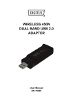
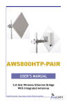
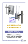
1
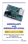
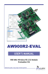
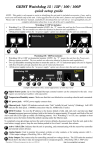
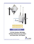
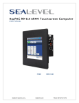
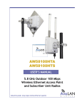
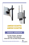
AW5810HTA
AW5810HTS
AW5810HTP-PAIR
USER’S MANUAL
5.8 GHz Outdoor 10 Mbps
Wireless Ethernet Radios
Industrial-grade, long-range wireless Ethernet systems
AvaLAN
W
I
R
E
L
E
S
S
AW5810HTA,HTS,HTP-PAIR
User’s Manual
Thank you for your purchase of a member of the 5.8 GHz Outdoor 10 Mbps family of
wireless Ethernet radios. There are three products in this family:
The AW5810HTS serves as a Subscriber Unit or client in point-to-multipoint wireless
networks and has a 23 dBi flat panel directional antenna. This product includes:
• (1) AW5810HTS Radio
• (1) Heavy Duty Pole-Mount Bracket
• (1) AW-POE18i Power over Ethernet Injector with integrated power supply
The AW5810HTA serves as an Access Point in point-to-multipoint wireless networks
and has a 9 dBi omnidirectional antenna. Each AW5810HTA Access Point can support
multiple AW5810HTS Subscriber Units. This product includes:
• (1) AW5810HTA Radio
• (1) Heavy Duty Pole-Mount Bracket
• (1) AW-POE18i Power over Ethernet Injector with integrated power supply
The AW5810HTP-PAIR is a pre-configured point-to-point Bridge consisting of two
radios with 23 dBi flat panel directional antennas. Note that this product is not
simply two AW5810HTS units but consists of a special higher transmit power
master/client matched pair.
The AW5810HTP-PAIR includes:
• (1) AW5810HTP-AP High Power Access Point Radio
• (1) AW5810HTP-SU High Power Subscriber Unit Radio
• (2) Heavy Duty Pole-mount Brackets
• (2) AW-POE18i Power Over Ethernet Injectors with Integrated Power Supplies
If you have any questions when configuring your AvaLAN system, the best place to
get answers is to visit www.avalanwireless.com. You will also find the latest updates
there.
If more assistance is needed, send email to [email protected].
To speak to a live technician, please call technical support at the number below
during normal business hours.
© 2011 by AvaLAN Wireless Systems Inc. All rights reserved.
Revision 09.05.2011
125A Castle Drive
Madison, AL 35758
Sales: (866) 533-6216
Technical Support: (650) 384-0000
Customer Service: (650) 641-3011
Fax: (650) 249-3591
Technical Support (650) 384-0000
PAGE 2
www.avalanwireless.com
User’s Manual
AW5810HTA,HTS,HTP-PAIR
Operational summary
The AW5810HT family of products allows the user to create long-range, point-to-point
or point-to-multipoint wireless Ethernet connections. These radios conform to IEEE
802.11a. In order to provide the greatest range, minimum latency and most robust
data communication possible, they are configured for an RF channel bandwidth of 10
MHz. The number of available RF channels and their frequencies are set by regulatory
bodies depending upon the country. The physical packaging and RF output power settings for these products are appropriate for the “Outdoor” band from 5740 to 5830
MHz. It is your responsibility to make sure these radios are configured to conform to
legal requirements where they are deployed. (Please note that other AvaLAN 5.8 GHz
radios can exist on the same LAN but cannot be used to form wireless links with the
AW5810HT family because the RF parameters are different.)
In point-to-multipoint configurations, a single AW5810HTA acts as the master or access point (AP). Several AW5810HTS clients or subscriber units (SU) may be pointed
toward the AW5810HTA. All the radios in the network must share common SSIDs and
encryption keys. The AP is configured for a particular RF channel and the SUs locate
and switch to this same frequency. Each radio encrypts Ethernet data received from
its LAN port and transmits it wirelessly to the others. The AP runs a WDS (Wireless
Distribution Service) process for each SU to manage the traffic flow.
The point-to-point AW5810HTP-PAIR Bridge consists of a single AP and single SU. When
configured and mounted with antennas aimed at each other, they operate as a bridge
providing a wireless virtual LAN cable.
For either type of network to function, these five configuration elements must be set
for each radio:
1.IP address and subnet mask
2.User password
3.SSID (Service Set Identifier)
4.Encryption pass phrase
5.Frequency Channel
Each unit is equipped with a built-in web browser interface that may be used to
change these configuration parameters and check the link status. Each radio’s IP address must be known and your computer and the radio must have compatible subnet
masks in order to browse to it. The IP address may be changed through the browser
interface, but this creates a “chicken and egg” problem. If the default IP addresses
set by the factory are not suitable, you may need to temporarily connect them to
a computer that can browse to the units for reconfiguration. (Note that the default
configurations should work out of the box but provide very poor security because the
passwords are publicly available. Of course, if multiple AW5810HTS units are to be
connected, all but one of their IP addresses will have to be changed to be unique.)
Technical Support (650) 384-0000
PAGE 3
www.avalanwireless.com
AW5810HTA,HTS,HTP-PAIR
User’s Manual
Physical Setup
1. Before mounting the units in their final locations, you may want to perform the
digital setup procedure described in the next section.
2. Mount each unit securely using the mounting brackets provided or other means
as necessary. Maximize lightning resistance by providing a strong DC ground connection to the metal housing.
3. The units may be mounted with horizontal or vertical polarization and it is important that the antennas be pointed toward one another and be oriented with the
same polarization. Because the 3 dB beamwidth of the flat panel antennas is just
10°, careful aiming is very important − especially over long distances.
4. Power is provided to the units by means of their Ethernet cables, allowing the
power supplies to be located at convenient locations. The included power-overEthernet injectors (POE) provide the means for adding DC power to unused wires in
the cable. Decide where to place each POE based on proximity to AC power at some
point along the desired path of the Ethernet cable. Plug the AW-POE18i’s power cord
into an appropriate outlet. Connect an Ethernet cable between your network and
the “DATA IN” port on the POE. Connect a second cable from the “P + DATA OUT”
port on the POE and the AvaLAN radio. Each radio is provided with a cable clamping
device that allows an RJ45 plug on the cable to pass through and can be tightened
down around the cable to provide a weatherproof seal.
Digital Setup
Connecting to the radio
1. Digital configuration is done by means of the radio’s built in browser interface.
The unit should be powered on and connected at least temporarily to a network
containing a computer that can run a conventional web browser.
2. The default IP address of the Access Point or master unit is 192.168.88.12. The
default IP address of the Subscriber Unit or client is 192.168.88.10. You will find this
default IP address of each unit on its product label. If these are acceptable in your
network configuration, they needn’t be changed. If not, you will need to connect
each unit temporarily to a computer whose wired LAN port has an IP address of
192.168.88.xxx (with xxx not 12 or 10). In other words, the computer that will run
the web browser must connect to the same subnet as each radio being configured.
3. It is extremely important that you keep track of the IP address and login information for each radio. If you lose this information, you will need to contact AvaLAN
Technical Support for assistance.
Technical Support (650) 384-0000
PAGE 4
www.avalanwireless.com
User’s Manual
AW5810HTA,HTS,HTP-PAIR
4. Using your web browser, connect to the IP address of the radio. If you are
successful, you should see this login screen:
click
The factory default login name is “admin” and the password is “password”.
If access security is a concern, the password should be changed.
5. If your login is successful, you should see a status window similar to this:
The web server software built in to your AvaLAN radio is shared with other product
configurations. There are some features of the interface that are not used and even
a few that can cause serious difficulties. An example is the “Advance Options”
dropdown list. Please do not experiment!
Technical Support (650) 384-0000
PAGE 5
www.avalanwireless.com
AW5810HTA,HTS,HTP-PAIR
User’s Manual
6. Main Menu: The menu at the left side of the browser
window chooses among major sections of the interface:
• Wireless - This page is where most of the status
checking and confguration is done.
• IP Addressing > Set IP/subnet - This page is where
the IP address and subnet mask may be changed.
• System > Password - This page is where the user
login password may be changed.
• System > Reboot - Performs a complete restart of
the radio. If you changed the IP address or password, make sure you know what they are before
doing this!
7. Top buttons: Along the top of the window are a set of
buttons:
• Undo - Removes the most recent change to the configuration
• Redo - Reapplies the last change
• Hide Passwords - Toggles display of password boxes from actual text to
“●●●●●●●●” (Note this function does not work when changing the User
Password, but does when setting the encryption pass phrase.
• Safe Mode - If active (dark grey), abnormal termination of your session (e.g.
power loss) will cause any configuration changes to be cancelled.
• Log out - Terminates your session and returns you to the login screen
8. Version: In the upper right is a label that tells you the version of the web interface and also whether the radio is an AP (Access Point) or SU (Subscriber Unit). If
the version number is not the same as shown below, you might want to visit www.
avalanwireless.com to see if a newer version of this manual exists before proceeding further.
9. Important Note: Use only the navigation tools provided within the web interface.
Do not use your browser’s back button or page reload. Doing so will likely force you
to log in again.
Technical Support (650) 384-0000
PAGE 6
www.avalanwireless.com
User’s Manual
AW5810HTA,HTS,HTP-PAIR
Changing The Configuration - Step by Step
Again please remember that if you change the IP Address or User Password and
forget their new values, you have locked yourself out of the browser interface.
Recovery can be a time-consuming process and will require the help of AvaLAN
Technical Support. If you are changing parameters over the RF link (we do not recommend this), be sure to make the remote changes first because the link will be
broken if the SSIDs or Security Pass Phrases do not agree.
1. Setting the IP Address and subnet mask:
• On the Main Menu at the left side of the browser window, click “IP
Addressing”, then click “Set IP/subnet.”
• The current IP Address is shown in the table. Click it to bring up the page that
allows you to change it.
• Enter a new IP Address and subnet, following the instructions on the page for
the subnet notation to be used. Make sure you will be able to browse to the
new address with your computer. Also, make sure that the new IP address is
unique on your LAN subnet.
• Click “Apply.” Nothing appears to happen, but you have been disconnected
and will need to browse to the new IP Address to login again.
2. Setting the User Password:
• On the Main Menu at the left side of the browser window, click “System”,
then click “Password.”
• Enter the old password and the new password twice in the boxes indicated.
• Click the “Change” button.
• Log out and log back in to test.
3. Setting the SSID:
• On the Main Menu at the left side of the browser window, click “Wireless.”
Then click anywhere in the “Wireless_Radio” row to bring up the “Interface
<Wireless_Radio>” page.
• The third line down in the content table shows the current SSID and provides
a text box to change it. Change the SSID to a new value of your choice and
click “OK” or “Apply.”
• You will need to browse to the radio’s IP Address and login again after the
change.
4. Setting the Encryption Pass Phrase:
• On the Main Menu at the left side of the browser window, click “Wireless.”
Then click the “Security Profiles” tab to bring show the two pre-defined
Technical Support (650) 384-0000
PAGE 7
www.avalanwireless.com
AW5810HTA,HTS,HTP-PAIR
User’s Manual
profiles available.
• Click in the “WPA2-AES-PSK2” row to bring up a page that shows the PreShared Key and provides a text box to change it. You may want to toggle the
“Hide Passwords” button at the top of the browser window to make the Key
text visible.
• Enter the new Pre-Shared Key you have chosen and click “OK” or “Apply.”
• If you would rather eliminate encryption and use the “default” profile, you
can change the choice of profile on the “Interface <Wireless_Radio>” page
described earlier under setting the SSID. The Security Profile dropdown list
may be found right under the SSID box on that page.
5. Setting the Frequency Channel:
• On the Main Menu at the left side of the browser window, click “Wireless.”
Then click anywhere in the “Wireless_Radio” row to bring up the “Interface
<Wireless_Radio>” page.
• The second row in the content table shows the current Radio Frequency and
provides a dropdown list of alternatives. There are more choices available
in the dropdown list than are legal or appropriate for this set of products.
Please choose from among the 802.11a Upper Band frequencies between
5740 MHz and 5830 MHz. These frequencies are spaced every 5 MHz, but the
channel bandwidth is 10 MHz. To avoid overlap, make sure that you choose
channels for AP units operating in proximity that are at least 10 MHz apart.
See the table on the last page of this manual.
• Change to the Frequency desired and click “OK” or “Apply.”
• Note that the important Frequency Channel setting is made on the AP. You
may also set the Frequency Channel on SUs, but if they don’t find an AP on
that channel, they will search and automatically switch to the Frequency
Channel of the AP with a matching SSID.
Technical Support (650) 384-0000
PAGE 8
www.avalanwireless.com
User’s Manual
AW5810HTA,HTS,HTP-PAIR
Viewing Status Information
After configuring your AvaLAN radios and establishing links among them, you can
use the browser interface to view status and troubleshooting Information. Choose
“Wireless” from the Main Menu at the left side of the window. The “Wireless Tables”
page leads to all of the useful status information.
This page has three tabs, Interfaces, Associations and Security Profiles. Please ignore the “Advanced Options” dropdown as it has no purpose for these products.
1. Interfaces Tab: This provides a list of the interface processes running in this radio. If it is a SU, there will be only one, “Wireless_Radio.” If it is an AP, there will
also be a WDS process running for each SU that is connected.
Status information that is visible on this page includes the current transmit and
receive bits per second, the number of packets sent and received since last reboot
and the packet drops and errors encountered. For the “Wireless_Radio” process,
the table includes the radio’s RF frequency and SSID.
2. Associations Tab:
This provides a list of radios that are connected, showing their MAC addresses, how
long the connection has been up, seconds since last activity, Transmit and receive
signal strength in dBm and the transmit and receive data rate in use.
Technical Support (650) 384-0000
PAGE 9
www.avalanwireless.com
AW5810HTA,HTS,HTP-PAIR
User’s Manual
3. Security Profiles Tab:
There are two security profiles available. “WPA2-AES-PSK2” is 256-bit encryption
using a pre-shared key. “default” is open and unencrypted. Clicking on the “WPA2AES-PSK2” line brings up a screen where the pre-shared key may be viewed and
changed.
4. Wireless_Radio Status Page: Back on the Interfaces tab, clicking on the “WirelessRadio” line in the table brings up a page that shows more information about the
radio’s status and configuration.
Technical Support (650) 384-0000
PAGE 10
www.avalanwireless.com
User’s Manual
AW5810HTA,HTS,HTP-PAIR
This page displays the current RF frequency, the SSID, the Security Profile in use,
current transmission rates, amount of data sent and received since last reboot,
drops and errors. Also shown are graphs of megabits per second and packets per
second during the last three minutes or so. The graphs are well labeled and autoscale to fit the data. After viewing the status, you may leave the page by clicking
“Cancel” or by using the Main Menu. (If you click “OK” or “Apply”, the process will
restart and briefly interrupt the data flow.
If you are browsing to the AP in a point-to-multipoint system with several SUs, clicking on one of the WDS lines on the Interfaces Tab brings up a similar screen showing
only the traffic with that specific SU.
5. AP Client Status Page: From the Associations tab, clicking on one of the lines in
the table brings up a page showing the status of the remote end of the wireless link.
Several pieces of information related to the radio link quality are shown here.
• Tx/Rx Signal Strength in dBm as measured by the radio’s receiver
• Signal to Noise ratio
• CCQ (Client Connection Quality) shows the average percentage of theoretical
connection bandwith achieved with the current level of retries.
• P Throughput is the currently achieved peak data rate.
Technical Support (650) 384-0000
PAGE 11
www.avalanwireless.com
AW5810HTA,HTS,HTP-PAIR
User’s Manual
Frequency Channels
Frequency
Band
Frequency
MHz
AvaLAN
non-overlapping
preferred
802.11a
Upper Band
(FCC specifies
for Outdoor use)
5740
5745
5750
5755
5760
5765
5770
5775
5780
5785
5790
5795
5800
5805
5810
5815
5820
5825
5830
OK
ISM Band
OK
OK
OK
OK
OK
OK
OK - Default
OK
OK
Regulatory Domain
FCC and
Rest of World
Americas
OK
OK
OK
OK
OK
OK
OK
OK
OK
OK
OK
OK
OK
OK
OK
OK
OK
OK
OK
OK
OK
OK
OK
OK
Limited Warranty
This product is warranted to the original purchaser for normal use for a period of 360 days
from the date of purchase. If a defect covered under this warranty occurs, AvaLAN will repair
or replace the defective part, at its option, at no cost. This warranty does not cover defects
resulting from misuse or modification of the product.
Technical Support (650) 384-0000
PAGE 12
www.avalanwireless.com