1
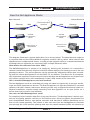
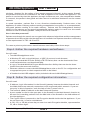
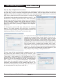
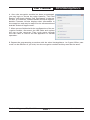
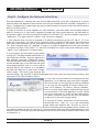
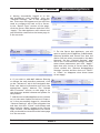
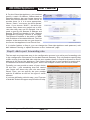
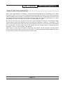
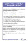
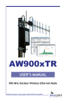
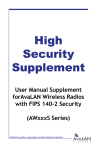
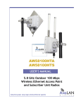
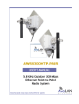
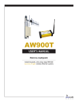
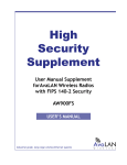
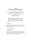
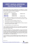
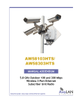
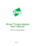
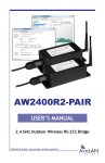
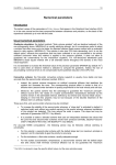
AW-HSNetAppliance
User’s Manual
FIPS 140-2
High Security
Network Appliance
Industrial-grade, long-range wireless Ethernet systems
AvaLAN
W
I
R
E
L
E
S
S
AW-HSNetAppliance
User’s Manual
Thank you for your purchase of these AvaLAN AW-HSNetAppliance FIPS 140-2 High Security
Network Appliances.
The AW-HSNetAppliance is used to create a secure Ethernet communications tunnel through
untrusted data transport systems. The security of the tunnel is provided by the NetAppliance’s
AES-256, FIPS140-2 Level 2 validated, data encryption system. The NetAppliance is typically
deployed as a cryptographically matched pair, each at a trusted network location, to create a
network-to-network VPN tunnel over the Internet or via wireless communications equipment.
Each AW-HSNetAppliance includes:
• (1) High Security Network Appliance
• (1) 120 VAC to 6 VDC Power Supply
• (1) Standard to Mini-USB Adapter Cable
Table of Contents:
How the Net Appliance Works . . . . . . . . . . . . . . . . . . . . . . . . . . .
3
Step A. Gather Required Hardware and Software . . . . . . . . . . . . . . . . . .
4
Step B. Gather the Required Configuration Information . . . . . . . . . . . . . . .
4
Step C. Configure the Encryption Modules . . . . . . . . . . . . . . . . . . . . . .
5
Step D. Configure the Network Interfaces . . . . . . . . . . . . . . . . . . . . .
8
Step E. Add a Port Forwarding Rule . . . . . . . . . . . . . . . . . . . . . . . . .
10
Step F. Test the Connection . . . . . . . . . . . . . . . . . . . . . . . . . . . . . .
11
Required Information
12
Form . . . . . . . . . . . . . . . . . . . . . . . . . . . . . .
If you have any questions when configuring your AvaLAN system, the best place to get answers
is to visit www.avalanwireless.com. You will also find the latest updates there. If more assistance is needed, send email to [email protected].
To speak to a live technician, please call technical support at the number below during normal
business hours.
Limited Warranty:
This product is warranted to the original purchaser for normal use for a period of 360 days
from the date of purchase. If a defect covered under this warranty occurs, AvaLAN will repair
or replace the defective part, at its option, at no cost. This warranty does not cover defects
resulting from misuse or modification of the product.
© 2012 by AvaLAN Wireless Systems Inc. All rights reserved.
Revision 06.26.2012
125A Castle Drive
Madison, AL 35758
Sales: (866) 533-6216
Technical Support: (650) 384-0000
Customer Service: (650) 641-3011
Fax: (650) 249-3591
Technical Support (650) 384-0000
PAGE 2
www.avalanwireless.com
User’s Manual
AW-HSNetAppliance
How the Net Appliance Works
Linked Network
Main Network
Gateway
WAN
Unsecured Public
Network
AvaLAN
Net Appliance
Server
Gateway
WAN
AvaLAN
Net Appliance
Client
Data Source or
Destination
Data Source or
Destination
This diagram illustrates a typical application for a secure tunnel. The Main Network might be
a corporate LAN and the Linked Network might be a public LAN in a hotel. When the two Net
Appliances are configured and linked, a virtual private network (VPN) is created that behaves
as though the two networks are connected with a simple Ethernet cable.
What makes this different from other VPNs?
The AW-HSNetAppliance is unique in its simplicity, allowing the formation of a network-tonetwork connection that only requires a fixed IP address and port forwarding at one of the two
gateway locations. The second gateway can be dynamically addressed without port forwarding and the remote Net Appliance can use DHCP for its address. This allows for an exceptionally simple user experience at the second location because the Net Appliance can be placed on
any remote network and it will immediately create a VPN tunnel to the other side.
How is the AW-HSNetAppliance used and installed?
Two Net Appliances work as a matched pair using the same encryption key to encrypt and decrypt the traffic between the devices. The first Net Appliance is typically installed on a trusted
network with MAC address restrictions allowing access only to approved network resources.
Physical installation requires simply attaching each Net Appliance to an open socket on a
switch that is part of each local network.
How does the AW-HSNetAppliance work?
For simplicity let us consider data flow in just one direction. The Net Appliance’s tunnel operates by encrypting packets received on its Ethernet port. Once encrypted, the packets are
then encapsulated within a new packet structure that has the IP address destination set to
that of the remote gateway. The packet is then sent out from the NetAppliance’s Ethernet
port through the local network gateway and onto the unsafe network (often the Internet or
Technical Support (650) 384-0000
PAGE 3
www.avalanwireless.com
AW-HSNetAppliance
User’s Manual
wireless), destined for the safety of the remote gateway’s firewall. At the remote firewall,
the packet arrives and is forwarded to the LAN IP address of the remote Net Appliance. The
packet is received by that Net Appliance through its Ethernet port, the encapsulation header
is removed, the packet is decrypted and then sent to its ultimate destination on the remote
network.
In actual operation, packets flow in two directions simultaneously. Packets enter a Net
Appliance as either ordinary packets needing encapsulation/encryption or as encapsulated/
encrypted packets needing to be made ordinary. Packets exit the NetAppliance destined
either for the gateway as encrypted/encapsulated packets ready for travel over the unsafe
network or exit as ordinary packets ready for the local network.
How is the data protected?
Packets sent through the tunnel are encrypted with advanced algorithms and the management
of passwords and keys within the Net Appliance is handled via a separate interface conforming
to the requirements of FIPS 140-2 Level 2.
To create a point-to-point secure tunnel between two LANs, follow these steps:
Step A. Gather the required hardware and software.
You will need:
• Two AW-HSNetAppliance units.
• A Windows PC with a wired LAN port, a USB 2.0 port and a web browser.
• A copy of the AvaLAN IP Finder Utility (xTR/iTR series) that can be downloaded from
www.avalanwireless.com/downloads.php.
• A copy of the AvaLAN AW140 Crypto Module Interface Utility that can also be downloaded from the same web location.
• Ethernet cables to connect the AW-HSNetAppliance units to the PC for configuration and
to appropriate ports on their respective LANs to be linked.
• A Standard to Mini USB adapter cable (included with each AW-HSNetAppliance).
Step B. Gather the required configuration information
You will need:
• IP Address, login information for the firewall/gateway between the Main Network and
the WAN (wide area network) connection to the unsecured public network. If you are
not privy to this information, seek the help of the IT person who is.
• The external (WAN) IP address at the Main Network location.
• A port number to use for the open port in the firewall for the Main Network location to
be used for forwarding packets from the WAN side of the firewall to the LAN address of
the Net Appliance.
• The Crypto Officer’s password to the Encryption Module inside the Net Appliance. If you
do not know this, it can be reinitialized.
• A 128, 192, or 256 bit private key to enter into each Encryption Module, represented as
32, 48 or 64 hex digits.
Technical Support (650) 384-0000
PAGE 4
www.avalanwireless.com
User’s Manual
AW-HSNetAppliance
• The login information to the AW-NetAppliance web interface. This is a default of “ad-
min” and “password.” If it has been changed and you don’t know what it is, you may
need to do a complete reinitialize.
• A static IP address, netmask and gateway address for the Net Appliance at the Main
Network location. (Seek the help of the IT person for the Main Network if you do not
have direct control over this.)
• MAC addresses of any devices that are allowed to use the Net Appliance’s tunnel (all
devices are allowed by default, but you can limit this to a list of up to 24 specific
devices at each end.)
We recommend writing down a list of these items before proceeding further. You will need
the answers to all of the above to complete the configuration of your secure tunnel. For your
convenience, use the form provided in the back of this manual.
Step C. Configure the Encryption Modules
To program the encryption module within the AW-HSNetAppliance, a PC must be connected to
the USB port on the end of the case:
The PC must have two critical pieces of software installed:
1.
A driver that provides a virtual COM port through the USB connection. Such a driver is
already included with Windows XP, Vista or 7 and should automatically be located and
loaded when the USB connection is first made.
2.
The AW140 Crypto Module Interface utility that can be downloaded from our website,
www.avalanwireless.com. Look for it on the Downloads page under the Support tab. The
file is a zip archive containing an installer for the utility. Unzip and run it to install the
utility on your PC.
If you prefer to use a computer with a non-Windows operating system, it is also possible to
program the module with a virtual COM port driver and a generic terminal emulator. Contact
AvaLAN Technical Support for help with this feature.
The person having access to the programming interface is referred to by the FIPS 140-2
Standard as the Crypto Officer. As the Crypto Officer, part of the responsibility for data security rests with your choice of a strong login password and encryption key. Make sure you do not
lose the login passwords and encryption key because they cannot be retrieved from the Net
Appliances in any fashion.
Technical Support (650) 384-0000
PAGE 5
www.avalanwireless.com
AW-HSNetAppliance
User’s Manual
Step by Step Configuration Procedure:
1. Turn off the power to the Net Appliance by unplugging its DC power cable and connect
the USB port to your computer using the USB mini B cable. Then re-apply power to the Net
Appliance. The unit’s encryption module will enter its programming mode only if a powered
USB cable is attached and the main power is cycled off and then on.
2. Run the Crypto Module Interface utility on your PC. You
should see a startup window like this, with everything
greyed out except the Connect button and a dropdown
list of COM ports. Usually there will be just one. If there
are more, repeat Step 1 to determine which COM port
applies to this radio by seeing it disappear and reappear
in the list.
3. Choose the correct COM port and press the Connect
button. The utility window will then show a successful
connection by activating the Login and Reset choices and
displaying “Module Connected” in the status box.
4. If you know the Crypto Officer password and want to
change the encryption key, choose Login. if you are initializing the module for the first time or wish to reset
both the password and key, choose Reset. After a warning popup, you will be able to enter a new Crypto Officer
password. This must be between 8 and 32 characters and
may include letters, numbers and symbols and is casedependent. If you forget the password, there is no way to
retrieve it. You will need to reset the module and begin
again. If you know the password and have logged in, you
may change it by clicking “Change Password.”
5. Next, you will be provided with a popup to enter the
encryption key and method (128, 192 or 256-bit). (You
will be forced here if you are resetting, or can choose
“Input Key” after logging in. The encryption key is a
hexadecimal number, 32 digits for 128-bit encryption, 48
digits for 192-bit and 64 digits for 256-bit. Enter the digits
as 0 - 9 and a - f or A - F (case independent). If you enter
fewer than the specified number of digits (not recommended), the remainder will be padded with zeros. (To
avoid errors and preserve your sanity, you will likely want
to cut and paste this key from a text file.)
Technical Support (650) 384-0000
PAGE 6
www.avalanwireless.com
User’s Manual
AW-HSNetAppliance
6. Once the encryption module has been programmed,
you may login to access the other features. “Self Test
Results” will simply display “Self Test Passed” in the status box. If it does not, contact AvaLAN Technical Support.
Module Firmware Version displays that information in
the status box and may be useful to the aforementioned
AvaLAN Technical Support staff.
7. When you are finished with the configuration of the encryption module, disconnect the USB cable and replace
the cap on the connector. Then cycle power through
the LAN cable to restore the Net Appliance to normal
operation.
8. Repeat the programming procedure with the other Net Appliance. its Crypto Officer password can be different if you wish, but the encryption method and key must be the same.
Technical Support (650) 384-0000
PAGE 7
www.avalanwireless.com
AW-HSNetAppliance
User’s Manual
Step D. Configure the Network Interfaces
One Net Appliance, normally the one on the Main Network, must be configured as a Server
and the other Net Appliance that will be used on the Linked Network must be configured as a
Client. Configuration is performed by using a web browser to interact with the web interface
built in to the product.
In order to browse to a Net Appliance’s web interface, you must know its IP Address and be
able to connect to it from your computer through the local wired network. As indicated on
the product label, the factory default IP Address is 192.168.17.17 and the default password is
“password.” The login name is “admin” and cannot be changed.
1. Your network may not have a netmask or IP address range that can see 192.168.17.17. So to
make the connection, you will need a computer such as a laptop PC that has a wired LAN port
and whose LAN interface can be changed at least temporarily to 192.168.17.xxx (“xxx” not
17). After changing your PC’s address, connect it to the Net Appliance and use your browser
to connect to http://192.168.17.17. You will be asked for a login name and password: enter
“admin” and “password” for these items.
2. If successful, you will see a screen similar
to this one. The page header shows the current Firmware Version, the Net Appliance’s
MAC Address, the type of Ethernet connection and the time since last reboot. Clicking
on the AvaLAN logo or the URL link will open
www.avalanwireless.com in a new tab or
window. Below the header is a navigation
bar that can take you to two other configuration pages. This home page displays the
current status, the amount of data exchanged since last reset and the activity load on the
encryption CPU. Skip ahead to Step 4.
3. If you are not successful at browsing to the Net
Appliance, its IP address may have been changed.
You can choose to reset the unit to factory defaults
or you can use our AvaLAN IP Finder Utility to locate its IP address. To reset to factory defaults,
there is a small white button visible through a hole
on the bottom of the Net Appliance’s case. While
the unit is powered on, press and hold this button
for about 5 seconds (you will see the LED display
on the top of the case change state).
To use the IP Finder, download it from www.avalanwireless.com. Look for it on the Downloads
page under the Support tab. The file is a zip archive containing the executable utility. Unzip it to
any desired folder on your PC and run it. Clicking search will show all AvaLAN devices on the
network (there should be just the Net Appliance) and the information shown should allow you
to browse to it.
Technical Support (650) 384-0000
PAGE 8
www.avalanwireless.com
User’s Manual
AW-HSNetAppliance
4. Having successfully logged in to the
Net Appliance’s web interface, click the
“General Settings” tab in the navigation
bar. This screen will appear and you will first
need to configure this unit to be a Server.
In the “Device Type” section of the page,
click the Server radio button and then click
“Apply.” The Net Appliance will reboot and
you should be returned to the home page in
a few seconds.
5. For the Server Net Appliance, you will
need to specify the IP Address, Subnet Mask,
Gateway Address and Tunnel Port that the
device will use when connected to the Main
Network. On the “General Settings” page
and in the “Local Network Settings” section,
enter these parameters and click “Apply.”
Note that your choice of Server rather than
Client caused the “Remote NetAppliance
Settings” section and the choice of “DHCP”
or “Static” to disappear since these items
do not apply.
6. If you wish to add MAC Address filtering
or change the web interface password, click
on the “Advanced” tab in the navigation bar.
Enter the desired information and click the
appropriate “Apply” buttons. The “Upload
New Firmware” section on this page is for
use whenever AvaLAN releases an update for
the product.
7. With the second Net Appliance unit, browse
to it in the same fashion as before in Steps 1
to 3. Once successfully logged in, choose the
“General Settings” tab in the navigation bar
and then click the “Client” radio button and
then click the “Apply” button in the “Device
Type” section. The Net Appliance will reboot
and you should be returned to the home page
in a few seconds.
Technical Support (650) 384-0000
PAGE 9
www.avalanwireless.com
AW-HSNetAppliance
User’s Manual
8. For the Client Net Appliance, you need not
specify a static IP Address, Subnet Mask or
Gateway Address, but can choose instead to
allow the Linked Network’s DHCP Server to
provide them. Or if it is more appropriate,
choose “Static” and enter the three parameters. If you choose “DHCP”, the three parameter entry boxes are grayed out to indicate that they may not be changed. You do
need to specify the Remote IP Address and
Remote Tunnel Port Number in the “Remote
NetAppliance Settings” section of the page.
The Remote IP Address is the public or WANside IP Address of the Main Network. The Port
number is the same as the one you chose for
the Server Net Appliance Local Tunnel Port.
9. In similar fashion to Step 6, you can change the Client Net Appliance web password, add
MAC Address Filtering or update firmware on the “Advanced” page.
Step E. Add a port forwarding rule
The last and very important step in the configuration process is to add a port forwarding rule
in the configuration information for the Main Network Gateway. This rule needs to specify that
traffic arriving from the WAN side with the port number chosen in Step B is directed to the IP
Address of the Server Net Appliance. Each router/firewall has its own method for setting this,
so detailed instructions cannot be given. Here is an example screen from one such router:
Typically you can provide a name of your choice
for the rule — pick something that will remind
your future self about why the rule was established. Then, you can specify the port number
and the IP address as well as the type of traffic
allowed.
If you have difficulty with this step, your IT person
or AvaLAN Technical Support may be able to help.
Technical Support (650) 384-0000
PAGE 10
www.avalanwireless.com
User’s Manual
AW-HSNetAppliance
Step F. Test the connection
When the configuration is complete, connect the Net Appliances to available ports on their
respective LANs, the Server on the Main Network LAN and the Client on the Linked Network
LAN and apply power to them. A computer on the respective LAN can be used to browse to the
Net Appliance there to check on the status. An even easier, though less complete way to check
the status is to view the LEDs on the top of the Net Appliance case.
As soon as the units are connected and active, they attempt to connect. The Statistics page
(home page) of each Net Appliance and its LEDs will indicate a status of “Searching.” The
Server will remain in this state until the Client makes connection, then the status will change
to “Connected.” On the Client side, if the Server does not connect after 2 minutes an error
message, “Server is unreachable” will appear.
When the two units are successfully connected, the tunnel can be tested by sending traffic
from a device on one LAN to a device on the other. The Net Appliance Statistics page will show
incrementing counts of transmitted and received data.
Technical Support (650) 384-0000
PAGE 11
www.avalanwireless.com
AW-HSNetAppliance
User’s Manual
Required Information Form
1. Firewall/gateway for the Main Network:
IP Address: ____.____.____.____
Login Name: __________________________
Tunnel Port #: _________________________
Ext (WAN) IP Address: ____.____.____.____
Password: ____________________________
2. FIPS 140-2 Encryption (set alike in both Net Appliances):
Crypto Officer’s Password: ____________________________
Method:
128 Bit
192 Bit
Encryption Key:
32, 48 or 64 Hex Digits
256 Bit
3. Server Net Appliance:
IP Address: ____.____.____.____
Subnet Mask: ____.____.____.____
Gateway: ____.____.____.____
Login: admin, Password: ________________
MAC Address Filtering:
Enabled
Disabled
____:____:____:____:____:____
____:____:____:____:____:____
____:____:____:____:____:____
____:____:____:____:____:____
____:____:____:____:____:____
____:____:____:____:____:____
____:____:____:____:____:____
____:____:____:____:____:____
____:____:____:____:____:____
____:____:____:____:____:____
____:____:____:____:____:____
____:____:____:____:____:____
____:____:____:____:____:____
____:____:____:____:____:____
____:____:____:____:____:____
____:____:____:____:____:____
____:____:____:____:____:____
____:____:____:____:____:____
____:____:____:____:____:____
____:____:____:____:____:____
____:____:____:____:____:____
____:____:____:____:____:____
____:____:____:____:____:____
____:____:____:____:____:____
4. Client Net Appliance:
Addressing:
DHCP
Static
IP Address: ____.____.____.____
Subnet Mask: ____.____.____.____
Gateway: ____.____.____.____
Login: admin, Password: ________________
MAC Address Filtering:
Enabled
Disabled
____:____:____:____:____:____
____:____:____:____:____:____
____:____:____:____:____:____
____:____:____:____:____:____
____:____:____:____:____:____
____:____:____:____:____:____
____:____:____:____:____:____
____:____:____:____:____:____
____:____:____:____:____:____
____:____:____:____:____:____
____:____:____:____:____:____
____:____:____:____:____:____
____:____:____:____:____:____
____:____:____:____:____:____
____:____:____:____:____:____
____:____:____:____:____:____
____:____:____:____:____:____
____:____:____:____:____:____
____:____:____:____:____:____
____:____:____:____:____:____
____:____:____:____:____:____
____:____:____:____:____:____
____:____:____:____:____:____
____:____:____:____:____:____
Technical Support (650) 384-0000
PAGE 12
www.avalanwireless.com