1
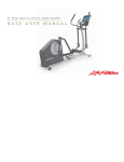
X1 T O T A L - B O D Y E L L I P T I C A L C R O S S - T R A I N E R
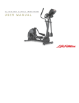
BASE USER MANUAL
CORPORATE HEADQUARTERS
5100 North River Road
Schiller Park, Illinois 60176 • U.S.A.
www.lifefitness.com
INTERNATIONAL OFFICES
LIFE FITNESS ASIA PACIFIC LTD
Room 2610, Miramar Tower
132 Nathan Road
Tsimshatsui, Kowloon
HONG KONG
LIFE FITNESS ATLANTIC BV
LIFE FITNESS BENELUX
Bijdorpplein 25 - 31
2992 LB Barendrecht
THE NETHERLANDS
LIFE FITNESS DO BRAZIL
Av. Dr. Dib Sauaia Neto 1478
Alphaville, Barueri, SP
06465-140
BRAZIL
LIFE FITNESS VERTRIEBS GMBH
Dückegasse 7-9/3/36
1220 Vienna
AUSTRIA
LIFE FITNESS IBERIA
Pol. Ind. Molí dels Frares. c/C, nº 12
08620 Sant Vicenç dels Horts (Barcelona)
SPAIN
LIFE FITNESS UK LTD
Queen Adelaide
Ely, Cambs CB7 4UB
UNITED KINGDOM
LIFE FITNESS EUROPE GMBH
Siemensstrasse 3
85716 Unterschleissheim
GERMANY
LIFE FITNESS JAPAN
Nippon Brunswick Bldg., #8F
5-27-7 Sendagaya
Shibuya-Ku, Tokyo
JAPAN 151-0051
LIFE FITNESS ITALIA S.R.L.
Via Vittorio Veneto, 57/A
39042 Bressanone (Bolzano)
ITALY
LIFE FITNESS LATIN
AMERICA and CARIBBEAN
5100 North River Road
Schiller Park, Illinois 60176
U.S.A.
8117901 Rev A-1
07/06
1
Before using this product, it is essential to read this
ENTIRE operation manual and ALL installation instructions.
This will help in setting up the equipment quickly
and in instructing others on how to use it correctly and safely.
FCC Warning - Possible Radio / Television Interference
NOTE: This equipment has been tested and found to comply with the limits for a Class B digital device, pursuant to part
15 of the FCC rules. These limits are designed to provide reasonable protection against harmful interference in a residential installation. This equipment generates, uses and can radiate radio frequency energy, and if not installed and used
in accordance with the operation manual, may cause harmful interference to radio communications. However, there is no
guarantee that the interference will not occur in a particular installation. If this equipment does cause harmful interference to radio or television reception, which can be determined by turning the equipment off and on, the user is encouraged to try to correct the interference by one or more of the following measures:
Reorient or relocate the receiving antenna.
Increase the separation between the equipment and the receiver.
Connect the equipment into an outlet on a circuit different from that to which the receiver is connected.
Consult the dealer or an experienced radio/TV technician for help.
Class HB (Home): Domestic use. Not suitable for therapeutic purposes.
CAUTION: Any changes or modifications to this equipment could void the product warranty.
Any service, other than cleaning or user maintenance, must be performed by an authorized service representative.
There are no user-serviceable parts.
2
TABLE
OF
CONTENTS
1.
Getting Started . . . . . . . . . . . . . . . . . . . . . . . . . . . . . . . . . . . . . . . . . . . . . . . . . . . . . . . . . . . . . . . . . . . . .5
1.1
Important Safety Instructions . . . . . . . . . . . . . . . . . . . . . . . . . . . . . . . . . . . . . . . . . . . . . . . . . . . . . . . . . .5
1.2
Set-up . . . . . . . . . . . . . . . . . . . . . . . . . . . . . . . . . . . . . . . . . . . . . . . . . . . . . . . . . . . . . . . . . . . . . . . . . . .7
Where to Place the Cross-trainer // How to Stabilize the Cross-trainer // Plug In the Cross-trainer
2.
The Reading Rack and Water Bottle Holder . . . . . . . . . . . . . . . . . . . . . . . . . . . . . . . . . . . . . . . . . . . . . . .8
3.
Correct Usage
3.1
Mounting and dismounting the Cross-Trainer . . . . . . . . . . . . . . . . . . . . . . . . . . . . . . . . . . . . . . . . . . . . . .9
3.2
Biomechanical Guidelines . . . . . . . . . . . . . . . . . . . . . . . . . . . . . . . . . . . . . . . . . . . . . . . . . . . . . . . . . . . .9
. . . . . . . . . . . . . . . . . . . . . . . . . . . . . . . . . . . . . . . . . . . . . . . . . . . . . . . . . . . . . . . . . . . .9
General // Forward Motion – Total Body // Reverse Motion – Total Body // Braking Resistance
4
Service and Technical Data . . . . . . . . . . . . . . . . . . . . . . . . . . . . . . . . . . . . . . . . . . . . . . . . . . . . . . . . . . .11
4.1
Preventative Maintenance Tips . . . . . . . . . . . . . . . . . . . . . . . . . . . . . . . . . . . . . . . . . . . . . . . . . . . . . . . .11
4.2
Preventative Maintenance Schedule . . . . . . . . . . . . . . . . . . . . . . . . . . . . . . . . . . . . . . . . . . . . . . . . . . . .12
4.3
How to Obtain Product Service . . . . . . . . . . . . . . . . . . . . . . . . . . . . . . . . . . . . . . . . . . . . . . . . . . . . . . . .13
5
Warranty Information . . . . . . . . . . . . . . . . . . . . . . . . . . . . . . . . . . . . . . . . . . . . . . . . . . . . . . . . . . . . . . . .14
6
Specifications . . . . . . . . . . . . . . . . . . . . . . . . . . . . . . . . . . . . . . . . . . . . . . . . . . . . . . . . . . . . . . . . . . . . .17
© 2006 Life Fitness, a division of Brunswick Corporation. All rights reserved. Life Fitness is a registered trademark of Brunswick
Corporation. Any use of these trademark, without the express written consent of Life Fitness is forbidden.
3
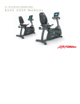
This Operation Manual describes the functions of the following products:
Life Fitness cross-trainer:
X1
See Section 6, titled Specifications page in this manual
for product-specific features.
Statement of Purpose: The cross-trainer is an exercise machine that combines low-impact elliptical pedaling with
push/pull arm motion to provide an efficient, effective total body workout.
Health-related injuries may result from incorrect or excessive use of exercise equipment. The manufacturer
STRONGLY recommends seeing a physician for a complete medical exam before undertaking an exercise
program, particularly if the user has a family history of high blood pressure or heart disease; or is over the
age of 45; or smokes, has high cholesterol, is obese, or has not exercised regularly in the past year. The
manufacturer also recommends consulting a fitness professional on the correct use of this product.
If, at any time while exercising, the user experiences faintness, dizziness, pain, or shortness of breath, he or
she must stop immediately.
4
1
GETTING STARTED
1.1
IMPORTANT SAFETY INSTRUCTIONS
SAFETY WARNING: The safety of the product can be maintained only if it is examined regularly for
damage and wear. See Preventative Maintenance section for details.
•
Before using this product, it is essential to read this ENTIRE operation manual and ALL instructions. The cross-trainer is intended for use solely in the manner described in this manual.
•
Always follow the console instructions for proper operation.
•
Close supervision is necessary when used by or near children, invalids or disabled persons.
•
If the cross-trainer does not function properly after it has been dropped, damaged, or even partially immersed in
water, contact Customer Support Services for assistance.
•
Never insert objects into any opening in the cross-trainer. If an object should drop inside, carefully retrieve it. If the
item is beyond reach, contact Customer Support Services.
•
Never place liquids of any type directly on the unit, except in an accessory tray. Containers with lids are
recommended.
•
Do not use the cross-trainer outdoors, near swimming pools or in areas of high humidity.
•
Keep all loose clothing, shoelaces, and towels away from the cross-trainer pedals.
•
Keep the area around the cross-trainer clear of any obstructions, including walls and furniture.
•
Use caution when mounting or dismounting the cross-trainer. While exercising, always hold onto the user arms.
•
Never operate a Life Fitness product if it has a damaged power cord or electrical plug, or if it has been dropped,
damaged, or even partially immersed in water. Contact Life Fitness Customer Support Services.
5
•
Keep the power cord away from heated surfaces. Do not pull the equipment by the power cord or use the cord as a
handle.
•
Do not run the power cord on the floor under or alongside of the Cross-Trainer.
•
Wear shoes with rubber or high-traction soles. Do not use shoes with heels, leather soles, cleats or spikes. Do not
use the cross-trainer in bare feet.
•
Do not tip the cross-trainer on its side during operation.
•
Keep hands and feet away from all moving parts.
•
To ensure proper functioning of this product, do not install attachments or accessories that are not provided or
recommended by Life Fitness.
•
Use this product in a well-ventilated area.
•
Use this product on a solid, level surface.
•
Make sure that all components are fastened securely.
SAVE THESE INSTRUCTIONS FOR FUTURE REFERENCE.
6
1.2
SETUP
Read the entire Operation Manual before setting up the cross-trainer.
WHERE
TO
PLACE
THE
CROSS-TRAINER
Following all safety instructions in Section 1.1, move the cross-trainer to the location in which it will be used. See
Section 6, titled Specifications, for the dimensions of the footprint. Allow one foot (30.4 cm) of clearance in front of the cross-trainer to
allow for movement of the pedal levers. It should be easy to mount the cross-trainer from the side.
HOW
TO
STABILIZE
THE
CROSS-TRAINER
After placing the cross-trainer in position, check the unit's stability by attempting to rock it in all
directions. Any slight rocking indicates that the unit must be leveled. Determine which foot is not
resting completely on the floor. Loosen the jam nut (A) with an open-end 17mm wrench, and
rotate the stabilizing foot (B) to lower it. Verify that the cross-trainer is stable, and repeat the
adjustment as necessary until the unit no longer rocks. Lock the adjustment by tightening the
jam nut against the stabilizer bar. It is extremely important that the stabilizing leg be correctly
adjusted for proper operation.
PLUG IN
THE
CROSS-TRAINER
See Section 6, titled Specifications, for power requirements. Insert the AC adapter into
an electrical outlet that has been properly installed and grounded in accordance with all
local codes and ordinances.
The cross-trainer comes with a standard power supply for the U.S., or a power supply
with country-specific line cords.
Insert the power adapter jack (C) into the barrel plug on the back of the cross-trainer.
Then insert the power supply into the wall outlet. Make sure the cord is routed so that it
doesn't bind and will not be walked on.
Check that the console lights up. If not, recheck the plug and wall connections and make sure the wall outlet has power.
NOTE: For customers outside the United States, please use your country specific transformer to power the unit. Please disregard the
extra 120 Volt transformer located in the packaging material.
7
2
THE READING RACK AND WATER BOTTLE HOLDER
A Reading Rack (A) for supporting a book or magazine is located at the base of the upper panel of the console.
A Water Bottle Holder (B) is mounted on the monocolumn of the cross-trainer.
8
3
CORRECT USAGE
3.1
MOUNTING AND
DISMOUNTING THE
CROSS-TRAINER
If mounting from the user right side of the Cross-Trainer, grasp the user right handlebar with the right hand. Place the right foot
on the user right pedal and carefully step over the Cross-Trainer, grasp the user left handlebar with the left hand, and place the
left foot on the user left pedal. If mounting from the user left side, proceed in an opposite fashion. Reverse the process to dismount the Cross-Trainer.
3.2
BIOMECHANICAL GUIDELINES
There are two exercise variations that can be performed on the Cross-Trainer. For each variation, it is important to follow
these general biomechanical guidelines as well as the specific instructions listed below.
GENERAL
• Feet should be in a comfortable position facing forward on the pedals so the knees move in a forward plane (not angled
inward or outward) and so the hips do not rotate outward.
• Keep back straight. Do not bend forward at the waist.
• Keep both feet on the pedals at all times.
• If desired, allow heels to slightly lift off the pedals during the motion.
• Do not lock knees during the workout. Keep them slightly bent throughout the motion.
FORWARD MOTION – TOTAL BODY
• Mount the Cross-Trainer facing forward
• Hands should be positioned comfortably on the moving handles such that the elbow creates a 90 degree angle when the
moving handlebar is rotated toward you
• Choose the desired workout profile and duration on the console
• Begin moving feet in a smooth forward pedaling motion by pushing top foot forward and pulling bottom foot backward
• Exercise at a speed that is comfortable for you
9
REVERSE MOTION – TOTAL BODY
• Mount the Cross-Trainer facing forward
• Hands should be positioned comfortably on the moving handles such that the elbow creates a 90 degree angle when the
moving handlebar is rotated toward you
• Choose the desired workout profile and duration on the console
• Begin moving feet in a smooth reverse pedaling motion by pulling top foot backward and pushing bottom foot forward
• Exercise at a speed that is comfortable for you
BRAKING RESISTANCE
The Life Fitness Cross-Trainer features speed-dependent braking resistance. For a set resistance level on the monitor, the resistance
increases with speed. The faster you go, the greater the resistance. The computer makes no adjustments to maintain the resistance
level based on your speed.
10
4
SERVICE AND TECHNICAL DATA
4.1
PREVENTATIVE MAINTENANCE TIPS
The cross-trainer is backed by engineering excellence and is one of the most rugged and trouble-free pieces of exercise equipment on the market today. The manufacturer’s products have proven to be durable in health clubs, colleges, military facilities,
and other locations the world over. This same technology, engineering expertise, and reliability have gone into the cross-trainer.
NOTE: The safety of the equipment can be maintained only if the equipment is examined regularly for damage or wear.
If maintenance is required, keep the equipment out of use until defective parts are repaired or replaced.
Pay special attention to parts that are subject to wear as outlined in the Preventive Maintenance Schedule.
The following preventive maintenance tips will keep the cross-trainer operating at peak performance:
•
Locate the cross-trainer in a cool, dry place.
•
Clean the top surface of the pedals regularly.
•
Keep the display console free of fingerprints and salt build-up caused by sweat.
•
Use a 100% cotton cloth, lightly moistened with water and a mild liquid cleaning product, to clean the cross-trainer.
Other fabrics, including paper towels, may scratch the surface. Do not use ammonia or acid-based cleaners.
•
Long fingernails may damage or scratch the surface of the console; use the pad of the finger to press the selection
buttons on the console.
•
Clean the housing thoroughly on a regular basis.
NOTE: A non-abrasive cleaner and soft cotton cloth are strongly recommended for cleaning the exterior of the unit.
At no time should cleaner be applied directly to any part of the equipment; apply the non-abrasive cleaner
on a soft cloth, and then wipe the unit.
11
4.2
PREVENTATIVE MAINTENANCE SCHEDULE
Follow the schedule below to ensure proper operation of the product.
ITEM
Display Console
Console Mounting Bolts
Frame
Plastic Covers
KEY: C=Clean; I=Inspect
12
WEEKLY
C
MONTHLY
I
BI-ANNUALLY
ANNUALLY
I
C
C
I
I
4.3
HOW
TO
OBTAIN PRODUCT SERVICE
1.
Verify the symptom and review the operating instructions. The problem may be unfamiliarity with the product and its features and workouts.
2.
Locate and document the serial number of the unit. The serial number plate is located on the front stabilizer, below the
shroud.
3.
Contact Customer Support Services via the Web at: www.lifefitness.com, or call the nearest Customer Support Services
group:
For Product Service within
the United States and Canada:
Telephone: (+1) 847.451.0036
FAX: (+1) 847.288.3702
Toll-free telephone: 800.351.3737
For Product Service
Internationally:
Life Fitness Europe GmbH
Telephone: (+49) 089.317.751.66
FAX: (+49) 089.317.751.38
Life Fitness (UK) LTD
Telephone: (+44) 1353.665507
FAX: (+44) 1353.666018
Life Fitness Atlantic BV
Life Fitness Benelux
Telephone: +31 (0) 180 64 66 66
FAX: +31 (0) 180 64 66 99
Life Fitness Italia S.R.L.
Telephone: (+39) 0472.835.470
FAX: (+39) 0472.833.150
Toll-free telephone: 800.438836
Life Fitness Latin America
and Caribbean
Telephone: (+1) 847.288.3964
FAX: (+1) 847 288.3886
Life Fitness Vertriebs GmbH
Telephone: (+43) 1615.7198
FAX: (+43) 1615.7198.20
Life Fitness Brazil
Telephone: (+55) 11.7295.2217
FAX: (+55) 11.7295.2218
Life Fitness Asia Pacific Ltd
Telephone: (+852) 2891.6677
FAX: (+852) 2575.6001
Life Fitness Japan
Telephone: (+81) 3.3359.4306
FAX: (+81) 3.3359.4307
Life Fitness Iberia
Telephone : (+34) 93 672 4660
FAX : (+34) 93 672 4670
13
5
WARRANTY INFORMATION
WHAT IS COVERED:
This Life Fitness consumer product ("Product") is warranted to be free of all defects in material and workmanship.
WHO IS COVERED:
The original purchaser or any person receiving a newly purchased Product as a gift from the original purchaser.
HOW LONG IS IT COVERED:
Residential: All electrical and mechanical components and labor are covered, after the date of purchase, as listed on the chart at the
end of this section.
Non-Residential: Warranty void (this Product is intended for residential use only).
WHO PAYS SHIPPING & INSURANCE FOR SERVICE:
If the Product or any warranted part must be returned to a service facility for repairs, Life Fitness will pay all shipping and insurance
charges during the warranty period (within the United States only). The purchaser is responsible for shipping and insurance charges
after the warranty has expired.
WHAT WE WILL DO TO CORRECT COVERED DEFECTS:
We will ship to you any new or rebuilt replacement part or component, or, at our option, replace the Product. Such replacement parts
are warranted for the remaining portion of the original warranty period.
WHAT IS NOT COVERED:
Any failures or damage caused by unauthorized service, misuse, accident, negligence, improper assembly or installation, debris
resulting from any construction activities in the Product's environment, rust or corrosion as a result of the Product's location, alterations
or modifications without our written authorization or by failure on your part to use, operate and maintain the Product as set out in your
User Manual ("Manual"). All terms of this warranty are void if this Product is moved beyond the continental borders of the United States
of America (excluding Alaska, Hawaii and Canada) and are then subject to the terms provided by that country's local authorized Life
Fitness Representative.
14
WHAT YOU MUST DO:
Retain proof of purchase (our receipt of the attached registration card assures registration of purchase information but is not required);
use, operate and maintain the Product as specified in the Manual; notify Customer Service of any defect within 10 days after discovery of the defect; if instructed, return any defective part for replacement or, if necessary, the entire Product for repair. Life Fitness
reserves the right to decide whether or not a product is to be returned for repair.
USER MANUAL:
It is VERY IMPORTANT THAT YOU READ THE MANUAL before operating the Product. Remember to perform the periodic maintenance requirements specified in the Manual to assure proper operation and your continued satisfaction.
PRODUCT REGISTRATION:
Register online at www.lifefitness.com/registration. Our receipt assures that your name, address and date of purchase are on file as a
registered owner of the Product. Failure to return the card will not affect your rights under this warranty. Being a registered owner assures
coverage in the event you lose your proof of purchase. Please retain your proof of purchase, such as your bill of sale or receipt.
HOW TO GET PARTS & SERVICE:
Simply call Customer Service at 1-800-351-3737 or (+1) 847-288-3300, Monday through Friday from 8:00 a.m. to 5:00 p.m. Central
Standard Time, and tell them your name, address and the serial number of your Product (consoles and frames may have separate
serial numbers). They will tell you how to get a replacement part, or, if necessary, arrange for service where your Product is located.
EXCLUSIVE WARRANTY:
THIS LIMITED WARRANTY IS IN LIEU OF ALL OTHER WARRANTIES OF ANY KIND EITHER EXPRESSED OR IMPLIED,
INCLUDING BUT NOT LIMITED TO THE IMPLIED WARRANTIES OF MERCHANTABILITY AND FITNESS FOR A PARTICULAR
PURPOSE, AND ALL OTHER OBLIGATIONS OR LIABILITIES ON OUR PART. We neither assume nor authorize any person to
assure for us any other obligation or liability concerning the sale of this Product. Under no circumstances shall we be liable under this
warranty, or otherwise, of any damage to any person or property, including any lost profits or lost savings, for any special, indirect,
secondary, incidental or consequential damages of any nature arising out of the use of or inability to use this Product. Some states do
not allow the exclusion or limitation of implied warranties or of liability for incidental or consequential damages, so the above limitations or exclusions may not apply to you. Warranties may vary outside the U.S. Contact Life Fitness for details.
15
CHANGES IN WARRANTY NOT AUTHORIZED:
No one is authorized to change, modify or extend the terms of this limited warranty.
EFFECT OF U.S. STATE LAWS:
This warranty gives you specific legal rights and you may have other rights which vary from state to state.
16
MODEL
LIFETIME
5 YEARS
3 YEARS
1 YEAR
X1
Frame
N/A
Electrical Parts &
Mechanical Parts
Labor
6
SPECIFICATIONS
Designed use:
Consumer
Maximum user weight:
300 pounds / 136 kilograms
Resistance system:
Eddy current
Resistance levels:
20
Pedal size
16 inches by 7 inches / 41 centimeters by 18 centimeters
Drive type:
Link6
Power requirements:
120V in United States
220V in Europe
240+V in Australia
Color:
Pewter Metal
Charcoal gray plastics
Stone gray accents
17
ASSEMBLED DIMENSIONS:
Length
65 inches / 165 centimeters
Width
27 inches / 68 centimeters
Height
62 inches / 157 centimeters
Weight
204 pounds / 93 kilograms
SHIPPING DIMENSIONS:
18
Length
73 inches / 185 centimeters
Width
28.5 inches / 72.5 centimeters
Height
32 inches / 81 centimeters
Weight
244 pounds / 111 kilograms
STAIRCLIMBERS | GYM SYSTEMS
5100 N. RIVER ROAD, SCHILLER PARK, ILLINOIS 60176
LIFEFITNESS.COM
©2006 Life Fitness, a division of Brunswick Corporation. All rights reserved. Life Fitness is a registered trademark of Brunswick Corporation. 8117901 Rev A-1 (07.06)
Life Fitness offers a full line of premier fitness equipment for the home.
TOTAL-BODY ELLIPTICAL CROSS-TRAINERS | TREADMILLS | LIFECYCLE® EXERCISE BIKES
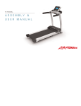
A S S E M B LY
INSTRUCTIONS
X1 Cross-Trainer
Life Fitness offers a full line of premier fitness equipment for the home.
®
TOTA L - B O D Y E L L I P T I C A L C R O S S -T R A I N E R S | T R E A D M I L L S | L I F E C Y C L E E X E R C I S E B I K E S
S TA I R C L I M B E R S | G Y M S Y S T E M S
5 1 0 0 N. R I V E R R O A D, S C H I L L E R PA R K , I L L I N O I S 6 0 1 7 6
LIFEFITNESS.COM
© 2005 Life Fitness, a division of Brunswick Corporation. All rights reserved. Life Fitness is a registered trademarks of Brunswick
Corporation. Any use of this trademark, without the express written consent of Life Fitness is forbidden. 8116401 Rev A-2 (01/07)
X1 Cross-Trainer
Hardware List
Item
Qty
1
2
3
4
5
6
7
8
9
10
11
12
13
14
15
16
17
4
14
7
2
14
2
2
4
2
2
2
8
8
1
2
4
2
Description
67 mm Hex Head Bolt
Cap Washer
Hex Head Nut
30 mm Hex Head Bolt
Plastic Cover Caps
12 mm Phillips Screw
Large Flat Washer
Large Wave Washer
Flat Washer
Lock Washer
20 mm Hex Head Bolt
16 mm Phillips Screw
Lock Washer
90 mm Hex Head Bolt
81.5 mm Hex Head Bolt
12 mm Self Tapping Screw
12 mm Large Head Phillips Screw
1)
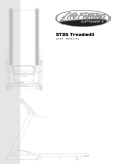
7. Lift the front end of the USER RIGHT PEDAL LEVER (M) to meet the USER RIGHT ROCKER ARM CLEVIS (T). Secure the PEDAL LEVER to the ROCKER ARM
CLEVIS using two CAP WASHERS (2), one 81.5 mm HEX HEAD BOLT (15), one NUT (3) and two PLASTIC COVER CAPS (5). Tighten the BOLT and NUT
securely. Repeat the procedure for the USER LEFT PEDAL LEVER (Q) and ROCKER ARM CLEVIS (U).
2)
8. Position the DISPLAY CONSOLE (V) over the DISPLAY CONSOLE MOUNTING PLATE (B) located at the top of the UPRIGHT TUBE ASSEMBLY (C). Plug the
CONNECTOR (W) and GROUNDING WIRE (Z) leading from the DISPLAY CONSOLE MOUNTING PLATE into the corresponding CONNECTOR(S) in the back of
the DISPLAY CONSOLE. Make sure the CONNECTOR(S) are full inserted. Push excess wire harness into the opening of the DISPLAY CONSOLE MOUNTING
PLATE.
4)
Secure the DISPLAY CONSOLE (V) to the DISPLAY CONSOLE MOUNTING PLATE (B) using four 12 mm SCREWS (16). Tighten the SCREWS securely.
CAUTION: Be careful not to pinch the wire harness when assembling the DISPLAY CONSOLE (V) to the DISPLAY CONSOLE MOUNTING PLATE (B).
9. Secure the WATER BOTTLE BRACKET (X) to the UPRIGHT TUBE ASSEMBLY (C) as shown using two 12 mm SCREWS (17). Tighten the SCREWS securely.
Insert the WATER BOTTLE (Y) into the WATER BOTTLE BRACKET.
6)
5)
3)
10. Refer to the "Getting Started" section of the User Manual for proper location, stabilizing, and POWER ADAPTER instructions.
11)
10)
9)
F
Assembly Guide:
5
Look for the number coded
hardware bags that match the
assembly sequence.
6
7)
7.
Pedal Lever &
Rocker Arm Assembly
5. & 6.
Pedals & Right Rear
Pedal Lever
1. & 2. & 3.
Levelers & Monocolumn
C
3
2
S
Q
P
N
8)
G
5
3
M
E
D
2
13
2
12)
13)
1
5
O
14
3)
5
T
2
2
5
R
A
15)
3)
4.
Pedal Arms
Physical Dimensions:
16)
8. & 9.
Console & Water Bottle
17)
V
B
10
15
3
S
14)
65 inches / 165 centimeters
27 inches / 68 centimeters
62 inches / 157 centimeters
204 pounds / 93 kilograms
5
U
2
4
Length:
Width:
Height:
Weight:
12
20
30
Tools required: Metric Socket set, Phillips Screwdriver, Metric Wrench set
40
50
60
70
80
90
100
110
120
130
140
150
160
C
Assembly Sequence
7
1. Position the base unit near the desired location for use (Refer to the "Getting Started" section of the User Manual for proper location). Locate and install the four
LEVELER FEET (A) into the front and rear stabilizers as shown.
2. With the DISPLAY CONSOLE MOUNTING PLATE (B) facing upward, lay the UPRIGHT TUBE ASSEMBLY (C) on floor in front of BASE FRAME (D). Cut the wire
tie securing the LOWER WIRE HARNESS (E) to the front of the BASE FRAME. Connect the UPPER WIRE HARNESS (F) to the LOWER WIRE HARNESS.
Position the UPRIGHT TUBE ASSEMBLY (C) between the plates on the front of the BASE FRAME (D). Feed any excess wire harness into the BASE FRAME. Tilt
the UPRIGHT TUBE ASSEMBLY into an upright position. Align the holes on the plates with the holes on the UPRIGHT TUBE ASSEMBLY. Secure the UPRIGHT
TUBE ASSEMBLY to the BASE FRAME using four 67 mm HEX HEAD BOLTS (1), eight CAP WASHERS (2) (4 on each side) and four NUTS (3). Leave BOLTS
loose at this time.
8
J
B
9
11
Z
W
H
10
Z
W
K
16
Using two 30 mm HEX HEAD BOLTS (4), secure the UPRIGHT TUBE ASSEMBLY (C) to the backside of the SUPPORT PLATE on the BASE FRAME (D). Tighten
the BOLTS securely. Tighten the previous four HEX HEAD BOLTS (1) securely. Install eight black PLASTIC COVER CAPS (5) over each 67 mm HEX HEAD BOLT
HEAD (1) and NUT (3).
3. Slide the tab of the UPRIGHT TUBE ANGLE BRACE (G) into the slot located near the base of the UPRIGHT TUBE ASSEMBLY (C) and pivot the UPRIGHT TUBE
ANGLE BRACE downward to met the BASE FRAME (D). Using two 12 mm SCREWS (6), secure the UPRIGHT TUBE ANGLE BRACE to the UPRIGHT TUBE
ASSEMBLY and BASE FRAME as shown.
Y
4. Slide one LARGE FLAT WASHER (7) and two LARGE WAVE WASHERS (8) onto the USER RIGHT PIVOT SHAFT (H). Slide the WASHERS fully over the PIVOT
SHAFT until seated against the pre-installed stop ring.
Locate the USER RIGHT ROCKER ARM ASSEMBLY (J) (Marked with an “R”). With the top handgrip facing the front of the unit (as shown), slide the USER RIGHT
ROCKER ARM ASSEMBLY onto the USER RIGHT PIVOT SHAFT (H) until seated against the WASHERS (7 & 8). Secure the ROCKER ARM ASSEMBLY to the
PIVOT SHAFT using one FLAT WASHER (9), LOCK WASHER (10), and 20 mm HEX HEAD BOLT (11). Tighten the BOLT securely. Insert one ROCKER ARM
END CAP (K) into the end of the ROCKER ARM SHAFT. Repeat the procedure for the USER LEFT ROCKER ARM ASSEMBLY (L).
5. Locate the USER RIGHT PEDAL LEVER (M) and PEDAL (N) (marked with an “R”). Position the PEDAL above the PEDAL MOUNTING PLATE (O) and secure the
PEDAL using four 16 mm SCREWS (12) and LOCK WASHERS (13). Tighten the SCREWS securely. Repeat for the USER LEFT PEDAL (P) and PEDAL LEVER
(Q).
6. Position the rear end of the USER RIGHT PEDAL LEVER (M) near the USER RIGHT REAR CLEVIS (R). Position the end of the PEDAL LEVER between the
clevis flanges. Align the holes and secure as shown using two CLEVIS COVERS (S), two CAP WASHERS (2), one 90 mm HEX HEAD BOLT (14), one NUT (3)
and two PLASTIC COVER CAPS (5). Tighten the BOLT and NUT securely.
X
C
17