1
CD00285859
Rev 2.4
IN APPROVAL
PAGE A
ft
STEVAL-ICB008V1 touch-sensing software library demonstration kit
based on STM8S207S8
-D
ra
Technical Literature
Alternate Identifier(s)
Key process
17987
Product Development
Dr
ISO Definition
aft
CUSTOM ATTRIBUTES
ft -
Confidentiality Level
Specification
Public
Technical Literature
Document Category
User manual
Dr
a
Document Type
Document Family
Original ID
Original Repository
Status
IN APPROVAL
Responsible
Keywords
Technical Literature, 17987, Product Development,
Specification, User manual, STEVAL-ICB008V1,
NOTICE: This document may have been revised since it was printed. Check Document Control System for latest version before using or copying.
© Copyright STMicroelectronics. Unauthorized reproduction and communication strictly prohibited.
DOCUMENT HISTORY
Version
Release Date
Change Qualifier
Rev 2.4
Product/Process change
Dr
a
ft -
Dr
aft
-D
ra
ft
Document revalidation. Board is obsolete but user manual could be useful for anyone who still has the
board. I propose to revalidate this cycle and inactivate at next revalidation cycle.
CD00285859
Rev 2.4
IN APPROVAL
PAGE C
DOCUMENT APPROVAL
USER FUNCTION
DATE
Camilleri Evelina
Document Controller
06-Feb-2014
Dr
a
ft -
Dr
aft
-D
ra
ft
LABEL
NOTICE: This document may have been revised since it was printed. Check Document Control System for latest version before using or copying.
© Copyright STMicroelectronics. Unauthorized reproduction and communication strictly prohibited.
Document CD00285859
2.4
Revision
IN APPROVAL
4 / 34
UM1002
User manual
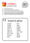
STEVAL-ICB008V1 touch-sensing software library
demonstration kit based on STM8S207S8
Introduction
This touch-sensing software library demonstration kit is based on STMicroelectronics' 8-bit
microcontroller STM8S207S8. With this kit, users can familiarize themselves with the
functionality and the performance of STMicroelectronics' capacitive touch-sensing solution.
This kit is driven by software open library at http://www.st.com/internet/mcu/subclass/1428.jsp.
ft
This is the complete, free source code to transform any 8-bit STM8 microcontroller into a
capacitive touchkey controller.
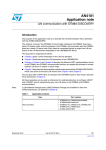
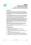
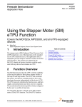
STM8S207S8 RC touch solution
Dr
a
ft -
Dr
Figure 1.
aft
-D
ra
The STEVAL-ICB008V1 demonstration kit consists of 3 parts, a demonstration board, a PC
GUI program, and a USB cable (standard-A to mini-B). Powered by the PC USB port, the
demonstration board can be demonstrated in standalone. There are 19 LEDs indicating
touchpad information for 6 keys (K1, K2, K3, K4, K5 and K6), 5 crosses (C, UP, LEFT,
DOWN and RIGHT) and one (5 electrodes) slider and another 3 LEDs on the board indicate
the system general status (power, system, and key). With the PC GUI program, the STM8S
RC touch solution provides a simple platform to monitor more detailed operating information
and configure values of critical touch-sensing parameters in applications.
December 2010
Doc ID 17987 Rev 2
1/31
www.st.com
Copyright STMicroelectronics
Company Internal
Unauthorized reproduction and communication strictly prohibited
Document CD00285859
2.4
Revision
IN APPROVAL
5 / 34
Contents
UM1002
Contents
Advantages of STM8S RC touch solution . . . . . . . . . . . . . . . . . . . . . . . . . 4
1.2
Architecture . . . . . . . . . . . . . . . . . . . . . . . . . . . . . . . . . . . . . . . . . . . . . . . . 4
Getting started with STM8S207S8 RC touch solution . . . . . . . . . . . . . . 6
2.1
Demonstration kit checklist . . . . . . . . . . . . . . . . . . . . . . . . . . . . . . . . . . . . . 6
2.2
Demonstration board description . . . . . . . . . . . . . . . . . . . . . . . . . . . . . . . . 6
PC GUI program . . . . . . . . . . . . . . . . . . . . . . . . . . . . . . . . . . . . . . . . . . . . 9
ft
3
1.1
3.1
Driver installation . . . . . . . . . . . . . . . . . . . . . . . . . . . . . . . . . . . . . . . . . . . . 9
3.2
PC GUI program . . . . . . . . . . . . . . . . . . . . . . . . . . . . . . . . . . . . . . . . . . . . 19
ra
2
General description . . . . . . . . . . . . . . . . . . . . . . . . . . . . . . . . . . . . . . . . . . 4
3.2.1
Main dialog . . . . . . . . . . . . . . . . . . . . . . . . . . . . . . . . . . . . . . . . . . . . . . 19
3.2.2
Configuration dialog . . . . . . . . . . . . . . . . . . . . . . . . . . . . . . . . . . . . . . . . 21
-D
1
aft
Appendix A Data format of log files . . . . . . . . . . . . . . . . . . . . . . . . . . . . . . . . . . . 25
Dr
Appendix B Schematics . . . . . . . . . . . . . . . . . . . . . . . . . . . . . . . . . . . . . . . . . . . . . 26
Dr
a
ft -
Revision history . . . . . . . . . . . . . . . . . . . . . . . . . . . . . . . . . . . . . . . . . . . . . . . . . . . . 30
2/31
Copyright STMicroelectronics
Doc ID 17987 Rev 2
Company Internal
Unauthorized reproduction and communication strictly prohibited
Document CD00285859
2.4
Revision
IN APPROVAL
6 / 34
UM1002
List of figures
List of figures
ft -
Dr
aft
-D
ra
ft
STM8S207S8 RC touch solution . . . . . . . . . . . . . . . . . . . . . . . . . . . . . . . . . . . . . . . . . . . . . 1
STM8S207S8 RC touch solution demonstration block diagram . . . . . . . . . . . . . . . . . . . . . . 4
STM8S207S8 RC touch board top view . . . . . . . . . . . . . . . . . . . . . . . . . . . . . . . . . . . . . . . . 6
STM8S207S8 RC touch board bottom view . . . . . . . . . . . . . . . . . . . . . . . . . . . . . . . . . . . . . 6
SWIM port pin bottom view . . . . . . . . . . . . . . . . . . . . . . . . . . . . . . . . . . . . . . . . . . . . . . . . . . 8
Driver installation step 1 . . . . . . . . . . . . . . . . . . . . . . . . . . . . . . . . . . . . . . . . . . . . . . . . . . . . 9
Driver installation step 2 . . . . . . . . . . . . . . . . . . . . . . . . . . . . . . . . . . . . . . . . . . . . . . . . . . . 10
Driver installation step 3 . . . . . . . . . . . . . . . . . . . . . . . . . . . . . . . . . . . . . . . . . . . . . . . . . . . 10
Driver installation step 4 . . . . . . . . . . . . . . . . . . . . . . . . . . . . . . . . . . . . . . . . . . . . . . . . . . . 11
Driver installation step 5 . . . . . . . . . . . . . . . . . . . . . . . . . . . . . . . . . . . . . . . . . . . . . . . . . . . 11
Driver installation step 6 . . . . . . . . . . . . . . . . . . . . . . . . . . . . . . . . . . . . . . . . . . . . . . . . . . . 12
Driver installation step 7 . . . . . . . . . . . . . . . . . . . . . . . . . . . . . . . . . . . . . . . . . . . . . . . . . . . 12
Driver installation step 8 . . . . . . . . . . . . . . . . . . . . . . . . . . . . . . . . . . . . . . . . . . . . . . . . . . . 13
Driver installation step 9 . . . . . . . . . . . . . . . . . . . . . . . . . . . . . . . . . . . . . . . . . . . . . . . . . . . 13
Driver installation step 10 . . . . . . . . . . . . . . . . . . . . . . . . . . . . . . . . . . . . . . . . . . . . . . . . . . 14
Driver installation step 11 . . . . . . . . . . . . . . . . . . . . . . . . . . . . . . . . . . . . . . . . . . . . . . . . . . 14
Driver installation step 12 . . . . . . . . . . . . . . . . . . . . . . . . . . . . . . . . . . . . . . . . . . . . . . . . . . 15
Driver installation step 13 . . . . . . . . . . . . . . . . . . . . . . . . . . . . . . . . . . . . . . . . . . . . . . . . . . 15
Driver installation step 14 . . . . . . . . . . . . . . . . . . . . . . . . . . . . . . . . . . . . . . . . . . . . . . . . . . 16
Driver installation step 15 . . . . . . . . . . . . . . . . . . . . . . . . . . . . . . . . . . . . . . . . . . . . . . . . . . 16
Driver installation step 16 . . . . . . . . . . . . . . . . . . . . . . . . . . . . . . . . . . . . . . . . . . . . . . . . . . 17
Driver installation step 17 . . . . . . . . . . . . . . . . . . . . . . . . . . . . . . . . . . . . . . . . . . . . . . . . . . 17
Driver installation step 18 . . . . . . . . . . . . . . . . . . . . . . . . . . . . . . . . . . . . . . . . . . . . . . . . . . 18
PC GUI main dialog . . . . . . . . . . . . . . . . . . . . . . . . . . . . . . . . . . . . . . . . . . . . . . . . . . . . . . 19
PC GUI configuration dialog . . . . . . . . . . . . . . . . . . . . . . . . . . . . . . . . . . . . . . . . . . . . . . . . 21
Pop-up box for successful reading operation from demonstration board . . . . . . . . . . . . . . 23
Pop-up box for successful writing operation to demonstration board . . . . . . . . . . . . . . . . . 24
LED indication circuit . . . . . . . . . . . . . . . . . . . . . . . . . . . . . . . . . . . . . . . . . . . . . . . . . . . . . 26
Touch key and driven shield . . . . . . . . . . . . . . . . . . . . . . . . . . . . . . . . . . . . . . . . . . . . . . . . 27
MCU and USB to UART . . . . . . . . . . . . . . . . . . . . . . . . . . . . . . . . . . . . . . . . . . . . . . . . . . . 28
Power supply +5 V and +3.3 V . . . . . . . . . . . . . . . . . . . . . . . . . . . . . . . . . . . . . . . . . . . . . . 29
LED indicator . . . . . . . . . . . . . . . . . . . . . . . . . . . . . . . . . . . . . . . . . . . . . . . . . . . . . . . . . . . 29
Dr
a
Figure 1.
Figure 2.
Figure 3.
Figure 4.
Figure 5.
Figure 6.
Figure 7.
Figure 8.
Figure 9.
Figure 10.
Figure 11.
Figure 12.
Figure 13.
Figure 14.
Figure 15.
Figure 16.
Figure 17.
Figure 18.
Figure 19.
Figure 20.
Figure 21.
Figure 22.
Figure 23.
Figure 24.
Figure 25.
Figure 26.
Figure 27.
Figure 28.
Figure 29.
Figure 30.
Figure 31.
Figure 32.
Doc ID 17987 Rev 2
Copyright STMicroelectronics
Company Internal
3/31
Unauthorized reproduction and communication strictly prohibited
Document CD00285859
2.4
Revision
IN APPROVAL
7 / 34
General description
UM1002
1
General description
1.1
Advantages of STM8S RC touch solution
Small outline with high density demonstration functions
●
Easy demonstration kit which is powered by a USB port, additional power supply is not
required
●
Two demonstration modes, offline and online
●
Board functions are driven by the library which can be configured through the GUI
●
Touchpad information logs on PC
●
SWIM port is reserved for debug use.
Architecture
ft
1.2
●
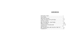
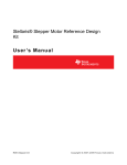
STM8S207S8 RC touch solution demonstration block diagram
Dr
a
ft -
Dr
aft
Figure 2.
-D
ra
A block diagram of the STM8S207S8 RC touch solution demonstration is illustrated in
Figure 2, and contains a demonstration board, a PC GUI program, and a standard-A to miniB USB cable. The kit can be used in standalone (offline mode), or used along with the PC
GUI program (online mode) for advanced demonstration.
In offline mode, the board is connected to the PC and the USB cable provides the power. By
touching each touchpad on the board, the corresponding LED on the board indicates the
touch-sensing status.
In online mode, the USB cable not only provides power supply to the demonstration board
but also data transform. Therefore, the USB driver needs to be installed prior to starting
communication. Thanks to the PC GUI program, some detailed information can be real-time
displayed or saved to the PC. Some critical configurations (e.g. threshold, de-bounce filter,
etc.) are able to be set to the board without entering the debugging procedure, and effected
immediately after setting is done through the PC GUI.
4/31
Copyright STMicroelectronics
Doc ID 17987 Rev 2
Company Internal
Unauthorized reproduction and communication strictly prohibited
Document CD00285859
2.4
Revision
IN APPROVAL
8 / 34
UM1002
General description
There is a reserved SWIM port, shown in Figure 2. The configuration between the debugger
is indicated by dashed arrows. This configuration is used to perform real-time debug, or
modify application firmware.
Recommended tools:
Debugger: resonance RLink debugger/programmer for ST microcontrollers. And STLink debugger and Flash programmer for STM8 and STM32 microcontrollers.
●
Development environment: ST MCU Toolset with ST visual develop (STVD) IDE and
ST visual programmer (STVP) programming interface.
Dr
a
ft -
Dr
aft
-D
ra
ft
●
Doc ID 17987 Rev 2
Copyright STMicroelectronics
Company Internal
5/31
Unauthorized reproduction and communication strictly prohibited
Document CD00285859
2.4
Revision
IN APPROVAL
9 / 34
Getting started with STM8S207S8 RC touch solution
UM1002
2
Getting started with STM8S207S8 RC touch solution
2.1
Demonstration kit checklist
The STM8S207S8 RC touch solution contains:
●
STM8S207S8 RC touch board
●
USB cable (standard-A to mini-B)
●
2.2
Material disc including PC GUI program “STM8S RC Touch Demo.exe”, USB driver
“CP210x_VCP_Win98SE.exe”, and user manual (this document).
Demonstration board description
ra
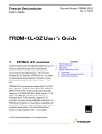
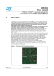
STM8S207S8 RC touch board top view
-D
Figure 3.
ft
Figure 3 shows the top view of the demonstration board and Figure 4 shows the bottom
view.
ft -
Dr
!-V
Dr
a
Figure 4.
aft
STM8S207S8 RC touch board bottom view
6/31
Copyright STMicroelectronics
!-V
Doc ID 17987 Rev 2
Company Internal
Unauthorized reproduction and communication strictly prohibited
Document CD00285859
2.4
Revision
UM1002
IN APPROVAL
10 / 34
Getting started with STM8S207S8 RC touch solution
Board description
1.
2.
System status indication LEDs
–
Power indicator illuminates once the board is powered. The power is obtained
through the USB cable
–
System indicator blinks with 1 Hz rate when microprocessor is working. The
blinking rate slows down when MCU enters low power mode
–
Key indicator illuminates once the key, slider, or cross direction touching has been
detected. Light is OFF when system has been reset
Key1~Key6
There is an indication LED inside each key electrode. Every touch event on Key1~Key6
toggles LED status. The LED lights ON and OFF correspond with key status.
3.
Slider
The slider consists of five electrodes, which are, from left to right, channel 0, channel 1,
channel 2, channel 3, and channel 4 respectively (refer to Figure 3 and Section 3.2.1).
The slider starts from the middle of the first electrode (channel 0) and ends up in the middle
of the fifth electrode (channel 4). Outside this area, the slider does not detect a position
change.
4.
-D
Note:
ra
ft
There are 8 indication LEDs above the electrodes displaying the current position of the
slider.
Cross keys
Dielectric
Dr
5.
aft
The center key has an indication LED inside the key electrode. Every touch on the
center key event toggles the LED status. The rest of the cross keys have their own LED
indicator near the electrode. Every touch event on those keys toggles the LED status.
The LED lights ON and OFF correspond with key status.
6.
ft -
Dielectric is a 1.5 mm thickness Plexiglas sheet, which is used to isolate the user's
finger from the electrode on the PCB. It can be replaced by another dielectric with a
different thickness or material, and some parameters (e.g. threshold) need to be tuned
through the PC GUI program. Please refer to the AN2869 application note.
MCU
7.
Dr
a
STM8S207S8, STMicroelectronics' standard 8-bit microprocessor.
SWIM port
The SWIM port is reserved for debug use. Please refer to Figure 5 for the pin
assignment.
Doc ID 17987 Rev 2
Copyright STMicroelectronics
Company Internal
7/31
Unauthorized reproduction and communication strictly prohibited
Document CD00285859
2.4
Revision
IN APPROVAL
11 / 34
Getting started with STM8S207S8 RC touch solution
Figure 5.
UM1002
SWIM port pin bottom view
N234
'.$
37)6$$
!-V
8.
USB connector
Dr
a
ft -
Dr
aft
-D
ra
ft
The USB connector is a mini-B receptacle for USB standard-A to mini-B cable.
8/31
Copyright STMicroelectronics
Doc ID 17987 Rev 2
Company Internal
Unauthorized reproduction and communication strictly prohibited
Document CD00285859
2.4
Revision
IN APPROVAL
12 / 34
UM1002
3
PC GUI program
PC GUI program
A PC GUI program named “STM8S RC Touch Demo.exe” is designed to demonstrate more
detailed information of the demonstration kit, such as signal level, reference level, etc. It also
provides an interface for the user to configure some critical parameters of RC touch directly
through the USB connection without reloading the firmware under debug mode.
3.1
Driver installation
Communication between the board and PC is achieved by a USB to UART bridge controller
CP2102 manufactured by Silicon Laboratories Inc. Before starting communication, a driver
needs to be installed on Windows®. Please follow the procedures below:
Step 1: run “CP210x_VCP_Win98SE.exe” in the disc, and click “Next” to proceed.
Driver installation step 1
Dr
a
ft -
Dr
aft
-D
ra
Figure 6.
ft
●
Doc ID 17987 Rev 2
Copyright STMicroelectronics
Company Internal
9/31
Unauthorized reproduction and communication strictly prohibited
Document CD00285859
2.4
Revision
IN APPROVAL
13 / 34
PC GUI program
●
UM1002
Step 2: accept the license agreement and click “Next” to proceed.
Driver installation step 2
Step 3: choose the installation directory and click “Next” to proceed. The default
directory is “c:\SiLabs\MCU\CP210x”.
Driver installation step 3
Dr
a
ft -
Dr
aft
Figure 8.
-D
●
ra
ft
Figure 7.
10/31
Copyright STMicroelectronics
Doc ID 17987 Rev 2
Company Internal
Unauthorized reproduction and communication strictly prohibited
Document CD00285859
2.4
Revision
IN APPROVAL
14 / 34
UM1002
PC GUI program
●
Step 4: click “Install” to proceed.
Driver installation step 4
Step 5: click “Finish” to exit installation program.
Dr
a
ft -
Dr
aft
Figure 10. Driver installation step 5
-D
●
ra
ft
Figure 9.
Doc ID 17987 Rev 2
Copyright STMicroelectronics
Company Internal
11/31
Unauthorized reproduction and communication strictly prohibited
Document CD00285859
2.4
Revision
IN APPROVAL
15 / 34
PC GUI program
●
UM1002
Step 6: connect the demonstration board to the PC with the USB cable. New hardware
is detected.
Figure 11. Driver installation step 6
Step 7: choose “No, not this time” in “Found New Hardware Wizard”, and click “Next” to
proceed.
ra
ft
●
Dr
a
ft -
Dr
aft
-D
Figure 12. Driver installation step 7
12/31
Copyright STMicroelectronics
Doc ID 17987 Rev 2
Company Internal
Unauthorized reproduction and communication strictly prohibited
Document CD00285859
2.4
Revision
IN APPROVAL
16 / 34
UM1002
PC GUI program
●
Step 8: choose “Install from a list or specific location (Advanced)”, and click “Next” to
proceed.
Step 9: browse the directory where the driver is installed, and click “Next” to proceed.
Dr
a
ft -
Dr
aft
Figure 14. Driver installation step 9
-D
●
ra
ft
Figure 13. Driver installation step 8
Doc ID 17987 Rev 2
Copyright STMicroelectronics
Company Internal
13/31
Unauthorized reproduction and communication strictly prohibited
Document CD00285859
2.4
Revision
IN APPROVAL
17 / 34
PC GUI program
●
UM1002
Step 10: install “CP210x USB Composite Device” by clicking “Continue Anyway”.
Step 11: click “Finish” to complete driver installation for “CP210x USB Composite
Device”.
Dr
a
ft -
Dr
aft
Figure 16. Driver installation step 11
-D
●
ra
ft
Figure 15. Driver installation step 10
14/31
Copyright STMicroelectronics
Doc ID 17987 Rev 2
Company Internal
Unauthorized reproduction and communication strictly prohibited
Document CD00285859
2.4
Revision
IN APPROVAL
18 / 34
UM1002
PC GUI program
●
Step 12: another new hardware is detected.
Figure 17. Driver installation step 12
Step 13: choose “No, not this time” in “Found New Hardware Wizard”, and click “Next”
to proceed.
ft
●
Dr
a
ft -
Dr
aft
-D
ra
Figure 18. Driver installation step 13
Doc ID 17987 Rev 2
Copyright STMicroelectronics
Company Internal
15/31
Unauthorized reproduction and communication strictly prohibited
Document CD00285859
2.4
Revision
IN APPROVAL
19 / 34
PC GUI program
●
UM1002
Step 14: choose “Install from a list or specific location (advanced)”, and click “Next” to
proceed.
Step 15: browse the directory where the driver is installed, and click “Next” to proceed.
Dr
a
ft -
Dr
aft
Figure 20. Driver installation step 15
-D
●
ra
ft
Figure 19. Driver installation step 14
16/31
Copyright STMicroelectronics
Doc ID 17987 Rev 2
Company Internal
Unauthorized reproduction and communication strictly prohibited
Document CD00285859
2.4
Revision
IN APPROVAL
20 / 34
UM1002
PC GUI program
●
Step 16: install “CP210x USB to UART Bridge Controller” by clicking “Continue
Anyway”.
Step 17: click “Finish” to complete driver installation for “CP210x USB to UART Bridge
Controller”.
Dr
a
ft -
Dr
aft
Figure 22. Driver installation step 17
-D
●
ra
ft
Figure 21. Driver installation step 16
Doc ID 17987 Rev 2
Copyright STMicroelectronics
Company Internal
17/31
Unauthorized reproduction and communication strictly prohibited
Document CD00285859
2.4
Revision
IN APPROVAL
21 / 34
PC GUI program
●
Note:
UM1002
Step 18: launch device manager (Path: My Computer → Properties → Hardware →
Device Manager) and expand “Ports (COM and LPT)” as shown in Figure 23. A virtual
COM port named “CP210x USB to UART Bridge Controller” is listed if the driver is
successfully installed. The port number is assigned by Windows automatically (or
reassigned manually).
Never assign a number exceeding 8, otherwise the PC GUI program is not able to recognize
the COM port correctly.
Dr
a
ft -
Dr
aft
-D
ra
ft
Figure 23. Driver installation step 18
18/31
Copyright STMicroelectronics
Doc ID 17987 Rev 2
Company Internal
Unauthorized reproduction and communication strictly prohibited
Document CD00285859
2.4
Revision
IN APPROVAL
22 / 34
UM1002
3.2
PC GUI program
PC GUI program
Before running the PC GUI program, make sure the driver is properly installed, and the USB
cable is well connected.
3.2.1
Main dialog
Run “STM8S RC Touch Demo.exe”. The main dialog program is illustrated in Figure 24.
Figure 24. PC GUI main dialog
ra
ft
-D
aft
Dr
!-V
ft -
Main dialog layout
1.
Communication setting
2.
Dr
a
After choosing the virtual COM port listed in “Device Manager” (Figure 23), the button
is used to open or close the port. The LED icon turns on (green) to indicate that the port
is opened. When the port is not opened, the LED icon turns off (gray). Make sure the
virtual COM port has been recognized before the PC GUI program is opened.
Otherwise the port is not displayed in the dropdown list.
Data logging
Data logging is used to record events regarding touch-sensing. Of course, some
unexpected touching or system status change due to environmental conditions is
captured by the data logging function. Simple mode records only touch/release events
and the slider position changing events. However, full mode records all touch-sensing
information received from the demonstration board.
Data is saved in “STM8S RC Touch Demo_Simple.log” and “STM8S RC Touch
Demo_Full.log” respectively, which are located in the same directory as the PC GUI
Doc ID 17987 Rev 2
Copyright STMicroelectronics
Company Internal
19/31
Unauthorized reproduction and communication strictly prohibited
Document CD00285859
2.4
Revision
IN APPROVAL
23 / 34
PC GUI program
UM1002
program. It is recommended to open the log files with Windows Excel. The record
format is described in Appendix A.
3.
System configuration
Press the “Configuration” button to launch a configuration dialog which is described in
Section 3.2.2.
4.
Slider position
The current position of the slider bar is indicated by this number.
5.
Slider illustration
The current position of the slider bar is indicated by this illustration.
6.
Slider touch-sensing information
The information is obtained from electrode pads Ch0, Ch1, Ch2, Ch3 and Ch4.
“Sig” stands for signal level. The number shows present charging time to those
channels
–
“Ref” stands for reference level. The number shows judgment benchmark of a
touch event. Normally, a signal is not less than the sum of the reference level. The
detected touch events are treated as valid
–
“NRC” stands for noise rejection counter. During each IO acquisition, NRC
increases by 1. The MCU detects an incorrect measure once signal presence is
out of guard band
Cross touch-sensing information
-D
7.
ra
ft
–
8.
aft
The information is obtained from electrode pads up, down, left, right, and center. The
meaning of the table content of sig, ref, and NRC is the same as “slider touch-sensing
information”.
Cross illustration
Key touch-sensing information
ft -
9.
Dr
With each touch of cross keys, the corresponding icon changes color. For the center
key the icon changes to red. For the direction keys the icon changes to blue. If no touch
is detected, the icon remains gray.
Dr
a
The information is obtained from electrode pads Key1, Key2, Key3, Key4, Key5, and
Key6. The meaning of the table content is the same as slider touch-sensing
information.
10. Key illustration
Once a touch of the Key electrode is detected, the corresponding icon turns to red. If no
touch of the key is detected, the icon remains gray.
20/31
Copyright STMicroelectronics
Doc ID 17987 Rev 2
Company Internal
Unauthorized reproduction and communication strictly prohibited
Document CD00285859
2.4
Revision
IN APPROVAL
24 / 34
UM1002
3.2.2
PC GUI program
Configuration dialog
-D
ra
ft
Figure 25. PC GUI configuration dialog
Configuration Parameters
1.
Detection Timeout
2.
Dr
aft
This feature enables a counter per key to set a maximum time for one detection
process. If a key stays in detected state for this duration, the system launches a recalibration process. As a consequence, the key is no longer detected. This feature
avoids blocking the system in detected state due to unexpected external perturbations.
De-bounce filter
3.
Dr
a
ft -
The programmable filters require consecutive detections over a number of readings for
a touch to be confirmed. This is used during key detection, key end detection and
before entering the calibration state. A counter is set at the initialization state and
decremented at each state machine loop. When the value reaches 0, the next state is
reached. For instance, when the de-bounce filter is set to “2 Acqs”, it means that the
total number of acquisitions for verifying a key's state is 3 (2+1).
Low power mode
In order to save the average current consumption of the MCU this feature enables the
STM8S207S8 to enter into active halt mode between proceeding touch-sensing
routines. For instance, “8 mSec” means STM8S207S8 is in active halt for 8
milliseconds, and then wakes up for another touch-sensing routine.
On the other hand, in the low power mode, key response is consequently slowed down.
However, after a touch is detected, STM8S207S8 stays in run mode for a while (5
seconds). If no other touch is detected, STM8S207S8 once more returns to low power
mode.
When entering into low power mode, the indication LED “System”, on the
demonstration board, slows down its blinking frequency, and the refreshing rate of the
PC GUI program also decreases.
Doc ID 17987 Rev 2
Copyright STMicroelectronics
Company Internal
21/31
Unauthorized reproduction and communication strictly prohibited
Document CD00285859
2.4
Revision
IN APPROVAL
25 / 34
PC GUI program
Note:
UM1002
Do NOT try to configure the demonstration board when it is in low power mode, as
STM8S207S8 cannot receive data properly during active halt mode.
4.
Slider resolution
Slider resolution defines the default resolution for multi-channel keys.
This parameter can take a value between 1 (1-bit resolution) and 8 (8-bit resolution). A
low value results in a low resolution and is less subject to noise. A high value results in
a high resolution and is more subject to noise.
For instance, if slider resolution is set to “4 bits”, the slider position ranges from 0 (20) to
15 (24-1).
5.
DES setting
The detection exclusion system (DES) is to prevent several keys from responding to a
single touch.
6.
ft
DES locks all keys of the same group in the untouched state once the first key of the
group is detected. The locking key must be released first for any other key of the group
to be reported as touched.
Automatic recovery
-D
ra
RC touch reads the RC charging time and sense capacitance variation when a key is
touched. If the charging time shows as too long or too short, RC touch sets the
corresponding key to error state, and stops the key from being detected. The key is
apparently “dead”.
7.
aft
If the causes (water film, electrical interference, etc.) of the abnormality are removed,
automatic recovery function resets the error state and resumes the function.
SC detect threshold
Dr
SC detect threshold defines the detection threshold value for the single-channel keys.
The key is determined as “detected” if the changed value is greater than this threshold.
8.
ft -
This parameter can take a value varying from 1 to 127. A low value results in high
sensitivity during the detection. A high value results in low sensitivity during the
detection.
SC end detect threshold
Dr
a
SC end detect threshold defines the end-detection threshold value for the singlechannel keys. The key is determined as “not detected” if the changed value is lower
than this threshold.
This parameter can take a value varying from 1 to 127. A low value results in low
sensitivity during the un-detection. A high value results in high sensitivity during the undetection.
9.
SC recalibration threshold
SC recalibration threshold defines the recalibration threshold value for the singlechannel keys. The key is recalibrated if the changed value is lower than this threshold.
This parameter can take a value varying from -1 to -128. A low absolute value results in
high sensitivity for the recalibration. A high absolute value results in low sensitivity for
the recalibration.
22/31
Copyright STMicroelectronics
Doc ID 17987 Rev 2
Company Internal
Unauthorized reproduction and communication strictly prohibited
Document CD00285859
2.4
Revision
IN APPROVAL
26 / 34
UM1002
PC GUI program
10. MC detect threshold
The dialog box shows the detect threshold for multi-channel keys. The parameter
setting is the same as the SC detect threshold.
11. MC end detect threshold
The dialog box shows the end detect threshold value for multi-channel keys. The
parameter setting is the same as the SC end detect threshold.
12. MC recalibration threshold
The dialog box shows the recalibration threshold value for multi-channel keys. The
parameter setting is the same as the SC recalibration threshold.
Action buttons description
1.
Read configuration from board
ft
After pressing this button, all the 12 configuration parameters, described above in
Configuration Parameters, are loaded to the current dialog box from the demonstration
board. A pop-up box (in Figure 26) shows that the operation is successful.
Dr
aft
-D
ra
Figure 26. Pop-up box for successful reading operation from demonstration board
Save configuration to board
ft -
2.
Dr
a
After pressing this button, all the 12 configuration parameters described in
Configuration Parameters are loaded to the demonstration board from the current
dialog.
A pop-up box (in Figure 27) shows the operation is successful.
Doc ID 17987 Rev 2
Copyright STMicroelectronics
Company Internal
23/31
Unauthorized reproduction and communication strictly prohibited
Document CD00285859
2.4
Revision
IN APPROVAL
27 / 34
PC GUI program
UM1002
Figure 27. Pop-up box for successful writing operation to demonstration board
3.
Read configuration from PC
ft
After pressing this button, all the 12 configuration parameters described in
Configuration Parameters are loaded to the demonstration board from the file “STM8S
RC Touch Demo.ini”, if present.
4.
ra
Make sure that the “STM8S RC Touch Demo.ini” file is located in the same directory as
the PC GUI program.
Save configuration to PC
-D
After pressing this button, all the 12 configuration parameters described in
Configuration Parameters are saved in the file “STM8S RC Touch Demo.ini” from the
demonstration board.
Dr
a
ft -
Dr
aft
The saved file “STM8S RC Touch Demo.ini” is located in the same directory as the PC
GUI program.
24/31
Copyright STMicroelectronics
Doc ID 17987 Rev 2
Company Internal
Unauthorized reproduction and communication strictly prohibited
Document CD00285859
2.4
Revision
IN APPROVAL
28 / 34
UM1002
Data format of log files
Appendix A
Data format of log files
Simple logging mode
The data format of “STM8S RC Touch Demo_Simple.log” is organized below in Table 1.
Table 1.
Data format of “STM8S RC Touch Demo_Simple.log”
A
B
C
D
Date
Time
Key name
Key status(1)
1. Key status: touched/released for Key1~Key6 and cross keys; slider position for slider.
Full logging mode
Data format of “STM8S RC Touch Demo_Full.log” for Key1~Key6 and
Cross
-D
Table 2.
ra
ft
The data format of “STM8S RC Touch Demo_Full.log” is organized in Table 2, and 3.
A
B
C
D
Date
Time
Key name
Key status
E
F
G
H
Signal
level
Reference
level
NRC
LED
status(1)
Table 3.
Dr
aft
1. LED status: status of indicative LEDs on the demonstration board is not available for up, left, down, and
right.
Data format of “STM8S RC Touch Demo_Full.log” for Slider
Date
Reference level (Ch0)
O
NRC (Ch2)
B
Time
I
NRC (Ch0)
P
Signal level (Ch3)
C
Key name
J
Signal level (Ch1)
Q
Reference level (Ch3)
Position
K
Reference level (Ch1)
R
NRC (Ch3)
UnScaled
position(1)
L
NRC (Ch1)
S
Signal level (Ch4)
F
Slider resolution
M
Signal level (Ch2)
T
Reference level (Ch4)
G
Signal level
(Ch0)
N
Reference level (Ch2)
U
NRC (Ch4)
E
Dr
a
D
H
ft -
A
1. UnScaled position: RC touch always calculates a raw position of 8-bit resolution ranging form 0 to 255, and
then converts it to position information according to slider resolution.
In full logging mode, each record value is saved in Key1 → Key2 → Key3 → Key4 → Key5 →
Key6 → Up → Left → Down → Right → Center → Slider.
Doc ID 17987 Rev 2
Copyright STMicroelectronics
Company Internal
25/31
Unauthorized reproduction and communication strictly prohibited
26/31
Copyright STMicroelectronics
Company Internal
*1'
'9
/('B6/ '5
*1'
*1'
*1'
&
Q)9
&
Q)9
&
Q)9
&
Q)9
%/ 8(
'
%/ 8(
'
%/ 8(
'
%/ 8(
'
/('B. /('B. /('B. /('B. *1'
*1'
*1'
*1'
*1'
*1'
&
Q)9
&
Q)9
&
Q)9
&
Q)9
&
Q)9
&
Q)9
/('B6<67(
0
/('B728&
+
%/ 8(
'
'9
/('B. /('B. /('B. 4
.
5
/('B6<67(
0
.
5
/('B728&
+
*1'
*1'
1
&
Q)9
&
Q)9
/('B'2:
1
1
*1'
4
*1'
/('B5,*+7
.
5
/('B. .
5
/('B. .
5
/('B. ft
ra
-D
%/ 8(
'
%/ 8(
'
%/ 8(
'
%/ 8(
'
%/ 8(
'
aft
Dr
/('B. /('B/ ()7
/('B&(17(
5
ft /('B. /('B/ ()7
/('B&(17(
5
Dr
a
%/ 8(
'
%/ 8(
'
%/ 8(
/('B83
5('
'
*5((
1
'
5('
'
/('B'2:
1
/('B5,*+7
4
1
4
1
4
1
.
5
.
5
.
5
*1'
*1'
'9
&
Q)9
&
Q)9
&
Q)9
%/ 8(
'
&
Q)9
%/ 8(
'
&
Q)9
%/ 8(
'
3RZHU
6\VWHP
.H\
%/ 8(
'
%/ 8(
'
.
5
.
5
.
5
'9
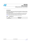
Schematics
*1'
'9
/('B6/ '5
/('B6/ '5
*1'
*1'
&
Q)9
&
Q)9
&
Q)9
/('B83
,QGLFDWRU IRU &URVV
2.4
/('B6/ '5
/('B6/ '5
/('B6/ '5
*1'
*1'
*1'
'
%/ 8(
'9
,QGLFDWRU IRU .H\V
Revision
/('B6/ '5
/('B6/ '5
/('B6/ '5
/('B6/ '5
/('B6/ '5
/('B6/ '5
&
Q)9
'
Appendix B
/('B6/ '5
/('B6/ '5
/('B6/ '5
,QGLFDWRU IRU 6OLGHU
Document CD00285859
IN APPROVAL
29 / 34
UM1002
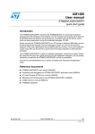
Schematics
Figure 28. LED indication circuit
!-V
Doc ID 17987 Rev 2
Unauthorized reproduction and communication strictly prohibited
Document CD00285859
2.4
Revision
IN APPROVAL
30 / 34
UM1002
Schematics
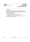
Figure 29. Touch key and driven shield
R1
K6
K5
K4
K3
K2
K1
R2
1M
10K
R3
R4
1M
10K
R5
R6
1M
10K
R7
R8
1M
10K
R9
R10
1M
10K
R11
R12
1M
K EY6
K EY5
K EY4
K EY3
K EY2
K EY1
ra
R13
1M
R14
UP
10K
R16
1M
10K
R17
R18
1M
10K
R19
L EF T
Dr
ft -
DOWN
aft
RI GHT
R20
1M
10K
R21
R22
1M
CROSS_UP
CROSS_CENTER
CROSS_L EF T
CROSS_DOWN
10K
R23
3.3M
R24
10K
SL DR1
Dr
a
CROSS_RI GHT
R15
-D
C
ft
10K
SL DR2
SL DR3
SL DR4
SL IDER1
R25
R26
3.3M
10K
R27
R28
3.3M
10K
R29
R30
3.3M
10K
R31
R32
3.3M
SL IDER2
SL IDER3
SL IDER4
SL IDER5
10K
SL DR5
L OAD
Copper SHIEL D on board
R34
SHI EL D
SH_DRV
0
C14
1nF/16V
GND
R33
10K
R37
0
R38
0
R39
0
R54
0
PA_DRVSHD
PB_DRVSHD
PC_DRVSHD
PE_DRVSHD
AM06713v1
Doc ID 17987 Rev 2
Copyright STMicroelectronics
Company Internal
27/31
Unauthorized reproduction and communication strictly prohibited
Document
Document
CD00285859
2.4
Revision
Revision
31 / 34
IN APPROVAL
UM1002
Figure 30. MCU and USB to UART
MCU
VDD_MCU
USB to UART
R40
4.7K
9
8
V B US
NC
R ST
10
12
11
SUSPE ND
NC
SUSPE ND
aft
14
Dr
D+
NC
GND
-D
SWI M
36
PE_DRVSHD
35
CL K
R50
51K
R43
0
R51
51K
R42
7
6
VDD_USB
5
1
4
2
3
C6
0.1uF/16V
I/O1
3
I/O2
DT R
1
aft
5
1
2
3
4
5
DD+
4
CN5(M)
GND
CN2
0
1
2
3
4
VDD_MCU
SWI M
CN3
SWI M
NRST
R49
10K
I/O2
6
C34
1uF/16V
SDA
R48
10K
I/O1
USBL C6-2SC6
2
R44
10K
GND
CN1
TVS1
GND VBUS
28
TX D
DSR
27
26
22
L ED_SYSTEM
L ED_TOUCH
DCD
RXD
NC
L ED_K 1
37
RI
25
L ED_K 2
21
NC
CTS
41
34
NC
RTS
UART_TX
38
D-
ft -
UART_RX
39
Vdd
NC
ra
43
42
40
20
L ED_K 3
NC
NC
NR ST
44
D5V
REGI N
VDD_MCU
1
2
3
4
SWI M
PG 1
GND
33
32
Dr
PG 0
PE2 (T)/I 2C_SDA
L OA D
PC 6 (HS)/SPI _M OSI
PC 7 (HS)/SPI _M I SO
31
30
23
C R OSS_DOW N
13
NC
1
2
OSC I N/PA 1
4
3
V ssio_1
OSC OUT /PA 2
5
V ss
6
7
V dd
V CAP
V ddio_1
PE1 (T)/I 2C_SCL
AI N9/PE6
NC
23
NR ST
OE
LE
1uF/16V
K EY 1
8
9
U A R T 1_R X /(HS) PA 4
11
10
[TI M1_CH1N] AI N0/PB0
PC _DR V SHD
22
PE0 (HS)/CL K _CCO
PE 5/SPI _NSS
CROSS_L EF T
[TI M1_CH2N] AI N1/PB1
SL I DE R 1
21
PD0 (HS)/TI M3_CH2 [TI M1_BK IN] [ CLK _CCO]
V ddio_2
PB_DRVSHD
PD1 (HS)/SWI M
[TI M1_CH3N] AI N2/PB2
29
20
[TI M1_ETR] AI N3/PB3
V ssio_2
CROSS_CENTER
PD2 (HS)/TI M3_CH1 [TI M2_CH3]
28
19
PD3(HS)/TI M2_CH2 [ADC_ETR]
[I 2C_SCL ] AIN4/PB4
PC 5 (HS)/SPI _SC K
CROSS_UP
[I 2C_SDA] AI N5/PB5
PC 3 (HS)/TI M 1_C H3
18
PD4 (HS)/TI M2_CH1 [BEEP ]
27
CROSS_RI GHT
AI N6/PB6
SL I DE R 2
17
19
PD5/UART3_TX
26
16
K EY6
18
PD7/TL 8 [TIM1_CH4]
SL I DE R 3
K EY5
17
PD6/UART3_RX
PC 2 (HS)/TI M 1_C H2
15
16
AI N7/PB7
25
K EY4
10K
Vssa
SL I DE R 4
14
PC 1 (HS)/TI M 1_C H1
13
K EY3
Vdda
24
Doc ID 17987 Rev 2
GND
U2
CP 2102
VDD_MCU
15
SL I DE R 5
12
K EY 2
PA _DR V SHD
C7
0.1uF/16V
R52
10K
C4
10nF/16V
C5
R41
U A R T 1_T X /(HS) PA 5
VDD_MCU
GND
GND
GND
UA R T 1_C K /(HS) PA 6
U1
STM8S207S8 / STM8S105S8
C1
10nF/16V
C2
0.1uF/16V
C3
0.1uF/16V
24
VDD_MCU
R53
10K
GND
VDD_MCU
GND
28/31
Copyright STMicroelectronics
AM06714v1
Company Internal
Schematics
C12
0.1uF/16V
Unauthorized reproduction and communication strictly prohibited
Copyright STMicroelectronics
3
4
5
6
7
8
9
10
11
12
CL K
LE
L ED_CENTER
Company Internal
L ED_L EF T
L ED_UP
L ED_K 4
L ED_K 5
Doc ID 17987 Rev 2
L ED_K 6
L ED_RI GHT
L ED_DOWN
OUT7
OUT6
OUT5
OUT8
OUT9
OUT10
OUT11
OUT12
13 L ED_SL DR1
14 L ED_SL DR2
15 L ED_SL DR3
16 L ED_SL DR4
17 L ED_SL DR5
18 L ED_SL DR6
GND
STM8S_RCTouch_Dem o_Sch_2.SchDoc
GND
ft
ra
-D
GND
D5V
1
GND
OUT4
OUT13
aft
Dr
D5V
OUT
OUT3
OUT2
19 L ED_SL DR7
R45
10K
OE
L ED_SL DR1
L ED_SL DR2
L ED_SL DR3
L ED_SL DR4
L ED_SL DR5
L ED_SL DR6
L ED_SL DR7
L ED_SL DR8
L ED_K 1
L ED_K 2
L ED_K 3
L ED_K 4
L ED_K 5
L ED_K 6
L ED_TOUCH
L ED_SYSTEM
L ED_RI GHT
L ED_DOWN
L ED_UP
L ED_CENTER
L ED_L EF T
L ED Indicator Section
IN
OUT14
20 L ED_SL DR8
13K
GND
L ED_SL DR1
L ED_SL DR2
L ED_SL DR3
L ED_SL DR4
L ED_SL DR5
L ED_SL DR6
L ED_SL DR7
L ED_SL DR8
L ED_K 1
L ED_K 2
L ED_K 3
L ED_K 4
L ED_K 5
L ED_K 6
L ED_TOUCH
L ED_SYSTEM
L ED_RI GHT
L ED_DOWN
L ED_UP
L ED_CENTER
L ED_L EF T
2.4
OUT1
OE
OUT15
21
22
R46
ft -
C13
22uF/16V
C11
0.1uF/16V
OUT0
SDO
23
24
3
LE
CL K
R- EXT
VDD
+
SDI
GND
STP 16CP05XTTR
C35
0.1uF/16V
+
2
1
VDD_MCU
C8
22uF/16V
Revision
SDA
GND
U3
Dr
a
Document CD00285859
IN APPROVAL
32 / 34
UM1002
Schematics
Figure 31. Power supply +5 V and +3.3 V
D5V
U4
2
VDD_MCU
C10
0.1uF/16V
+
GND
C9
22uF/16V
L D1117S33CTR
AM06717v1
Figure 32. LED indicator
AM06715v1
29/31
Unauthorized reproduction and communication strictly prohibited
Document CD00285859
2.4
Revision
IN APPROVAL
33 / 34
Revision history
UM1002
Revision history
Table 4.
Document revision history
Revision
Changes
16-Nov-2010
1
Initial release.
14-Dec-2010
2
Added: Appendix B: Schematics
Dr
a
ft -
Dr
aft
-D
ra
ft
Date
30/31
Copyright STMicroelectronics
Doc ID 17987 Rev 2
Company Internal
Unauthorized reproduction and communication strictly prohibited
Document CD00285859
2.4
Revision
IN APPROVAL
34 / 34
UM1002
Please Read Carefully:
ra
ft
Information in this document is provided solely in connection with ST products. STMicroelectronics NV and its subsidiaries (“ST”) reserve the
right to make changes, corrections, modifications or improvements, to this document, and the products and services described herein at any
time, without notice.
All ST products are sold pursuant to ST’s terms and conditions of sale.
-D
Purchasers are solely responsible for the choice, selection and use of the ST products and services described herein, and ST assumes no
liability whatsoever relating to the choice, selection or use of the ST products and services described herein.
aft
No license, express or implied, by estoppel or otherwise, to any intellectual property rights is granted under this document. If any part of this
document refers to any third party products or services it shall not be deemed a license grant by ST for the use of such third party products
or services, or any intellectual property contained therein or considered as a warranty covering the use in any manner whatsoever of such
third party products or services or any intellectual property contained therein.
Dr
UNLESS OTHERWISE SET FORTH IN ST’S TERMS AND CONDITIONS OF SALE ST DISCLAIMS ANY EXPRESS OR IMPLIED
WARRANTY WITH RESPECT TO THE USE AND/OR SALE OF ST PRODUCTS INCLUDING WITHOUT LIMITATION IMPLIED
WARRANTIES OF MERCHANTABILITY, FITNESS FOR A PARTICULAR PURPOSE (AND THEIR EQUIVALENTS UNDER THE LAWS
OF ANY JURISDICTION), OR INFRINGEMENT OF ANY PATENT, COPYRIGHT OR OTHER INTELLECTUAL PROPERTY RIGHT.
Dr
a
ft -
UNLESS EXPRESSLY APPROVED IN WRITING BY AN AUTHORIZED ST REPRESENTATIVE, ST PRODUCTS ARE NOT
RECOMMENDED, AUTHORIZED OR WARRANTED FOR USE IN MILITARY, AIR CRAFT, SPACE, LIFE SAVING, OR LIFE SUSTAINING
APPLICATIONS, NOR IN PRODUCTS OR SYSTEMS WHERE FAILURE OR MALFUNCTION MAY RESULT IN PERSONAL INJURY,
DEATH, OR SEVERE PROPERTY OR ENVIRONMENTAL DAMAGE. ST PRODUCTS WHICH ARE NOT SPECIFIED AS "AUTOMOTIVE
GRADE" MAY ONLY BE USED IN AUTOMOTIVE APPLICATIONS AT USER’S OWN RISK.
Resale of ST products with provisions different from the statements and/or technical features set forth in this document shall immediately void
any warranty granted by ST for the ST product or service described herein and shall not create or extend in any manner whatsoever, any
liability of ST.
ST and the ST logo are trademarks or registered trademarks of ST in various countries.
Information in this document supersedes and replaces all information previously supplied.
The ST logo is a registered trademark of STMicroelectronics. All other names are the property of their respective owners.
© 2010 STMicroelectronics - All rights reserved
STMicroelectronics group of companies
Australia - Belgium - Brazil - Canada - China - Czech Republic - Finland - France - Germany - Hong Kong - India - Israel - Italy - Japan Malaysia - Malta - Morocco - Philippines - Singapore - Spain - Sweden - Switzerland - United Kingdom - United States of America
www.st.com
Doc ID 17987 Rev 2
Copyright STMicroelectronics
Company Internal
31/31
Unauthorized reproduction and communication strictly prohibited