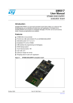
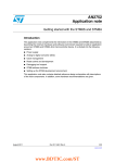
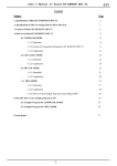
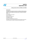
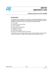
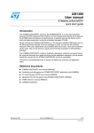
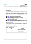
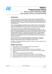
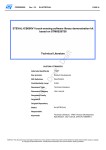
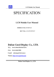
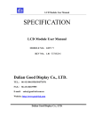
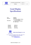
1
User’s Manual of Board ET-BASE STM8S208/ ET-STM8S STAMP ET-BASE STM8S208/ET-STM8S STAMP 1. Specifications of Board ET-BASE STM8S208/ET-STM8S STAMP - Use 3.3V-5V VDC Power Supply for Board ET-STM8S STAMP and 5V VDC Power Supply for Board ET-BASE STM8S208. - Run MCU at 3.3V-5V VDC - Run Frequency MCU 24MHz(Crystal) for External Clock(On Board) - Run Frequency MCU 128KHz–16MHz(RC Oscillator) for Internal Clock (Default) - Have 128Kbyte Flash Memory, 6Kbyte RAM - Serial Interface consists of CAN = 1-Channel, SPI = 1-Channel, UART = 2-Channel, I2C = 1-Channel. - MCU LQFP80 DIP Type has 80PIN in total; in this case, there are 68PIN I/O(PORT PA-PI). - Can 10,000 times re-program - Have 16BIT Timer = 3-Channel, 8BIT Timer = 1-Channel - Have ADC 10BIT Converter, Input 16-Channel - Have Slot Micro SD Card (for ET-Base STM8S208) - Use C Language to develop program; in this case, it uses Program ST Visual Develop to be Editor and Program Cosmic CxSTM8 to be Compiler. It is 16Kbyte free; if registered through website, user got 32Kbyte free. Please follow the instructions in the manual. - Use Tool ST-Link or STM8S-DISCOVERY to be the operator through Connector SWIM on board to Download and Debug program, including Set Option Byte for MCU - If user only downloads, it can download program through RS232 at Connector UART1 of board; in this case, it uses Program Flash Loader Demonstrator (be compatible with version “ET-BASE STM8S208”). ETT CO.,LTD -1- WWW.ETT.CO.TH User’s Manual of Board ET-BASE STM8S208/ ET-STM8S STAMP 2. Structure of Board ET-BASE STM8S208/ET-STM8S STAMP PC0 PC2 PC4 VSS PC6 PG0 PG2 PG4 PI1 PI3 PI5 PG6 PE4 PE2 PE0 PI7 PD1 PD3 PD5 PD7 1.I/O PIN 0. 1 ET -S TM 8S 5.VIN 22pF 1M 22pF 51R 0.1 10K 0.1 0. 1 47 0. 0n 1 1K VDD SWIM GND RST 8 20 8S M 6B ST BT M 3.Download 6.LED-PWR 1K ST AM P PE5 PC1 PC3 PC5 VDD PC7 PG1 PG3 PI0 PI2 PI4 PG5 PG7 PE3 PE1 PI6 PD0 PD2 PD4 PD6 2.SW.RESET 4.LED-PH0 PE6 PH7 PH5 PB0 PB2 PB4 PB6 PF0 VSS REF+ PF4 PF6 PH3 PH1 PA6 PA4 VDD VCAP VSS PA1 PE7 PH6 PH4 PB1 PB3 PB5 PB7 REF- VDDA PF3 PF5 PF7 PH2 PH0 PA5 PA3 VDD VSS PA2 RST Figure 2.1 displays structure of Board “ET-STM8S STAMP”. 1. I/O PIN: It is Connector I/O Pin of MCU for actual interface. 2. SW.RESET: It is Switch RESET for MCU to restart. 3. Download: It is Connector SWIM to download the written Source Code Program into MCU; it has to connect through Tool Download ST-Link or STM8S-DISCOVERY. Remember, it is unable to directly connect with PC. 4. LED-PH0: This green LED is connected with PORT PH0 to test program of board(Blinking). 5. VIN: It is Connector 3.3V-5V VDC Power Supply for board; user can choose to supply power through the normal Connector or through the white Block Connector as preferred. 6. LED-PWR: This red LED is used to display the operating status of Power Supply for board. --------------------------------------------------------------------------------------------------------------------------------- ETT CO.,LTD -2- WWW.ETT.CO.TH User’s Manual of Board ET-BASE STM8S208/ ET-STM8S STAMP 4.PORT-D 3.SW.-RESET 1.UART1/ Download 6.PORT-E 5.SWIMDownload 2.PORT-A 7.PORT-I 24.UART3 8.PORT CLCD 23.PORT-H 9.LCD-INS. 22.SlotMicro SD 10.PORT-G 21.LED-NSS 11.Con-SPI 20.LED-PWR 12.PORT-C 19.VIN 13.Con-I2C 14.LED-PH0 18.Select-VIN 15.VREF+17.PORT-F 16.PORT-B Figure 2.2 displays the structure of Board “ET-BASE STM8S208”. 1) UART 1/Download: It is Connector RS232 Channel 1(UART1) 4PIN and it arranges signal pins as shown in the figure 2.3. This Connector is used to interface signal with external device to transmit/receive data; moreover, it is able to download Source Code Program that is file surname .S19 through this Connector directly by using Program Flash Loader Demonstrator to be download operator. Figure 2.3 displays how to arrange pins of Connector RS232(CH1)/Download. ETT CO.,LTD -3- WWW.ETT.CO.TH User’s Manual of Board ET-BASE STM8S208/ ET-STM8S STAMP 2) PORT-A: It is Connector Block 10PIN of PORT-A which can be used to be I/O as preferred. It arranges signal pins as shown in the figure 2.4. Figure 2.4 displays how to arrange pins of Connector PORT-A. 3) SW.RESET: It is Switch RESET MCU to start operation of new program. 4) PORT-D: It is Connector Block 10PIN of PORT-D which can be used to be I/O as required. It arranges signal pins as shown in the figure 2.5. Figure 2.5 displays how to arrange pins of Connector PORT-D. 1 2 RESET GND SWIM +VDD 5) SWIM-Download: It is Connector SWIM which is used to download the written Source Code program into MCU; it is interfaced through Tool Download ST-Link or STM8S-DISCOVERY. Remember, it is unable to interface with PC directly. 3 4 Figure 2.6 displays how to arrange pins of Connector SWIM-Download. 6) PORT-E: It is Connector Block 10PIN of PORT-E which can be used to be I/O as required. It arranges signal pins as shown in the figure 2.7. ETT CO.,LTD -4- WWW.ETT.CO.TH User’s Manual of Board ET-BASE STM8S208/ ET-STM8S STAMP Figure 2.7 displays how to arrange pins of Connector PORT-E. 7) PORT-I: It is Connector Block 10PIN of PORT-I which can be used to be I/O as required. It arranges signal pins as shown in the figure 2.8. Figure 2.8 displays how to arrange pins of Connector PORT-I. 8) PORT-CLCD: It is Connector Block 16PIN of PORT-CLCD that ETT has designed to interface with Text LCD directly. It arranges signal pins as shown in the figure 2.9. Figure 2.9 displays how to arrange pins of Connector PORT-CLCD. For Pin Back Light[A(15),K(16)], there is circuit to control on board completely (see more circuit at the end of this manual). If user wants to interface this Back Light, user can write program and control the brightness of this Back Light through Port-PI0(1 = Back Light ON, 0 = Back Light OFF) instantly. ETT CO.,LTD -5- WWW.ETT.CO.TH User’s Manual of Board ET-BASE STM8S208/ ET-STM8S STAMP 9) LCD-INS: It is VR. to adjust the contrast of LCD. 10) PORT-G: It is Connector Block 10PIN of PORT-G which can be used to be I/O as required. It arranges signal pins as shown in the figure 2.10. Figure 2.10 displays how to arrange pins of Connector PORT-G. 11) CON-SPI: It is Connector SPI 6PIN that is serial communication with external device that sends signal as SPI Interface. It arranges signal pins as shown in the figure 2.11. For Pin PE4, it replaces Pin SS of Module SPI inside MCU. Figure 2.11 displays how to arrange pins of Connector SPI. 12) Port-C: It is Connector Block 10PIN of PORT-C which can be used to be I/O as required. It arranges signal pins as shown in the figure 2.12. Figure 2.12 displays how to arrange pins of Connector PORT-C 13) CON-I2C: It is Connector I2C 4PIN that is interfaced from Pin PB4(SCL) and PB5(SDA) of MCU. If user want to use it, it needs to use Program STVP to program Option Byte for MCU first and then edit ETT CO.,LTD -6- WWW.ETT.CO.TH User’s Manual of Board ET-BASE STM8S208/ ET-STM8S STAMP values in the part of AFR6 = Port B5 Alternate Function = I2C_SDA, Port B4 Alternate Function = I2C_SCL; finally, it needs to program the Option Byte into MCU. Figure 2.13 displays how to arrange pins of Connector I2C. 14) LED-PH0: It is green LED that is interfaced at PORT-PH0 to test the written program. If user wants to switch on the LED, it needs to send Logic 1 to Port-PH0. 15) VREF+-: It is Jumper to choose Reference Voltage between + and – from external for using in the part of Module ADC inside MCU. In this case, if user sets the first Jumper VREF to V+ side, it interfaces Pin Vref+ of MCU with VDD; on the other hand, if user sets the Jumper to the opposite side, it interfaces Pin Vref+ with PIN3 of Block Connector PORT-F instead. If user sets the second Jumper to V- side, it interfaces Pin Vref- of MCU to Ground; on the other hand, if user sets the Jumper to the opposite side, it interfaces Pin Vref- to PIN2 of Block Connector PORT-F instead. The external Reference Voltage is not higher than the VDD. Figure 2.14 displays how to set Jumper to interface Reference Voltage with Pin Vref+ and Vref- of MCU. 16) PORT-B: It is Connector Block 10PIN of PORT-B which can be used to be I/O as required. It arranges signal pins as shown in the picture 2.15. Figure 2.15 displays how to arrange pins of Connector PORT-B. ETT CO.,LTD -7- WWW.ETT.CO.TH User’s Manual of Board ET-BASE STM8S208/ ET-STM8S STAMP 17) PORT-F: It is Connector Block 10PIN of PORT-F which can be used to be I/O as required. It arranges signal pins as shown in the picture 2.16. Figure 2.16 displays how to arrange pins of Connector PORT-F. 18) Select-Vin: It is Jumper to choose VDD level that supply to MCU and supply to Connector of Ports on board. When user supplies 5V Power Supply to Connector Vin, the voltage will be converted and reduced to 3.3V; so, there are 2 Voltage Levels. Firstly, it is 5V that supplies power directly; and secondly, it is 3.3V that has already been converted and reduced. In this case, it needs to use Jumper to choose the Voltage Level to supply to MCU and Connector PORT instead because this MCU can be used with both 3.3V and 5V; so, user can choose the Voltage Level as preferred. If user removes the Jumper from board and does not jump any side together, there is no any voltage to supply to MCU, although it interfaces with Power Supply at Connector Vin. See the figure 2.17 below that shows how to set Jumper to choose Voltage Level. A) Choose 5 V Power Supply B) Choose 3.3V Power Supply Figure 2.17 displays how to set Jumper to choose the Power Supply either 5V or 3.3V. 19) Vin: It is Connector 5V Power Supply 2PIN for board as shown in the figure 2.18. When it interfaces 5V Power Supply with board, user has to set Jumper No.18 to any side as preferred to choose the Voltage Level to supply to MCU and devices on board. However, user has to be careful of cathode and anode, please see the position of Connector Power Supply in the figure 2.18. ETT CO.,LTD -8- WWW.ETT.CO.TH User’s Manual of Board ET-BASE STM8S208/ ET-STM8S STAMP Figure 2.18 displays the position of Connector Power Supply for board. 20) LED-PWR: It is red LED to display the operating status of Power Supply for board. If it interfaces Power Supply with Connector Vin No.19, it always makes LED-PWR ON. 21) LED-NSS: It is green LED to display the operating status of Pin SPI_NSS(Shift Select). When it sends Signal SPI_NSS as 0, it makes LED ON; on the other hand, if it sends the signal as 1, it makes LED OFF. However, it has effective when it runs in SPI Mode only. 22) Slot Micro SD: It is Slot to insert Micro SD Card, user can writes program and store data into this Micro SD; in this case, it uses SPI Interface. For Library that uses STM8S208 to write program and stores data in the Micro SD, it writes and stores data in the Address of memory directly as same as E2PROMPT. Remember, it is unlike File Flash, so it is unable to open the written data in PC. 23) PORT-H: It is Connector Block 10PIN of PORT-H which can be used to be I/O as required. It arranges signal pins as shown in the picture 2.19. Figure 2.19 displays how to arrange pins of Connector PORT-H. 24) UART3: It is Connector RS232 Channel-3 4PIN; it arranges signal pins as shown in the figure 2.20. This connector is used to interface with external devices or PC to transmit-receive data as Serial type. ETT CO.,LTD -9- WWW.ETT.CO.TH User’s Manual of Board ET-BASE STM8S208/ ET-STM8S STAMP Figure 2.20 displays how to arrange pins of Connector RS232(CH1)/Download. 3. How to Install Program 1) 2) 3) 4) ETT provides 4 Programs that are related to 2 versions of Board STM8S208 for user as follows; Program Cosmic CxSTM8: It is used to be Compiler for using with Program STVD. Program STVD: It is used to be Editor for writing Program, Debug, and Download. Program STVP: It downloads Source Code, Data and Set Option Byte. Program Flash Loader Demonstrator: It downloads Program through RS232(UART) only. 3.1 How to Install Compiler Cosmic: It has to install this program first. 1) Copy Folder Tool and paste in the PC first. 2) Install Program Compiler Cosmic CxSTM8 first, click “\...\Tool\Compiler_Cosmic” and then choose either Compiler to install. If installing; - cxstm8_16k.exe: When user has already installed and registered this program through web site, user can flash and use 16Kbyte Code and Data eternally. - cxstm8_32k.exe: When user has already installed and registered this program through web site, user can flash and use 32Kbyte Code and Data; however, it only lasts for 1 year. In this case, we recommend user to install Program cxstm8_32k.exe, double-click this file to start installing program as shown in the picture 3.1.0. Picture 3.1.0 ETT CO.,LTD -10- WWW.ETT.CO.TH User’s Manual of Board ET-BASE STM8S208/ ET-STM8S STAMP 3) From picture 3.1.1, click Next>; and from picture 3.1.2, click “I Accept …” and finally click Next>. Picture 3.1.1 Picture 3.1.2 4) Fill user name and company name in the blank as shown in the picture 3.1.3(user maybe write any message in the blank) and then click Next>. From the picture 3.1.4, choose the location to install program. Normally, it is chosen automatically, so user does not change any value; finally, click Next>. Picture 3.1.3 Picture 3.1.4 5) When the window in the picture 3.1.5 and 3.1.6 appears respectively, user continues to click Next>. ETT CO.,LTD -11- WWW.ETT.CO.TH User’s Manual of Board ET-BASE STM8S208/ ET-STM8S STAMP Picture 3.1.5 Picture 3.1.6 6) When window in the picture 3.1.7 appears, click OK. Picture 3.1.7 Picture 3.1.8 7) When window in the picture 3.1.8 appears, choose “Register HKEY CURRENT_USER?”, and then click Next>. 8) When window in the picture 3.1.9 appears, click OK. ETT CO.,LTD -12- WWW.ETT.CO.TH User’s Manual of Board ET-BASE STM8S208/ ET-STM8S STAMP Picture 3.1.9 Picture 3.1.10 9) Window Registration in the picture 3.1.10 appears, user has to fill data in all blanks that have sign “*”; in this case, it maybe the true or false information. 10) After filled data in the blanks completely, all of 4 buttons below are enabled. If user chooses “Register by Email”- All data that user has registered will be sent automatically through e-mail that refers to Program Outlook Express (it needs to connect with Internet). “Edit Email and Register”- All data that user has registered will also be sent automatically but user can edit Email for sending mail (it also needs to connect with Internet). “Write to File”- All data that user has registered will be saved in the format of File.txt first, and user can send this file to register through Email later. 11) In this case, we recommend user to choose “Write to File” and it displays the operating result as shown in the picture 10.1.11. In the blank “File name”, specify file name and then save as desired. In this case, we specify the file name as “register.txt” as and then click Save. The example file data that has been saved can be sent to register later as shown in the picture 3.1.12. ETT CO.,LTD -13- WWW.ETT.CO.TH User’s Manual of Board ET-BASE STM8S208/ ET-STM8S STAMP See Email to send and register later Picture 3.1.11 Picture 3.1.12 12) When click “Save File” completely, the window Success appears instantly as shown in the picture 3.1.13; in this case, it means that the process of saving is success. Finally, click OK. Picture 3.1.13 Picture 3.1.14 ETT CO.,LTD -14- WWW.ETT.CO.TH User’s Manual of Board ET-BASE STM8S208/ ET-STM8S STAMP 13) After clicked OK, window Registration appears again as shown in the picture 3.1.14; then click Cancel. 14) Then the window in the picture 3.1.15 appears again, click Finish; it means that the process of installing program is complete. Picture 3.1.15 15) After installed program completely, ICON ( ) will be displayed on the Desktop, user does not run or set any value because we use the part of Compiler of Cosmic only. 16) Register the Compiler that has already been installed and user can compile 32Kbyte Data. If user has not registered yet, the Error will be occurred when writing and compiling program. When user registers, it needs to send and attaches file “register.txt” that has been saved to Email: [email protected] (see more detail of Email in the picture 3.1.12; if user sends 16K, it maybe use another Email). Example of sending Email to register is shown in the picture 3.1.16; in this case, user types address, added file and then press Button Send instantly. ETT CO.,LTD -15- WWW.ETT.CO.TH User’s Manual of Board ET-BASE STM8S208/ ET-STM8S STAMP Picture 3.1.16 17) After sent Email to register completely, user needs to wait for a day and will receive the Email that has attached file license.lic. The feature of Email that is responded to user is shown as in the picture 3.1.17. Picture 3.1.17 18) Download File “license.lic” and save it in the PC; then copy and paste it in the Folder License in the following Root “C:\Program\Files\COSMIC\CXSTM8_32K\License”. After this process, user can use 32Kbyte Program Cosmic Compiler free for 1 year. 3.2 How to install Program STVD(Editor) and STVP(Download Swim): After installed Compiler completely, user has to install Editor for writing program that is STVD and STVP for downloading. It is simple installation because there is only one file to install but there are 2 programs. In this case, it uses file “sttoolset.exe” to install as described below; 1) Go to the following Folder “\...\Tool\ Editor_STVD415_STVP320”; double-click file “sttoolset.exe” to start installing. ETT CO.,LTD -16- WWW.ETT.CO.TH User’s Manual of Board ET-BASE STM8S208/ ET-STM8S STAMP Picture 3.2.1 2) The window in the picture 3.2.2 appears, click Next>; then the window in the picture 3.2.3 appears and shows the process of Extracting data. Picture 3.2.2 Picture 3.2.3 3) When the process of extracting data is complete, the window in the picture 3.2.4 appears; if it has not installed Program Acrobat Reader in PC yet, don’t mention it user can click OK instantly. Then the window in the picture 3.2.5 appears, click Next>. Picture 3.2.4 ETT CO.,LTD Picture 3.2.5 -17- WWW.ETT.CO.TH User’s Manual of Board ET-BASE STM8S208/ ET-STM8S STAMP 4) Next, the window in the picture 3.2.6 appears, click “I accept the…” and then click Next>. The window in the picture 3.2.7 appears, user does not edit anything in the blank Type:; click Next> instantly. Picture 3.2.6 Picture 3.2.7 5) Next, the window in the picture 3.2.8 appears, specify location to install file; in this case, it is better to use the Default Value and then click Next>. The window in the picture 3.2.9 appears, click “STVD and STVP shortcuts” and finally, click Next>. Picture 3.2.8 Picture 3.2.9 6) Next, it starts installing program instantly as shown in the picture 3.2.10. When the installation is complete and the window in the picture 3.2.11 appears, click Yes to install the part of Driver Parallel Port. ETT CO.,LTD -18- WWW.ETT.CO.TH User’s Manual of Board ET-BASE STM8S208/ ET-STM8S STAMP Picture 3.2.10 Picture 3.2.11 7) The window in the picture 3.2.12 appears, click OK to confirm to reboot computer,. Then, the window in the picture 3.2.13 appears; click Yes to install Driver for STM Development Tool Board. Picture 3.2.12 Picture 3.2.13 8) The window in the picture 3.2.14 appears, click OK to confirm to reboot computer again. Lastly, it displays window in the picture 3.2.15 to confirm to restart computer; in this case, click No,… Restart later; finally, click Finish to end the process of installing program. Picture 3.2.14 Picture 3.2.15 9) Go to the Desk Top, there are 2 ICONs of programs: STVD ( ETT CO.,LTD -19- ) and STVP ( ) that are ready to use. WWW.ETT.CO.TH User’s Manual of Board ET-BASE STM8S208/ ET-STM8S STAMP 3.3 How to install Program Flash Loader Demonstrator(Download RS232): If user does not require downloading program through Cable Rs232, it is unnecessary to install this program; on the other hand, if user requires downloading through Cable Rs232 at the Connector UART1 of Board(no Tool STLink), it needs to install Program “Flash_Loader_Demonstrator_V2.1.0_Setup.exe” to download program as described below; 1) Go to the following Folder “\...\ Tool\Load By RS232\Flash_Loader2.1”; double-click File “Flash_Loader_Demonstrator_V2.1.0_Setup.exe” as shown in the picture 3.3.1. Picture 3.3.1 2) The window in the picture 3.3.2 displays the preparation for installing program. After installed completely, the window in the picture 3.3.3 appears; click Next> to go to the next step. Picture 3.3.2 Picture 3.3.3 3) Next, the window in the picture 3.3.4 appears, click Yes. Then, the window in the picture 3.3.5 appears, fill User name: and Company Name: in the blank as required; and finally, choose “Anyone who uses… ”; and finally, click Next> to go to the next step. ETT CO.,LTD -20- WWW.ETT.CO.TH User’s Manual of Board ET-BASE STM8S208/ ET-STM8S STAMP Picture 3.3.4 Picture 3.3.5 4) The window in the picture 3.3.6 appears, choose the location to install program; in this case, click Next> instantly because it is better to use Default value and does not edit any value. Then, the window in the picture 3.3.7 appears and it starts Setup Program. Picture 3.3.6 Picture 3.3.7 5) Finally, the window in the picture 3.3.8 appears; click Finish to end the process of installing program. ETT CO.,LTD -21- WWW.ETT.CO.TH User’s Manual of Board ET-BASE STM8S208/ ET-STM8S STAMP Picture 3.3.8 6) When it installs program successfully; program does not create any Shortcut and not paste it in the Desk Top, user has to copy and paste it by self. Go to the following Link C:\Program Files\STMicroelectronics\Software\Flash Loader Demonstrator as shown in the picture 3.3.9. \ Picture 3.3.9 3. Initial Application When user has already installed program in the necessary parts as described above; next, it is the part of application. For Program Compiler Cosmic, it is used to be Compiler only; so, we don’t mention it. In this case, we mention about the application of Program Editor STVD and Program Download STVP(through ST-LINK) that is used with Connector SWIM and Program Download “Flash_Download_Demonstrator” that is used with Connector UART1 through RS232 only. The initial application of each program is described below; 4.1) How to use Program STVD (ST Visual Develop: ): It is program to write by C Language Program and the feature of this program is shown as in the picture 4.1.1. Moreover, it can debug, compile and ETT CO.,LTD -22- WWW.ETT.CO.TH User’s Manual of Board ET-BASE STM8S208/ ET-STM8S STAMP download program. If user requires using this program, it needs to install Program Compiler Cosmic as described above first; then this program will link to the Compiler automatically when it builds program. For more detailed information about Program STVD, please read and learn the Manual in the Folder “//…Tool\Editor_STVD415_STVP320”, File “MANUAL_STVD_7705.pdf” by self. Area to write program Location of file Report Error Picture 4.1.1 displays the feature of Program STVP. Before start writing program, user needs to understand how to create Project well. Normally, if it is MCU from other companies, it usually has wizard that helps user to create project but this program has Template Project instead. It means that there is a blank Project that has already linked each file together; so, user only copies and uses it instantly. There are 2 Template Projects that are provided in CD; from ETT and from ST. For the Template Project from ETT, it removes the unrelated MCU Numbers; so, there is only MCU No.STM8S208. For the Template Project from ST, it is Full Option Template that includes many MCU numbers; so, user can choose the preferable MCU Numbers. In this case, we only refer to Template Project from ETT to write program. ETT CO.,LTD -23- WWW.ETT.CO.TH User’s Manual of Board ET-BASE STM8S208/ ET-STM8S STAMP Elements in Folder “ETT_Template”: When user double-clicks this folder, there are 2 parts as follows; 1. Folder-library: It stores File Library Function of MCU, so user can call functions inside this folder easily. The Library that is provided is version 1.1 and there are 2 folders in the Folder “library”; 1.1) Folder-inc: It stores file libraries that are file surname .h; these files are related to defining the Register Names that will be called by file in the Folder “src”. 1.2) Folder-src: It stores file libraries that are file surname .C; these files are related to function sub-programs that use resources that are provided by MCU. User can see the list of Function Names in these files and call them to use in the main program correctly. 2. Folder-Project: It stores the File Program that user has written, including files that are compiled by program and files for downloading. This Folder has 4 main files and 1 main Folder as follows; 2.1) Folder-STVD: There are many complex files and folders inside. There are 2 important Files that user should know. - Project File (project.stw): It is in Folder “Cosmic”. If user wants to start writing program, it has to run this file first and it also makes Program STVD run, including window Editor for writing program as shown in the picture 4.1.2. ETT CO.,LTD -24- WWW.ETT.CO.TH User’s Manual of Board ET-BASE STM8S208/ ET-STM8S STAMP สวนสําหรับเขียนโปรแกรม สวนนี้หามลบ เพราะจะทําใหเกิด Error เวลา Compile ใหเลื่อนมาไวทายโปรแกรมเสมอ Picture 4.1.2 shows the feature of Template when running RUN File project.stw. Another one method is to run Program ST Visual Develop that has been installed previously; go to Menu File; choose OpenWorkSpace…; open File “project.stw”; and finally, window in the picture 4.1.2 appears. - File: It is used to load (stm8s208.s19) in the Folder Debug (…\\ STVD\Cosmic\Debug); this File is always created and stored in Folder Debug. If the written program has been compiled successfully and user wants to load program into MCU, user can load this file stm8s208.s19 by Program STVP instantly. 2.2) File-main.c: This file is used to store the written program; it always saved in the file. 2.3) File-stm8s_conf.h: This file declares resource name of Modules in MCU; in this case, all names that are declared is disabled. If user wants to call any part of Module such as GPIO, ETT CO.,LTD -25- WWW.ETT.CO.TH User’s Manual of Board ET-BASE STM8S208/ ET-STM8S STAMP I2C, or Timer1; it has to enable the Module to operate first. In this case, it has to erase or remove the sign /*.....*/ at the front and the back in the line of #define of Module because there is no any error when calling sub-program that is related to Modules to compile. 2.4) File-stm8s_it.c: It is file that is used to write program to respond to the Interrupt. It writes data in the part of the blank Function Routine in this File to support Interrupt from Modules completely. If user wants to write program to respond to the Interrupt, user has to write in the part of Routine of this File as required. 2.5) File-stm8s_it.h: It is file that is used to declare name of Function Interrupt Service Routine of Modules to link to File stm8s_it.c; moreover, user does not need to edit any value in this File. NOTE: For any Folder and File Name inside Folder ETT_Template; it is not allowed to edit or rename because there is ERROR when compiling program. Procedures of writing program by STVD 1) After installed Program Compiler and Editor successfully; every time user starts writing program by new Project, it has to copy Folder “ETT_Template” that is hidden inside Folder Template_Project and then paste it in the location for storing file of user. In this case, it is similar to creating new Project. 2) After copied and pasted it completely, user can rename the Folder “ETT_Template” as required. 3) Go to Folder Cosmic(…\\project\STVD\Cosmic) to Run File “project.stw” that is File Project; next, window in the picture 4.1.2 appears and it is ready to write program. Or user maybe run Program ST Visual Develop that has been installed previously, go to Menu File; choose OpenWorkSpace…; open File “project.stw” and the window in the picture 4.1.2 appears. 4) After opened Project completely, go to Menu Project and choose Setting… as shown in the picture 4.1.3. The window Project Setting appears, user chooses TAB: General and then sets values as shown in the picture 4.1.4 (normally, the values in this Tab are set automatically). ETT CO.,LTD -26- WWW.ETT.CO.TH User’s Manual of Board ET-BASE STM8S208/ ET-STM8S STAMP Picture 4.1.3 displays incoming Set Project. Picture 4.1.4 displays Window Set Project Tab: Genenral. 5) Choose TAB: MCU Selection and then set values as shown in the picture 4.1.5 (normally, values in this Tab are set automatically). After user checked both Tabs of Set Project above completely, click OK to finish Set Project. Picture 4.1.5 displays window Set Project Tab: MCU Selection. 6) Go to Menu Debug instruction, choose Target Setting as shown in the picture 4.1.6 and the Window Debug Instrument Setting appears. ETT CO.,LTD -27- WWW.ETT.CO.TH User’s Manual of Board ET-BASE STM8S208/ ET-STM8S STAMP Figure 4.1.6 displays incoming Set Target. Then in the blank Select the target…, choose Swim ST-Link as shown in the picture 4.17; and finally, click OK. Remember, the process of Set Target is done only one time after installed program. Picture 4.1.7 displays Window Debug Instrument Setting. 7) Go to the Window Workspace on the left hand; click all plus signs in front of Folders to display all lists of file name that are hidden inside the Project File of user. Then, go to Folder “External Dependencies”, click File “stm8s_conf.h” and file will be opened in the window on the right hand as shown in the picture 4.1.8. Enable Module that user requires calling and using Library Function of the Module that is written by ST. It has to delete sign /*…*/ in the line of command #define… of the Module that will be called and used in the future; moreover, if user calls and uses the function of the Module, there is no any error when compiling program as shown in the picture 4.1.8. If user wants to call Library Function that is related to ETT CO.,LTD -28- WWW.ETT.CO.TH User’s Manual of Board ET-BASE STM8S208/ ET-STM8S STAMP Port I/O, it only enables the command line of #define _GPIO (1). If user wants to use Function of other Modules in the written program, it needs to enable all required Modules; and when user has edited the Module completely, click Button Save ( ). Window Workspace Picture 4.1.8 displays how to open File stm8s_conf.h to edit. 8) From the Window Workspace on the left hand, right-click Folder “Library”, and choose Add File to Folder… as shown in the picture 4.1.9(a). Next, Window “Open” in the picture (b) appears; in the blank Look in:, choose Folder to save the Project of user and user will see Folder “library” and Folder “project” at the bottom window. Then, double-click Folder “library” and click Folder “src”, user finds File library(file.c) of Modules; in this case, click file library of Module that user requires using; and click Open. Finally, the File Library will be added into the Project of user instantly as shown in the picture (c). If user requires using Library of other Modules, use can add them into the Project of user as required. There are many sub-programs that are related to the Module inside each file of this File Library, user can click that File to see lists of sub-program name and learn how to pass variables to these subprograms; in this case, it makes user understand and can call the sub-program at main() Program to use correctly. ETT CO.,LTD -29- WWW.ETT.CO.TH User’s Manual of Board ET-BASE STM8S208/ ET-STM8S STAMP (b) (a) (c) Picture 4.1.9 displays how to Add File Library into the Project File. Note: For details in the part of using Library, user can read them from File “stm8s_fwlib_um.chm” in Folder:“…//Tool/Library/stm8sfwlib_1_1_1” in the CD. For example program for calling Library Functions that is written and provided by ST Company is Source File.c only; in this case, user can follow this Link Folder “…//Tool/Library/stm8sfwlib_1_1_1/ FWLib/ examples”. 9) From the Window Workspace on the left hand, click File main.c and Tab of File main.c appears in the window on the right hand; in this case, user can start writing program. From the picture 4.1.10, it is example program of blinking light. Note: Under the closed braces of Loop main(), there is content of program that is attached with Template. It begins with the line “#ifdef USE_FULL_ASSERT” and so on; so, it is not allowed to delete anything because it will be error when user compiles program. ETT CO.,LTD -30- WWW.ETT.CO.TH User’s Manual of Board ET-BASE STM8S208/ ET-STM8S STAMP Picture 4.1.10 displays Tab File main.c for writing program. 10) After wrote program successfully, click Button Rebuild All( ) to compile the written program and check whether there is any error. When the process of compiling is successful, it displays message in the Window Build as shown in the picture 4.1.11. Picture 4.1.11 displays results of compiling program without any error. 11) When the process of compiling is successfully; next it downloads program into Board ET-STM8S. It has to interface 5V Power Supply with board; interface Programmer Device with Port USB of PC; and ETT CO.,LTD -31- WWW.ETT.CO.TH User’s Manual of Board ET-BASE STM8S208/ ET-STM8S STAMP interface 4 Cables from Connector Swim of Programmer Device to Connector Swim of Board ETSTM8S. Read more information about how to interface Cable between Board ET-STM8S and Programmer Device in the Section 5 “Programmer Device for Download and Debug”. 12) After interfaced Cable Download completely, click Button Start Debug( ) to download program. Window Loading appears as shown in the picture 4.1.12 and it will close automatically when the process of downloading program into board is completely. Picture 4.1.12 displays Window Loading to show the process of downloading program. 13) Click Button Stop Debug( ); then program that has been loaded into board will be run automatically. We only describe how to use Program STVD briefly; user can read more information of this program from File “MANUAL_STVD_7705.pdf” inside Folder according to Link: …//Tool/Editor_STVD415_STVP320. 4.2) How to use Program STVP(ST Visual Programmer: ) This program is used to download Source Code, Data into the memory of MCU and set Option Byte for MCU only. It is unlike Program STVD, so, it is unable to write program. If user wants to download program into MCU, user can choose program that requires downloading as preferred. Summarize Processes of Using Program STVP 1) Interface 5V Power Supply with board; interface Programmer Device with Port USB of PC; and interface all 4 Cables from Connector Swim of Programmer Device with Connector Swim of Board ET-STM8S. Read more information about how to interface Cable between Board ET-STM8S and Programmer Device from Section 5 “Programmer Device for Download and Debug”. 2) Run Program STVP( ) and it will display window as shown in the picture 4.2.1. ETT CO.,LTD -32- WWW.ETT.CO.TH User’s Manual of Board ET-BASE STM8S208/ ET-STM8S STAMP Picture 4.2.1 displays window of running Program STVP. 3) Setup Program STVP, go to Menu “Configure” and then choose “Configure ST Visual Programmer” as shown in the picture 4.2.2. (a) Window Configuration appears, user has to set values as shown in the picture 4.2.2(b) and then click OK. (a) (b) Picture 4.2.2 displays window Configuration. ETT CO.,LTD -33- WWW.ETT.CO.TH User’s Manual of Board ET-BASE STM8S208/ ET-STM8S STAMP 4) From the window on the right hand in picture 4.2.1, click Tab “OPTION BYTE” at the bottom and then click Button “Read current tab or active sectors”( ); it reads Option Byte of MCU to check whether it is set correctly. In this case, it compares the data that is read with the Default value as shown in the picture 4.2.3. UBC bit0 has to be = 0 to Download program Picture 4.2.3 displays how to set Default value of Option Byte. Picture 4.2.4 displays Status while reading Option Byte from MCU. ETT CO.,LTD -34- WWW.ETT.CO.TH User’s Manual of Board ET-BASE STM8S208/ ET-STM8S STAMP If the value that is read in the part of Name: UBC bit0 is 1 and it does not correspond to the Default value “0”, user has to click the number 1 and then edit it to be 0; otherwise, it is unable to download program into memory. For other values, user can edit according to the real application as preferred; in this case, it may be different from the Default value. 5) After edited Option Byte completely, click Button “Program current tab or active sectors”( ) to write the Option Byte that has already been edited into MCU. After wrote data successfully, the Status of writing is 100% complete as shown in the picture 4.2.5 and it finishes editing the Option Byte. Picture 4.2.5 displays Status of downloading Option Byte into MCU. User can skip over this step 4 and 5 if the Option Byte corresponds to the Default Value; or if user does not want to edit any value of Option Byte. Normally, ETT sets values according to the Default values completely. 6) After values in the option Byte have been set correctly, user can download program that has been written into MCU instantly. Click Tab “PROGRAM MEMORY” at the bottom as shown in the picture 4.2.6. In this case, if any program is not read by MCU or any file program is not opened to write into MCU, all values in TAB: PROGRAM MEMOPRY are 0. Picture 4.2.6 displays how to choose TAB PROGRAM MEMORY. ETT CO.,LTD -35- WWW.ETT.CO.TH User’s Manual of Board ET-BASE STM8S208/ ET-STM8S STAMP 7) Click Button “Open a file”( ) and open the written program with file surname .s19. Next, Data of file that is opened is displayed in TAB: PROGRAM MEMORY. If the File.s19 is in Folder “ETT_Template”, it always is in Link: project/STVD/Cosmic/Debug. 8) When opened program that required downloading and it is displayed at TAB: PROGRAM MEMORY completely, click Button “Program current tab or active sectors”( ) to download program into MCU. While downloading program; Tab Status at the bottom becomes 100% completely, it means that the process of downloading is success as shown in the picture 4.2.7. Picture 4.2.7 displays status of downloading program into MCU. 9) When downloaded completely, remove Cable Download(SWIM) from Board MCU, and the program that has been downloaded previously starts running instantly. NOTE: If using Program STVP to download program; user has to remove Cable Download(SWIM) from board after downloaded program completely if user wants to see the operating result of running program; on the other hand, if user does not remove any cable from board, the program is not run. 4.3) How to use Program Flash Loader Demonstrator: ): This program is used to download Source Code(file.s19) of program only; moreover, it downloads through Serial Port Uart1 of Board ETBASE STM8S208 directly, so it is unnecessary to use any Tool. How to Download Program 1) Supply 5V Power Supply into Board and interface Cable Download RS232 from Comport of PC at Connector 4PIN UART1 of Board ET-BASE STM8S208 (see the position of Connector UART1 and learn how to interface cable from picture 5.3.1 and 5.3.2, respectively). 2) Run Program “Flash Loader Demonstrator”( ) and window will display as shown in the picture 4.3.1. ETT CO.,LTD -36- WWW.ETT.CO.TH User’s Manual of Board ET-BASE STM8S208/ ET-STM8S STAMP Picture 4.3.1 displays Window Flash Loader Demonstrator. 3) The blank Port Name: in the picture 4.3.1, user has to choose the Comport that user has actually interfaced; for other blanks, user does not edit any value as shown in the picture 4.3.1. 4) Press SW.RESET on Board ET-BASE STM8S208, and click Next. It displays window as shown in the picture 4.3.2, and finally, click OK. Picture 4.3.2 displays window that reports the operating result when user chose the wrong device. 5) Next, it displays window to choose device as shown in the picture 4.3.3; for the blank Target:, it has to choose “STM8_128K” and then click Next. ETT CO.,LTD -37- WWW.ETT.CO.TH User’s Manual of Board ET-BASE STM8S208/ ET-STM8S STAMP Picture 4.3.3 displays window to choose “Target”. 6) Next, window in the picture 4.3.4 appears and use has to choose the blank “Download to device”. For the blank “Download from file”, user has to click Button Browse[ ] and link to File surname .s19 of program that user requires downloading and finally, click Next. Now, the program starts downloading instantly. Picture 4.3.4 displays window to choose File to download. ETT CO.,LTD -38- WWW.ETT.CO.TH User’s Manual of Board ET-BASE STM8S208/ ET-STM8S STAMP 7) When program has been downloaded completely; it displays window as shown in the picture 4.3.5, click Button Close to end Program Flash Loader. Picture 4.3.5 displays window when it downloaded successfully. 8) Press SW.RESET on Board ET-BASE STM8S208 to see the operating result of running the program. 5. Programmer Device for Download and Debug 5.1) Programmer ST-LINK: It is used to download, set Option Byte and debug Program. User can interface this device with USB PORT of PC directly, without installing any Driver because ST-LINK finds Driver automatically. It is compatible with Window XP, Window7; moreover, it is compatible with 2 versions of ETT Board. Programs that are compatible with ST-LINK are STVP and STVD; they are used to download and debug, including set Option Byte. ETT CO.,LTD -39- WWW.ETT.CO.TH User’s Manual of Board ET-BASE STM8S208/ ET-STM8S STAMP USB to PC 4.RST(White) 3.GND(Black) 2.SWIM(Orange) 1.VCC(RED) NO USE Picture 5.1.1 displays Tool ST-LINK. How to interface 1) Interface Cable USB between ST-LINK and PC. 2) Interface Cable Connector that is provided with ST-LINK with the outer row of Connector of ST-LINK as shown in the picture 5.1.1. 3) Interface all 4 Cables; 1.VCC, 2.SWIM, 3.GND, and 4.RST that are interfaced with Connector of STLINK with Connector SWIM(Download) of Board STM8. User requires interfacing connectors as following; 1.+VDD, 2.SWIM, 3.GND, and 4.RESET, respectively. ET -S TM 8S ST A RESET 24MHz pF 1M 22pF R 0.1 10K 0.1 PE1 PI6 PD0 PD2 PD4 PD6 VDD SWIM GND RST PA6 PA4 VDD VCAP VSS PA1 Connector SWIM ET-BASE STM8S208 Connector SWIM ET- STM8S STAMP Picture 5.1.2 displays Connector SWIM of Board ET-BASE STM8S208/ET-STM8S STAMP. 4) Open Program STVP or STVD to download code into MCU, user can read more information of using program from Section 4.1 and 4.2 “How to use Program STVD and STVP”. ETT CO.,LTD -40- WWW.ETT.CO.TH User’s Manual of Board ET-BASE STM8S208/ ET-STM8S STAMP 5.2) Programmer STM8S-DISCOVERY: Function of this Tool is the same as ST-Link but there is no box and cable. It is compatible with Window XP, Window7 and 2 versions of ETT Boards. Programs that are used with ST-LINK are STVP and STVD. This Tool is divided into 2 parts; firstly, it is the part for downloading; and secondly, it is Board MCU No.STM8S105C that gives free. If user wants to download data into the Board MCU that is given free with kit, user can interface Cable USB with PC and then use Program STVP or STVD to download Source Code into the Board MCU instantly. How to interface: In case of downloading Source Code into 2 versions of ETT Boards, please follow these instructions; 1) Break PCB pad in the part of Download or suck lead at the joint of Jumper between SB1 and AB2 on the PCB Pad (see picture 5.2.1). 2) Interface Cable USB between ST-LINK and PC. 3) Interface all 4 of Cable Download; 1.VCC(Red) 2.SWIM(White) 3.GND(Black) and 4.RST(White) from Connector of Tool Download to the Connector SWIM(Download) of Board STM8 (see picture 5.2.1 [cables in the picture are example and are not provided in the kit]. User has to interface 4 Cables as follows; 1.+VDD, 2.SWIM, 3.GND, and 4.RESET, respectively. DOWNLOAD BOARD USB to PC MCU BOARD 4.RST(White) 3.GND(Black) 2.SWIM(White) 1.VCC(RED) CUT JUMPER SB2 CUT JUMPER SB1 Picture 5.2.1 displays TOOL STM8S-DISCOVERY. ETT CO.,LTD -41- WWW.ETT.CO.TH User’s Manual of Board ET-BASE STM8S208/ ET-STM8S STAMP 4) Open Program STVP or STVD to download code into MCU, please read how to use each program from Section 4.1 and 4.2 How to use Program STVD and STVP. 5.3) How to program by Cable RS232: It loads program directly by using Cable RS232; in this case, it interfaces Cable RS232 from Port RS232 of PC to Connector UART1 of Board ET-BASE STM8S208. This Cable RS232 is used to download only, it cannot be used to debug or set Option Byte; moreover, it is compatible with Board ET-BASE STM8S208 only. For Board ET-STM8S STAMP, it is unable to use with it because there is no any Connector UART1 on board. If user requires downloading program, it has to use Program Flash Loader Demonstrator of ST; File program has to be file surname .S19 and it has to set Fuse Option Byte of to be Enable Boot Loader (normally, it has already set to be Enable Boot Loader). Picture 5.3.1 displays position (UART1) of Connector Download through RS232. How to interface: It interfaces Cable Download from RS232 PORT UART1 of Board ET-BASE STM8S208 to Com Port of PC as shown in the picture 5.3.2; next, user has to open Program Flash Loader Demonstrator to download. Read more information about using program from Section 4.3 How to use Program Flash Loader Demonstrator. ETT CO.,LTD -42- WWW.ETT.CO.TH User’s Manual of Board ET-BASE STM8S208/ ET-STM8S STAMP DB9(Female) To PC ET-BASE STM8S208 RS232-CH1 RX TX GND TX1 RX1 VDD 1 2 3 4 5 6 7 8 9 Picture 5.2.3 displays how to interface Cable Download Comport PC with Connector UART1 of board. %%%%%%################################ THE END ######################################%%%%%% ETT CO.,LTD -43- WWW.ETT.CO.TH User’s Manual of Board ET-BASE STM8S208/ ET-STM8S STAMP 0. 1 0. 1 47 0. 0n 1 ET -S T M 8 20 8S M 6B ST BT M 8S ST A M P Actual size of Board ET-BASE STM8S / ET-STM8S STAMP Actual size of Board ET-STM8S STAMP 82.30 mm UART1 CLCD MAX3232 MISO 10 10K PA ET-BASE STM8S208 24MHz SCK 22pF 1M 22pF 51R 10u 0.47 0.1 1K MOSI CS# 10u 1K Green SPI_NSS LD1085 3V3 +VDD SWIM GND RESET 10K 3V3 PH Green RED +5V 0.1 PHO V+ V- I2C GND SDA 10u SCL +VDD BC817 10K SPI GND PE4 MISO MOSI SCK +VDD PG VIN=5V + - 1000 uF PF Ø3mm 1.6mm Actual size of Board ET-BASE STM8S208 ETT CO.,LTD -44- WWW.ETT.CO.TH User’s Manual of Board ET-BASE STM8S208/ ET-STM8S STAMP Structure of Board MCU STM8S208MBT6 - (HS) = High sink capability - (T) = True Open drain - [..] = Alternate Function remapping option Picture displays MCU STM8S208MBT6 Package LQFP 80-PIN. ETT CO.,LTD -45- WWW.ETT.CO.TH User’s Manual of Board ET-BASE STM8S208/ ET-STM8S STAMP Picture displays Blog Diagram of MCU STM8S208MBT6. ETT CO.,LTD -46- WWW.ETT.CO.TH User’s Manual of Board ET-BASE STM8S208/ ET-STM8S STAMP Picture displays Circuit of Board ET-BASE STM8S208(Sheet1). ETT CO.,LTD -47- WWW.ETT.CO.TH User’s Manual of Board ET-BASE STM8S208/ ET-STM8S STAMP Picture displays Circuit of Board ET-BASE STM8S208(Sheet2). ETT CO.,LTD -48- WWW.ETT.CO.TH User’s Manual of Board ET-BASE STM8S208/ ET-STM8S STAMP Picture displays Circuit of Board ET-STM8S STAMP. ETT CO.,LTD -49- WWW.ETT.CO.TH