1
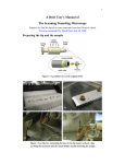
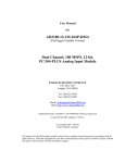
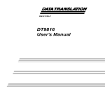
UM1025
User manual
Getting started with STM-STUDIO
Introduction
STM-STUDIO is a graphical user interface that allows sampling and visualizing in real time
user's variables while the application is running. It is designed to run on PCs with Microsoft®
Windows operating systems.
This tool works with STM8 microcontrollers through SWIM (single wire interface module)
and with STM32 microcontrollers through JTAG or SWD (Serial wire debug) interface.
Table 1 lists the products and tools concerned by this user manual.
Table 1.
January 2013
Applicable tools
Type
Applicable tools
Software products
STM-STUDIO
Doc ID 18216 Rev 5
1/40
www.st.com
Contents
UM1025
Contents
1
2
Installing STM-STUDIO . . . . . . . . . . . . . . . . . . . . . . . . . . . . . . . . . . . . . . . 4
1.1
JRE installation . . . . . . . . . . . . . . . . . . . . . . . . . . . . . . . . . . . . . . . . . . . . . . 4
1.2
STM-STUDIO installation . . . . . . . . . . . . . . . . . . . . . . . . . . . . . . . . . . . . . . 4
1.3
Hardware support . . . . . . . . . . . . . . . . . . . . . . . . . . . . . . . . . . . . . . . . . . . . 4
Running STM-STUDIO . . . . . . . . . . . . . . . . . . . . . . . . . . . . . . . . . . . . . . . 5
2.1
Overview . . . . . . . . . . . . . . . . . . . . . . . . . . . . . . . . . . . . . . . . . . . . . . . . . . 5
2.2
Creating variables . . . . . . . . . . . . . . . . . . . . . . . . . . . . . . . . . . . . . . . . . . . 5
2.3
2.4
2.5
2.2.1
Adding absolute variables . . . . . . . . . . . . . . . . . . . . . . . . . . . . . . . . . . . . 6
2.2.2
Adding expression variables . . . . . . . . . . . . . . . . . . . . . . . . . . . . . . . . . . 9
2.2.3
Adding statistical variables . . . . . . . . . . . . . . . . . . . . . . . . . . . . . . . . . . . 10
Inspecting variables . . . . . . . . . . . . . . . . . . . . . . . . . . . . . . . . . . . . . . . . . 11
2.3.1
Adding a variable viewer . . . . . . . . . . . . . . . . . . . . . . . . . . . . . . . . . . . . 11
2.3.2
Customizing variable viewers . . . . . . . . . . . . . . . . . . . . . . . . . . . . . . . . 12
2.3.3
Adding variables to a variable viewer . . . . . . . . . . . . . . . . . . . . . . . . . . . 14
2.3.4
Synchronizing viewers . . . . . . . . . . . . . . . . . . . . . . . . . . . . . . . . . . . . . . 15
2.3.5
Hiding viewers . . . . . . . . . . . . . . . . . . . . . . . . . . . . . . . . . . . . . . . . . . . . 15
Using the Point Viewer . . . . . . . . . . . . . . . . . . . . . . . . . . . . . . . . . . . . . . . 15
2.4.1
Customizing Point Viewer . . . . . . . . . . . . . . . . . . . . . . . . . . . . . . . . . . . 16
2.4.2
Adding a new point . . . . . . . . . . . . . . . . . . . . . . . . . . . . . . . . . . . . . . . . 17
2.4.3
Customizing a point . . . . . . . . . . . . . . . . . . . . . . . . . . . . . . . . . . . . . . . . 18
Configuring the acquisition settings . . . . . . . . . . . . . . . . . . . . . . . . . . . . . 19
2.5.1
Replay from file mode . . . . . . . . . . . . . . . . . . . . . . . . . . . . . . . . . . . . . . 19
2.5.2
Get data from target mode . . . . . . . . . . . . . . . . . . . . . . . . . . . . . . . . . . . 20
2.5.3
Trigger configuration . . . . . . . . . . . . . . . . . . . . . . . . . . . . . . . . . . . . . . . 22
2.6
Project and configurations . . . . . . . . . . . . . . . . . . . . . . . . . . . . . . . . . . . . 24
2.7
Running a visualization session . . . . . . . . . . . . . . . . . . . . . . . . . . . . . . . . 27
2.7.1
Starting a session . . . . . . . . . . . . . . . . . . . . . . . . . . . . . . . . . . . . . . . . . 27
2.7.2
Variable visualization . . . . . . . . . . . . . . . . . . . . . . . . . . . . . . . . . . . . . . . 28
2.7.3
Writing variables on the fly . . . . . . . . . . . . . . . . . . . . . . . . . . . . . . . . . . . 30
2.7.4
Post-visualization analysis . . . . . . . . . . . . . . . . . . . . . . . . . . . . . . . . . . . 33
Appendix A Syntax for expression variables. . . . . . . . . . . . . . . . . . . . . . . . . . . . 35
Revision history . . . . . . . . . . . . . . . . . . . . . . . . . . . . . . . . . . . . . . . . . . . . . . . . . . . . 37
2/39
Doc ID 18216 Rev 5
UM1025
List of figures
List of figures
Figure 1.
Figure 2.
Figure 3.
Figure 4.
Figure 5.
Figure 6.
Figure 7.
Figure 8.
Figure 9.
Figure 10.
Figure 11.
Figure 12.
Figure 13.
Figure 14.
Figure 15.
Figure 16.
Figure 17.
Figure 18.
Figure 19.
Figure 20.
Figure 21.
Figure 22.
Figure 23.
Figure 24.
Figure 25.
Figure 26.
Figure 27.
Figure 28.
Figure 29.
Figure 30.
Figure 31.
Figure 32.
Figure 33.
Figure 34.
Java Platform . . . . . . . . . . . . . . . . . . . . . . . . . . . . . . . . . . . . . . . . . . . . . . . . . . . . . . . . . . . . 4
STM-STUDIO initial screen . . . . . . . . . . . . . . . . . . . . . . . . . . . . . . . . . . . . . . . . . . . . . . . . . 5
Adding absolute variable directly from table . . . . . . . . . . . . . . . . . . . . . . . . . . . . . . . . . . . . . 6
Importing absolute variables . . . . . . . . . . . . . . . . . . . . . . . . . . . . . . . . . . . . . . . . . . . . . . . . . 7
Direct acquisition mode . . . . . . . . . . . . . . . . . . . . . . . . . . . . . . . . . . . . . . . . . . . . . . . . . . . . 8
Snapshot acquisition mode. . . . . . . . . . . . . . . . . . . . . . . . . . . . . . . . . . . . . . . . . . . . . . . . . . 8
Contextual menu to add expression variable . . . . . . . . . . . . . . . . . . . . . . . . . . . . . . . . . . . . 9
Adding statistical variables . . . . . . . . . . . . . . . . . . . . . . . . . . . . . . . . . . . . . . . . . . . . . . . . . 10
Creating a variable viewer . . . . . . . . . . . . . . . . . . . . . . . . . . . . . . . . . . . . . . . . . . . . . . . . . 11
Customizing variable viewers . . . . . . . . . . . . . . . . . . . . . . . . . . . . . . . . . . . . . . . . . . . . . . . 12
Viewers settings . . . . . . . . . . . . . . . . . . . . . . . . . . . . . . . . . . . . . . . . . . . . . . . . . . . . . . . . . 13
Adding variables to a variable viewer . . . . . . . . . . . . . . . . . . . . . . . . . . . . . . . . . . . . . . . . . 14
Synchronizing viewers . . . . . . . . . . . . . . . . . . . . . . . . . . . . . . . . . . . . . . . . . . . . . . . . . . . . 15
Hiding viewers . . . . . . . . . . . . . . . . . . . . . . . . . . . . . . . . . . . . . . . . . . . . . . . . . . . . . . . . . . 15
Point Viewer . . . . . . . . . . . . . . . . . . . . . . . . . . . . . . . . . . . . . . . . . . . . . . . . . . . . . . . . . . . . 16
Point settings . . . . . . . . . . . . . . . . . . . . . . . . . . . . . . . . . . . . . . . . . . . . . . . . . . . . . . . . . . . 16
Adding a point . . . . . . . . . . . . . . . . . . . . . . . . . . . . . . . . . . . . . . . . . . . . . . . . . . . . . . . . . . . 17
Customizing point settings . . . . . . . . . . . . . . . . . . . . . . . . . . . . . . . . . . . . . . . . . . . . . . . . . 18
Acquisition settings dialog box . . . . . . . . . . . . . . . . . . . . . . . . . . . . . . . . . . . . . . . . . . . . . . 19
Trigger parameters . . . . . . . . . . . . . . . . . . . . . . . . . . . . . . . . . . . . . . . . . . . . . . . . . . . . . . . 22
Workspace panel . . . . . . . . . . . . . . . . . . . . . . . . . . . . . . . . . . . . . . . . . . . . . . . . . . . . . . . . 24
Configuration operations in File menu . . . . . . . . . . . . . . . . . . . . . . . . . . . . . . . . . . . . . . . . 25
Selecting hardware and protocol . . . . . . . . . . . . . . . . . . . . . . . . . . . . . . . . . . . . . . . . . . . . 27
Start menu . . . . . . . . . . . . . . . . . . . . . . . . . . . . . . . . . . . . . . . . . . . . . . . . . . . . . . . . . . . . . 27
Variable visualization . . . . . . . . . . . . . . . . . . . . . . . . . . . . . . . . . . . . . . . . . . . . . . . . . . . . . 28
Visualizing different viewers . . . . . . . . . . . . . . . . . . . . . . . . . . . . . . . . . . . . . . . . . . . . . . . . 29
Showing all viewers . . . . . . . . . . . . . . . . . . . . . . . . . . . . . . . . . . . . . . . . . . . . . . . . . . . . . . 29
Adding a write variable . . . . . . . . . . . . . . . . . . . . . . . . . . . . . . . . . . . . . . . . . . . . . . . . . . . . 31
Writing on the fly . . . . . . . . . . . . . . . . . . . . . . . . . . . . . . . . . . . . . . . . . . . . . . . . . . . . . . . . . 31
Editing a value from the Read Value column . . . . . . . . . . . . . . . . . . . . . . . . . . . . . . . . . . . 32
Stop menu . . . . . . . . . . . . . . . . . . . . . . . . . . . . . . . . . . . . . . . . . . . . . . . . . . . . . . . . . . . . . 33
Replaying variable viewer visualization . . . . . . . . . . . . . . . . . . . . . . . . . . . . . . . . . . . . . . . 33
Showing indexes checkbox . . . . . . . . . . . . . . . . . . . . . . . . . . . . . . . . . . . . . . . . . . . . . . . . 34
Showing annotations . . . . . . . . . . . . . . . . . . . . . . . . . . . . . . . . . . . . . . . . . . . . . . . . . . . . . 34
Doc ID 18216 Rev 5
3/39
Installing STM-STUDIO
UM1025
1
Installing STM-STUDIO
1.1
JRE installation
Ensure that the Java Run Time Environment (JRE) is installed on your machine. JRE
version 1.7 or more recent is recommended (JRE 7).
To check the installed JRE version, check that Java bin path is already added to PATH
environment variable, then open a Windows command dialog and enter java -version.
If you have a JRE version older than 1.7, please download the latest JRE version from
http://www.oracle.com/technetwork/java/javase/downloads/index.html.
STM-STUDIO requires the 32-bit version of the JRE to be installed, even on 64-bit versions
of Windows.
Figure 1.
1.2
Java Platform
STM-STUDIO installation
Once the JRE is installed or updated, run STMStudio_setup.exe.
1.3
Hardware support
STM-STUDIO supports ST-LINK hardware with JTAG, SWD and SWIM protocols. STMSTUDIO also supports RLink (in-circuit debugger and programmer from Raisonance which
supports JTAG, ICC and SWIM interfaces), STice advanced emulation system, and STTSLink as additional hardware targets.
4/39
Doc ID 18216 Rev 5
UM1025
Running STM-STUDIO
2
Running STM-STUDIO
2.1
Overview
Run STMStudio.exe through the Desktop icon or the Program Folder shortcut that are
created during the installation setup. The screen shown in Figure 2 appears.
●
The configuration panes display current settings which change according to the type of
display selected.
●
The display area provides a visualization of the various settings currently selected.
Figure 2.
2.2
STM-STUDIO initial screen
Creating variables
It is necessary to create a list of variables to be inspected during the recording session.
STM-STUDIO manages three kinds of variables:
●
Absolute variables that are identified by their physical storage address.
●
Statistical variables that can compute values like min, max, average and standard
deviation of absolute variables.
●
Expression variables that are the result of a mathematical expression evaluation. An
expression is the combination of absolute or statistical variables and mathematical
operators (+,-,*, /…), for example: (Variable1+Variable2)*Variable3. Note that
expression variables are evaluated after statistical variables, thus it is not possible to
compute statistics on expressions.
Doc ID 18216 Rev 5
5/39
Running STM-STUDIO
2.2.1
UM1025
Adding absolute variables
Absolute variables are displayed in the upper pane of the Variables Settings pane. They
can be added in two different ways:
●
Directly from the table using the New contextual menu. The new variable is added with
default parameters. It is the user’s responsibility to define the name, the address, the
size or optionally the color of the variable by editing each of the table fields.
Figure 3.
6/39
Adding absolute variable directly from table
Doc ID 18216 Rev 5
UM1025
Running STM-STUDIO
●
Import variables from an application executable (.elf file) using the File>Import
variables menu. Select the list of variables from the Import variables from
executable menu and click the Import button. The address, size and name
parameters are provided by the executable debug information.
Figure 4.
Importing absolute variables
Doc ID 18216 Rev 5
7/39
Running STM-STUDIO
UM1025
Absolute variables may be acquired in 2 modes:
●
Direct acquisition mode, which is not application intrusive, but does not give an
instantaneous view of the application state
●
Snapshot acquisition mode, which gives an accurate view of the application state, but
which requires application instrumentation. Refer to the Section 2.5: Configuring the
acquisition settings for configuring this mode.
Click on the icon on the left column in order to toggle the acquisition mode of a variable.
8/39
Figure 5.
Direct acquisition mode
Figure 6.
Snapshot acquisition mode
Doc ID 18216 Rev 5
UM1025
2.2.2
Running STM-STUDIO
Adding expression variables
Expression variables are displayed in the middle pane of the Variables settings pane. Use
the New contextual menu to add a new variable. For details on the allowed expression
syntax, please refer to Appendix A: Syntax for expression variables on page 35.
Clicking on the Expression column will open the expression editor window, which will assist
you writing the expression (providing the list of known symbols and functions).
Expressions can use application variables or statistic variables. They can also be constant
(depending on no application or statistic variable). In the general case the result of an
expression cannot be re-used in another expression; only constant expressions can be
reused in other expressions.
Figure 7.
Contextual menu to add expression variable
Doc ID 18216 Rev 5
9/39
Running STM-STUDIO
2.2.3
UM1025
Adding statistical variables
Statistical variables are displayed in the lower pane of the Variables settings pane. Use the
New contextual menu to add a new variable. Then select the absolute variable and the
function to be computed. The scope defines the temporal window of the computing: on all
records acquired since the acquisition start, or only on the last ones (number to be
specified).
Figure 8.
10/39
Adding statistical variables
Doc ID 18216 Rev 5
UM1025
2.3
Running STM-STUDIO
Inspecting variables
Once variables are created, they can be inserted in appropriate windows called “variable
viewers” so that they can be visualized during a session. When creating a new
configuration, one default variable viewer is created but the user can add as many variable
viewers as necessary.
2.3.1
Adding a variable viewer
In the Viewers settings pane, select the General tab and click on the Add Viewer button;
or use the contextual menu within the Viewers settings pane and select the New Var
Viewer item.
A new tab (VarViewer2) is added to the Viewers settings pane and a VarViewer2 window
is displayed in the display area.
Figure 9.
Creating a variable viewer
Display area
Settings pane
Each time a new viewer is created, a new tab is added to the Viewers settings control
pane.
Doc ID 18216 Rev 5
11/39
Running STM-STUDIO
2.3.2
UM1025
Customizing variable viewers
The General tab in the Viewers settings pane contains settings that apply to all variable
viewers.
Figure 10. Customizing variable viewers
●
The format of all viewers: (Curve, Bar Graph or Table) can be changed here in a
single action. This will override the local setting of each viewer, that may be changed
afterwards.
●
Show Indexes: show a slider for all variable viewers to display the time in ms.
●
Add Viewer: create a new variable viewer.
Each viewer supports custom settings that can be modified: select the corresponding tab
and change the settings.
12/39
Doc ID 18216 Rev 5
UM1025
Running STM-STUDIO
Figure 11. Viewers settings
from the Viewers settings pane, you can:
Note:
●
add a New Var Viewer, Rename the viewer, make the viewer Visible or Delete the
selected viewer: use the contextual menu;
●
select the viewer display format: Curve, Bar Graph or Table;
●
select the variable display format: decimal or hexadecimal;
●
remove a variable from the viewer: select the variable in the list and click Delete;
●
clear the list of variables: press the Delete All button;
●
change the vertical axis range of values: set lower Value and upper Value. Each
viewer is associated to a specific range of values. If a variable is outside that range of
values, the variable is not displayed. In this situation, it is useful to modify the vertical
range to make the variable appear.
At least one variable viewer must be defined. Therefore, the Delete Viewer menu is
displayed only if there are at least two variable viewers.
Doc ID 18216 Rev 5
13/39
Running STM-STUDIO
2.3.3
UM1025
Adding variables to a variable viewer
There are two solutions:
●
Drag item from a table of variables and drop it directly either on the variable viewer
display or in the list of variables located in the Viewers settings pane.
●
Use the Send To contextual menu in the Display Variables settings table.
You can use multiple selections in each of the three variable tables to add several variables
at a time in a variable viewer.
Figure 12. Adding variables to a variable viewer
14/39
Doc ID 18216 Rev 5
UM1025
2.3.4
Running STM-STUDIO
Synchronizing viewers
Viewers can be synchronized together: scrolling horizontally in a viewer also affects the
other viewers.
Figure 13. Synchronizing viewers
2.3.5
Hiding viewers
By default, all viewers are visible after creation. It is possible to temporarily hide a viewer (in
order to optimize the displayed area) without loosing its configuration: use the contextual
menu from the corresponding viewer tab.
Figure 14. Hiding viewers
2.4
Using the Point Viewer
By default, a special viewer called Point Viewer is created in addition to the default variable
viewer. The Point Viewer is unique and it does not display variables but points. A point is an
association of two variables resulting in a screen coordinate:
Doc ID 18216 Rev 5
15/39
Running STM-STUDIO
●
A variable on the X axis
●
A variable on the Y axis
UM1025
By default, the Point Viewer is not displayed. To display it, proceed as for the variable
viewers: check the Point Viewer item in the Views menu or the Visible contextual menu in
the Viewers settings pane.
Figure 15. Point Viewer
2.4.1
Customizing Point Viewer
Use the General tab in the Viewers settings pane to modify Point Viewer parameters.
Figure 16. Point settings
For both axes, the user can specify the attempted range of values.
Caution:
If the value of the Variable on X (or on Y) is outside the range of values currently defined for
the X axis (or Y axis), the point does not appear in the Point Viewer area.
The user can also control some display parameters:
●
16/39
Draw Line: when checked, this option is used to draw a curve using all point positions.
By default (Draw Line not checked), the points are displayed as screen points.
Doc ID 18216 Rev 5
UM1025
2.4.2
Running STM-STUDIO
Adding a new point
To create a new point, select the Point Viewer tab in the Viewers settings pane, display
the contextual menu in the List of Points table and click the New menu item. A new point is
added to the list and to the Point Viewer legend.
Figure 17. Adding a point
The new point has a default name and color, no variable on X and Y (as shown by the red
crossed icon visible on Figure 17). It can then be customized.
Doc ID 18216 Rev 5
17/39
Running STM-STUDIO
2.4.3
UM1025
Customizing a point
The point name and color can be modified directly in the list by clicking on the Name field
and on the Color chooser button.
Annotations and variables on X and Y axes can be modified in the Update Point(s) pane
combo boxes. Click on a point in the list to display the settings for that point; any
modification is then registered for the point.
Note:
The Point Viewer can display only variables that are acquired in the same mode.
Select Show Annotations to display the annotations for the specific point.
Point customizing is mandatory for points newly created, but can be done at any time for
existing points either directly in the list for the name and the color or by selecting the point in
the list and modifying the combo boxes or the check box.
Note:
When a point has no variable defined on X (or on Y), a red-crossed icon is added to the list
(see Figure 18). This is the case after creating a new point, but also after deleting a variable
that was referenced by the point. When you select an invalid point, the icon also appears in
the Update Point(s) pane near the combo box that should be filled. You must then update
the point, otherwise it is not displayed during the next visualization session.
Figure 18. Customizing point settings
18/39
Doc ID 18216 Rev 5
UM1025
2.5
Running STM-STUDIO
Configuring the acquisition settings
STM-STUDIO can run in two different modes:
●
Replay from file
●
Get data from target (Direct or Snapshot acquisition, as defined at the variable's level)
Depending on the selected mode, some other parameters may need to be configured. The
acquisition settings are configured through the Option > Acquisition Settings menu.
Figure 19. Acquisition settings dialog box
2.5.1
Replay from file mode
In this mode, data is read from the specified file and no communication with the target is
required. The display is not real time: the Graphical refresh rate defines the time lapse
between records read from the file, independently from their timestamp saved during the
acquisition. Specify the minimum value for the fastest possible replay, or a greater value for
a slower replay.
For a correct behavior, it is recommended to replay a file in the same configuration as the
one used during the acquiring of data into that file.
The mandatory conditions are:
●
The Log raw data parameter must not be changed between the acquisition and the
replay.
●
All absolute variables required by the graphical interface during the replay must be
present in the log file.
●
The Append mode option must be disabled when saving acquired data into the file.
Doc ID 18216 Rev 5
19/39
Running STM-STUDIO
2.5.2
UM1025
Get data from target mode
Variable monitoring may be achieved in two different ways, according to the variable
configuration:
●
Direct acquisition mode - The PC continuously reads data from the connected target.
The maximum record size is six frames of 255 bytes. The acquisition is not intrusive for
the application, except that the SWIM, JTAG or SWD pins must be reserved for the tool
(moreover, on STM8, STM-STUDIO activates the SWIM, which impacts the STM8
behavior after a reset: it remains stalled by the debug module). However, time elapses
between the reading of the first variable of a record and the reading of the last one. This
can sometimes give a wrong image of the application state. For word variables, it can
even lead to unexpected values because MSB and LSB are not read exactly at the
same time.
●
Snapshot acquisition mode - The application must be instrumented so that variables
are sampled on particular application events (user-defined). C source code and project
templates are provided in the “softTrace” subdirectory. Simply add DataAcq.h and
DataAcq.c files into your project, and call the DumpTrace function where you expect to
sample your application state. You may then customize as needed:
–
The maximum number of variables in one record (SNP_TRC_NB_MAX_WORD_
VAR in dataAcq.h): include a safety margin to avoid having to rebuild your
application each time you want to trace one more variable. STM-STUDIO
computes the actual record size when the acquisition session starts. That number
only affects the size of the trace header. STM-STUDIO displays an error message
if you try to trace more variables than the application allows.
–
The size of the trace buffer (SNP_TRC_BUFFER_SIZE): this size does not have
to be a multiple of SNP_TRC_NB_MAX_WORD_VAR, but it must be able to
contain at least two records. A wide buffer is preferred in order to avoid buffer
overflow, all the more if your application calls “DumpTrace” frequently.
For correct synchronization with records acquired in direct mode, a timebase must be
defined, reflecting the exact time period between 2 consecutive calls to DumpTrace:
this is the aim of SNP_TRC_TIMESTAMP_BASE_UNIT and
SNP_TRC_TIMESTAMP_VALUE definition in dataAcq.c.
Some parameters can be adjusted for data acquisition from target:
20/39
●
Graphical refresh rate: number of milliseconds between two graphical refreshes. The
actual refresh rate highly depends on computer configuration, system and execution
environment (the specified value is used to launch a system timer). Note that the
graphical refresh process runs both concurrently and independently from the
acquisition process (the acquisition is in general much faster than the graphical refresh
rate).
●
Under-sample data for graphical display: in this mode, the acquisition process
continues even if the records put at graphical's disposal are still not consumed
(displayed). As a result, when the graphical display is slower than the acquisition, some
acquired records won't be displayed (but will however be logged to the file if the
function is enabled, thus may be displayed later in “replay from file” mode). Conversely,
selecting Display all data will make the acquisition process wait for the previous
records to be consumed by the graphical interface before going further.
●
All variables in acquisition: in this mode all variables that are described in the
Variable Settings control panel are acquired, even if they are not displayed anywhere.
This mode may be useful for optimizing the acquisition (to file) with few variables
displayed during the acquisition time (all variables may be displayed afterwards in
Doc ID 18216 Rev 5
UM1025
Running STM-STUDIO
“replay from file” mode). In Only used variables in acquisition mode, the acquisition
is limited to variables that are displayed in viewers (or used by expressions or statistical
variables that are displayed in viewers). In this mode, the acquisition frames will be
limited to the strict minimum required for display (but of course, the log file won't contain
data for variables not displayed during the acquisition).
●
Log file: name of the file in which data is recorded (when the Log to file option is
selected), or read from (when the Replay from file option is selected).
●
Log to file: save the data read from the target into the specified log file. Note that the
log file may contain more records than displayed during the acquisition session; all
records may be displayed afterwards using the Replay from file option.
●
Log raw data: store raw data as it is read from the target (whole frames, without type
computation).
●
Append mode: when unchecked, the log file is cleared each time the visualization is
started.
●
Log at graphical rate: in general, the acquisition rate is higher than the graphical
refresh rate. Check this control to record at the rate used to refresh the display. This
may be useful when launching relatively long acquisition sessions, in order to avoid
getting too big a file at the end.
●
Log only variations: give the ability to log only records that differ from the previous
one.
●
Append expression and statistic values to log file: when enabled, if any expression
or statistic variable is defined in the project, a post-processing phase takes place each
time the acquisition session is stopped. During this phase, the log file is completed with
values of expression and statistic variables. If disabled, the log file contains only the
data read from the application.
●
Init comm on each start: initialize the communication each time the visualization is
started. If selected, the target communication is also closed at the end of each
acquisition session (allowing another tool to connect without exiting STM-STUDIO). On
STM8, this means that after each “stop” event, the application restarts with SWIM
disabled. If the checkbox is disabled, the SWIM remains active on the STM8 target
after the end of the STM-STUDIO session.
●
Detect STM8 low power modes: select this mode in case of STM8 applications
spending lot of time (several hundreds of milliseconds) in low power mode (HALT,
WFE, WFI) without waking up. This allows the acquisition process not to try to access
resources (RAM data) that are not available in this mode (and avoid communication
errors). In case of applications often switching (several times in 100 milliseconds) in
low power modes, it is preferable to disable this option and increase the number of
allowed consecutive communication errors. As soon as one frame of a record fails, the
whole record is skipped (with such kind of applications, it is recommended to regroup
all variables to be acquired in the minimal address range, thus increasing the
probability to get a full record when the core is awake). Note that it will be all the more
difficult to get records as the core is more rarely awake.
●
Address (in user application) of snapshot trace header: required only if at least one
variable is acquired in snapshot mode. Specify the start address of “g_traceHeader”
variable in the application (address of “g_traceHeader.startMark[0]”). You can find the
address fin the application map file, or obtain it by parsing the application elf file (menu
File>Import variables).
●
Record each N calls to DumpTrace: allows to sub-sample the acquisition in Snapshot
mode. N=1 by default means that a record is stored each time dumpTrace is called.
Doc ID 18216 Rev 5
21/39
Running STM-STUDIO
UM1025
Other positive values allow to reduce the acquisition rate (in order to avoid buffer
overflows for instance) without rebuilding the application.
2.5.3
Trigger configuration
The STM-STUDIO provides the possibility of triggering the acquisition (in Snapshot mode)
or the display (in Direct acquisition mode) on one application event (when getting data from
target). It is also possible to define an end-of-acquisition condition.
Figure 20. Trigger parameters
Trigger acquisition mode
Only one set of trigger conditions (start+stop) is possible at a time, either for variables in
Direct acquisition mode, or for variables in Snapshot acquisition mode. A choice must be
made on which kind of variables the trigger will apply (Direct or Snapshot). In case of mixed
modes acquisition session, the other mode is not affected by the trigger (acquisition
immediately starts, and stops at the end of the recording session).
Start condition
The acquisition behavior depends on the start condition:
●
Manual: The acquisition immediately starts after starting the recording session.
●
Rising edge: the acquisition starts when a sequence of two consecutive records is
found where:
●
Note:
22/39
–
In the first record, the trigger value is strictly below a specified threshold.
–
In the second record, the trigger value is equal or greater than the specified
threshold.
Falling edge: the acquisition starts when a sequence of two consecutive records is
found where:
–
In the first record, the trigger value is strictly greater than a specified threshold.
–
In the second record, the trigger value is equal or lower than the specified
threshold.
Because the tool sampling rate may be much slower than the application's variable variation
rate, it is possible for the tool to miss a condition.
Doc ID 18216 Rev 5
UM1025
Running STM-STUDIO
Stop condition
●
Manual: The acquisition stops on user's request (stop recording session).
●
When buffer full: Available only for trigger defined in Snapshot acquisition. In this
case, the recording stops once the trace buffer allocated in the application is full (no
buffer overwrite).
●
N records after start: Specify the number of records to acquire after the trigger
condition was hit (N=1 will display only the record where the trigger condition was met).
●
Auto restart trigger: Available only when start and stop conditions are different from
“manual”, and pre-triggering is disabled. In this case, the trigger is rearmed after the
stop condition, and the start condition will be evaluated again.
●
Restart timestamp from 0: Available only for trigger defined in snapshot acquisition,
and when “auto restart trigger” is enabled. If enabled, the display is refreshed each time
a new trigger event is hit, and the trigger event record will be assigned with
timestamp=0. If disabled, the timestamp continues to increment between consecutive
trigger events, and several trigger events may be displayed during the same acquisition
session.
●
Ignore trigger when buffer not empty: Available only for trigger defined in Snapshot
acquisition, and when “auto restart trigger” is enabled. If enabled, the trigger is not
immediately rearmed after the stop condition, but only when the trace buffer allocated
in the application is completely empty (acquired records have been displayed). This
allows to avoid having a buffer overflow too soon after the start condition. If disabled,
the trigger is immediately rearmed, which means that the trace recording may start
again (because start condition met again) before the trace buffer of the previous
acquisition is flushed. As a result, a buffer overflow (suspending the recording) may
occur quickly after the trigger event, reducing the acquisition interest.
Pre-triggering
The pre-triggering allows to keep few records before the start condition is met.
●
Note:
N pretrig records: Available only when the start condition is different from “manual”.
The specified value is a maximum, which means that it is possible for the start condition
to be met before all pretrig records have been acquired. In that case, the start condition
is not ignored but less pretrig records are displayed. In snapshot acquisition mode, N
must not exceed the size of the embedded trace buffer (in number of records) minus 2.
In Direct acquisition mode, it must not exceed 200.
Pre-triggering is not compatible with “auto-restart” function. Specifying a value different from
0 pretrig records will disable the “auto restart” function even if selected in the graphical
interface.
Level
The trigger threshold may be defined by either of the following actions:
●
Using a symbol from the application executable file (or linear expression based on
application variable)
●
Specifying the address location and access type of the trigger variable to be used.
Doc ID 18216 Rev 5
23/39
Running STM-STUDIO
2.6
UM1025
Project and configurations
STM-STUDIO enables you to save and reload configurations, so that you do not have to
reconfigure the entire environment each time STM-STUDIO is launched.
Configurations may be grouped into project, allowing to organize them and easily switch
thanks to the workspace panel.
At any time, you can save a configuration, or load or create a new one.
Figure 21. Workspace panel
A configuration includes:
●
the hardware that was in use the last time the configuration was saved
●
the logging settings
●
the list of variables with their settings
●
the list of variable viewers with their settings and the list of variables they are in charge
of displaying
●
the settings for the Point Viewer and the list of points the viewer declares, with their
settings
All configuration operations are located in the File menu.
24/39
Doc ID 18216 Rev 5
UM1025
Running STM-STUDIO
Figure 22. Configuration operations in File menu
●
Open: open a project (tsp) or configuration (tsc) file.
●
New Project: close the current project and open a default project with an empty
configuration.
●
Save Project As: save the current project under a new name (new tsp file).
●
Save: save the current project (tsp file) along with its active configuration (tsc).
●
Recent: load a recently used project or configuration.
The STM-STUDIO caption displays the active configuration. When STM-STUDIO is run, the
configuration is called “New config” by default. After saving or loading the configuration, the
caption title is updated to display the new active configuration.
As soon as a setting is modified, a “*” is added to the active configuration name to signify
that the configuration has been modified and that the user will be asked later to save the
changes.
From the Workspace panel, it is possible to organize configurations into virtual folders (fully
independent from physical directories on disk).
Available actions from folders are:
●
Add new folder: add a new sub-folder to the currently selected one.
●
Add new configuration: add a new (empty) configuration item to the currently
selected folder. This configuration will have to be selected before being modified and
saved.
●
Remove from project: remove the selected folder, all its sub-folders and
configurations. Note that configuration files are not deleted from the disk; only their
references are removed from the project file. It is not possible to remove the project root
folder.
●
Import existing configuration: add a configuration item in the currently selected
folder, making reference to an already existing configuration file (tsc).
●
Import configurations from the recent list: import, in the currently selected folder, all
configurations listed in the recent list. Note that this does not import projects (tsp files).
Doc ID 18216 Rev 5
25/39
Running STM-STUDIO
UM1025
Available actions from inactive (grey LED) configuration are:
●
Remove from project: remove, from the current folder, the reference to this
configuration. The file (tsc), if existing, is not deleted from the disk.
●
Select: set this configuration as active. Equivalent to a double-click. Before acting,
STM-STUDIO will ask for saving the previous active configuration if it has been
modified.
Available actions from active (green LED) configuration are:
1. As long as no file from the disk is associated with this configuration item:
●
Save As: create a configuration (tsc) file on disk and save the configuration settings.
The first time, the filename is used as the name for the configuration item. The
configuration item may be renamed (without affecting the associated filename) with the
“F2” key.
●
Remove from project: remove the configuration item from the folder.
●
Import existing config: associate an existing tsc file on disk to this configuration item.
This will affect the configuration item name, that may be renamed afterwards with the
“F2” key.
2. Once this configuration item has been saved on disk:
●
Save: save all settings in the configuration file on disk (will ask for overwrite
confirmation).
●
Save As: save all settings in another configuration file on disk (create if not existing,
otherwise ask for overwrite confirmation). Note that the previous configuration file on
disk will remain, in its last saved state.
You can use the mouse to move folders and configuration items (drag and drop), and to
change the active configuration (double click).
26/39
Doc ID 18216 Rev 5
UM1025
2.7
Running STM-STUDIO
Running a visualization session
To illustrate a visualization session, a predefined configuration is used with the Point
Viewer and four variable viewers (Slide, Wheel, Keys) and several variables (slide, wheel,
k1, k2 and others).
2.7.1
Starting a session
1.
First use the toolbar combo box to select the hardware and the protocol to be used for
the data acquisition.
Figure 23. Selecting hardware and protocol
2.
Then start the visualization using the Run>Start menu.
Figure 24. Start menu
Doc ID 18216 Rev 5
27/39
Running STM-STUDIO
2.7.2
UM1025
Variable visualization
Figure 25 shows an example screen with a demo running.
Figure 25. Variable visualization
During the visualization, you may:
28/39
●
Visualize another viewer from the Views menu (see Figure 26).
●
Show all viewers using the All visible menu from the viewer settings General tab (see
Figure 27).
●
Change the display of a given viewer select the Keys tab and changing the Display
Mode in the combo box.
●
Add an existing variable to a viewer, for example by dragging the k3 variable from the
table and dropping it over the wheel viewer in the display area.
●
Add new variable viewers and fill them with variables that are already in acquisition, or
based on variables already in acquisition (which is restrictive when in acquisition mode
“Only used variables in acquisition”).
Doc ID 18216 Rev 5
UM1025
Running STM-STUDIO
Figure 26. Visualizing different viewers
Figure 27. Showing all viewers
Some settings can also be changed during the visualization:
●
Variables: color
●
Variable viewers
●
–
Value range
–
Bar graph/curve display
–
Maximizing
Point Viewer
–
Add points
–
Switch between draw mode and point mode
–
Resize axes
Doc ID 18216 Rev 5
29/39
Running STM-STUDIO
UM1025
During visualization, you may not:
●
●
For variables:
–
Create a new variable
–
Change the address of a variable
–
Change the type of a variable
–
Change the name of a variable
For a point:
–
2.7.3
Change variables on X and Y
Writing variables on the fly
During the visualization session, you may write data on the fly. STM-STUDIO provides two
ways of doing this, depending if the variable to be written into is also read (in acquisition) or
not.
For "write only" variables
For "write only" variables, prefer using the Write Variables tab. Proceed as follows:
First create a write variable in the Write Variables tab in the configuration pane. Either one
of three methods can be used:
●
Drag an absolute variable from the Display variable tab to the Write Variables tab.
●
Use the Write Variable tab contextual menus (New or Import) in the same way as for
adding absolute variables (Figure 28).
●
Select
“Import variables from executable” then the “Add variables to the write
variables table” mode.
It is also possible to define as a Write Variable a linear expression based on an absolute
variable (from the application). In this case, the STM-STUDIO reverses the expression
before affecting the absolute variable in the application. The drag-and-drop from Display
Variables tab to Write Variables tab is the only way to add an expression to the Write
variable table.
30/39
Doc ID 18216 Rev 5
UM1025
Running STM-STUDIO
Figure 28. Adding a write variable
Then write a value at the variable address: click on the Write Value field, enter the value,
press Return (see Figure 29). Note that a shorter way is to put the mouse pointer on the
Write Value field, to enter the value and to press Return.
Figure 29. Writing on the fly
The last written value remains displayed, even if the value changes on the application side
(there is no read back from the write table).
Doc ID 18216 Rev 5
31/39
Running STM-STUDIO
UM1025
For "read/write" variables
For "read/write" variables, it may be more simple to use a VarViewer in the Table display
mode. In this mode, the Read Value column may be edited and a write command is sent
when pressing <Enter> or when the edited cell loses the focus. Press <Esc> in order to
cancel the edition without initiating a write command.
Figure 30. Editing a value from the Read Value column
Writing from the VarViewer table works for application variables as well as for linear
expressions based on a single application variables In that case, the STM-STUDIO reverses
the linear expressions before writing to the application variable. It is not possible to write to
expressions that are not linearly-dependent on a single application variable.
32/39
Doc ID 18216 Rev 5
UM1025
2.7.4
Running STM-STUDIO
Post-visualization analysis
To stop the visualization: click on the Run/Stop menu (Figure 31).
Figure 31. Stop menu
●
Horizontal scroll bars are added to enable the user to replay the whole visualization on
both variable viewers (Figure 32) and Point Viewer.
Figure 32. Replaying variable viewer visualization
Scroll bar
Doc ID 18216 Rev 5
33/39
Running STM-STUDIO
●
UM1025
To provide a better Time axis reading on variable viewers, sliders can be added to
popup the time value (select the VarViewers settings General tab and set Show
Indexes: Figure 33).
Figure 33. Showing indexes checkbox
●
For Point Viewer in Point mode, click Show Annotations to display coordinates
(Figure 34).
Figure 34. Showing annotations
34/39
Doc ID 18216 Rev 5
UM1025
Syntax for expression variables
Appendix A
Syntax for expression variables
The parser supports basic mathematical expressions using acquisition variables. Constants
may be expressed in decimal, or hexadecimal with '0x' prefix. Variables are promoted to
doubles before computing. The result of the expression evaluation is also a double that may
be used in any VarViewer.
Supported operators are:
+
Addition
-
Subtraction
*
Multiplication
/
Division
^
Power
%
Integer division
=
Equals
<>
Not equals
&
Bitwise AND
|
Bitwise OR
!
Logical NOT
<
Less than
>
Greater than
<=
Less than or equals
>=
Greater than or equals
>>
Right shift
<<
Left shift
In addition to the basic operators, the parser supports few mathematical functions:
SQR
Square function
SIN
Sinus of an angle expressed in radians
COS
Cosinus of an angle expressed in radians
TAN
Tangent of an angle expressed in radians
ATAN
ArcTangent
SINH
Sinus Hyperbolic
COSH
Cosinus Hyperbolic
COTAN
Cotangent
EXP
Exponent
Doc ID 18216 Rev 5
35/39
Syntax for expression variables
36/39
UM1025
LN
Natural log
LOG
10 based log
SQRT
Square root
ABS
Absolute value
SIGN
SIGN(X) returns -1 if X<0; +1 if X>0, 0 if X=0.
TRUNC
Discards the fractional part of a number.
e.g. TRUNC(-3.2) is -3, TRUNC(3.2) is 3.
CEIL
CEIL(-3.2) = -3, CEIL(3.2) = 4.
FLOOR
FLOOR(-3.2) = -4, FLOOR(3.2) = 3.
RANDOM(X)
Generates a random floating point number such that 0 <= Result <
X. If X is negative, then result is X < Result <= 0.
RND
RND(X) generates a random INTEGER number such that 0 <=
Result < int(X). If X is negative, then result is int(X) < Result <= 0.
INTPOW
The INTPOW function raises Base to an integral power.
INTPOW(2, 3) = 8. Note that result of INTPOW(2, 3.4) = 8 as well.
POW
The Power function raises Base to any power. For fractional
exponents or exponents greater than MaxInt, Base must be greater
than 0.
LOGN
The LogN function returns the log base N of X.
Example LOGN(10, 100) = 2.
MIN
MIN(2, 3) is 2.
MAX
MAX(2, 3) is 3.
MOD
MOD(x,y) function implements the Java % (modulus) operator.
IF
The IF(b, case1, case2) function provides branching capability.
If b is not 0, then it returns case1, else it returns case2.
If b==0 then case1 will not be evaluated, and vice versa.
Doc ID 18216 Rev 5
UM1025
Revision history
Revision history
Table 2.
Document revision history
Date
Revision
12-Nov-2010
1
Initial release.
2
Updated:
– All screenshots
– Section 1.1: JRE installation
– Section 2.1: Overview
– Section 2.2: Creating variables
– Section 2.3: Inspecting variables
– Section 2.4: Using the Point Viewer
– Section 2.6: Project and configurations
– Section 2.7: Running a visualization session
Added:
– Section 2.5: Configuring the acquisition settings
3
Updated:
– Screenshots updated
– Section : Introduction
– Section 2.2: Creating variables
– Section 2.3: Inspecting variables
– Section 2.4: Using the Point Viewer
– Section 2.5: Configuring the acquisition settings
– Section 2.6: Project and configurations
– Section 2.7: Running a visualization session
Added:
– Appendix A: Syntax for expression variables
– Document reformatted as per new die description template
18-May-2011
12-Mar-2012
Changes
Doc ID 18216 Rev 5
37/39
Revision history
UM1025
Table 2.
Document revision history
Date
11-Jun-2012
15-Jan-2013
38/39
Revision
Changes
4
Updated:
– Section 1.1: JRE installation
– Section 2.2.2: Adding expression variables
– Section 2.3: Inspecting variables
– Section 2.5: Configuring the acquisition settings
– Section 2.7.3: Writing variables on the fly
– Figure 3: Adding absolute variable directly from table
– Figure 4: Importing absolute variables
– Figure 8: Adding statistical variables
– Figure 19: Acquisition settings dialog box
Added:
– Section 2.5.3: Trigger configuration
– Figure 5: Direct acquisition mode
– Figure 6: Snapshot acquisition mode
– Figure 20: Trigger parameters.
5
Updated:
– Section 1.1: JRE installation
– Section 1.3: Hardware support
– Section 2.2.2: Adding expression variables
– Section 2.3.3: Adding variables to a variable viewer
– Section 2.3.4: Synchronizing viewers
– Section 2.5.2: Get data from target mode
– Section 2.7.3: Writing variables on the fly
– All the figures.
Doc ID 18216 Rev 5
UM1025
Please Read Carefully:
Information in this document is provided solely in connection with ST products. STMicroelectronics NV and its subsidiaries (“ST”) reserve the
right to make changes, corrections, modifications or improvements, to this document, and the products and services described herein at any
time, without notice.
All ST products are sold pursuant to ST’s terms and conditions of sale.
Purchasers are solely responsible for the choice, selection and use of the ST products and services described herein, and ST assumes no
liability whatsoever relating to the choice, selection or use of the ST products and services described herein.
No license, express or implied, by estoppel or otherwise, to any intellectual property rights is granted under this document. If any part of this
document refers to any third party products or services it shall not be deemed a license grant by ST for the use of such third party products
or services, or any intellectual property contained therein or considered as a warranty covering the use in any manner whatsoever of such
third party products or services or any intellectual property contained therein.
UNLESS OTHERWISE SET FORTH IN ST’S TERMS AND CONDITIONS OF SALE ST DISCLAIMS ANY EXPRESS OR IMPLIED
WARRANTY WITH RESPECT TO THE USE AND/OR SALE OF ST PRODUCTS INCLUDING WITHOUT LIMITATION IMPLIED
WARRANTIES OF MERCHANTABILITY, FITNESS FOR A PARTICULAR PURPOSE (AND THEIR EQUIVALENTS UNDER THE LAWS
OF ANY JURISDICTION), OR INFRINGEMENT OF ANY PATENT, COPYRIGHT OR OTHER INTELLECTUAL PROPERTY RIGHT.
UNLESS EXPRESSLY APPROVED IN WRITING BY TWO AUTHORIZED ST REPRESENTATIVES, ST PRODUCTS ARE NOT
RECOMMENDED, AUTHORIZED OR WARRANTED FOR USE IN MILITARY, AIR CRAFT, SPACE, LIFE SAVING, OR LIFE SUSTAINING
APPLICATIONS, NOR IN PRODUCTS OR SYSTEMS WHERE FAILURE OR MALFUNCTION MAY RESULT IN PERSONAL INJURY,
DEATH, OR SEVERE PROPERTY OR ENVIRONMENTAL DAMAGE. ST PRODUCTS WHICH ARE NOT SPECIFIED AS "AUTOMOTIVE
GRADE" MAY ONLY BE USED IN AUTOMOTIVE APPLICATIONS AT USER’S OWN RISK.
Resale of ST products with provisions different from the statements and/or technical features set forth in this document shall immediately void
any warranty granted by ST for the ST product or service described herein and shall not create or extend in any manner whatsoever, any
liability of ST.
ST and the ST logo are trademarks or registered trademarks of ST in various countries.
Information in this document supersedes and replaces all information previously supplied.
The ST logo is a registered trademark of STMicroelectronics. All other names are the property of their respective owners.
© 2013 STMicroelectronics - All rights reserved
STMicroelectronics group of companies
Australia - Belgium - Brazil - Canada - China - Czech Republic - Finland - France - Germany - Hong Kong - India - Israel - Italy - Japan Malaysia - Malta - Morocco - Philippines - Singapore - Spain - Sweden - Switzerland - United Kingdom - United States of America
www.st.com
Doc ID 18216 Rev 5
39/39