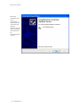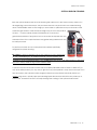
1
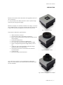
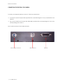
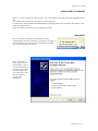
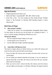
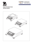
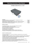
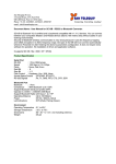
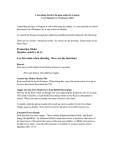
Electra
user manual
may 2006
Copyright 2006 DTA s.r.l.
All rights reserved. The reproduction of any part of this manual is allowed only with the written authorization
by DTA s.r.l..
The contents of this manual may be subject to changes without any warning.
DTA are not responsible for errors that may occur in this manual.
Revision 1.5.1 dated 19/05/2006
Electra user manual
CONTENTS
introduction …… 3
personal computer minimum requirements …… 4
personal computer recommended requirements …… 4
scheme of the installation procedure …… 5
connecting the electra ccd camera …… 6
installation of the drivers …… 7
detail of the electra’s panel connectors …… 11
power supply connector …… 11
user port …… 11
optical window cleaning …… 13
specifications …… 14
backfocus …… 14
index …… 15
©2006 dta s.r.l. p. 1
Electra user manual
p. 2 ©2006 dta s.r.l.
Electra user manual
INTRODUCTION
Electra CCD camera series represent the upgraded version of
all our cameras.
It is very versatile, with USB connection, able to perform high
sensitivity and very good images.
Electra is thought as a modular camera: in the Fig. 1 it is shown
the standard version, in Fig. 2 the camera with the shutter and
in Fig. 3 with shutter and adapter for a chosen mount lens.
Fig. 1: Electra standard
These are the attractive specifications:
•
•
•
•
•
•
•
•
•
•
•
USB connection to the PC.
Powered by a 13.8 V (for battery operation)
Back- and front-illuminated sensors (by Kodak and e2v
technologies).
Full-Frame architecture.
Fast 16 bit A/D Converter at variable gain.
Slow 16 bit A/D Converter for high dynamic range.
Deep cooling with big double stage Peltier (> 50 °C
∆T)
Large fan, with programmable rotational running
(optimised with your application)
Advanced user port for automation and camera
synchronization
Compact size.
Reduced weight and dimensions.
Fig. 2: Electra with shutter
You can fit your system to your requirements adding the
230/115 V Power Supply, the electromechanical shutter and
the lens adapter.
Fig. 3: Electra with shutter and adapter
©2006 dta s.r.l. p. 3
Electra user manual
PERSONAL COMPUTER MINIMUM REQUIREMENTS
•
CPU Pentium IV 1 GHz .
•
256 Mb of RAM.
•
Microsoft Windows 98, ME, 2000, XP or LINUX (we tested the SuSE LINUX 9.0 version).
•
USB 1.1/2.0 compliant.
PERSONAL COMPUTER RECOMMENDED REQUIREMENTS
• CPU Pentium IV 2 GHz or higher.
• 512 Mb RAM.
• Colour monitor 19”.
• Microsoft Windows XP Pro.
• USB 1.1/2.0 compliant.
• Wheel mouse
p. 4 ©2006 dta s.r.l.
Electra user manual
SCHEME OF THE INSTALLATION PROCEDURE:
When you use the camera for the first time,
you must install the ViSTA software.
Insert the ViSTA 3 CD-ROM, provided with the
camera, into the CD-ROM reader, wait a few
seconds so as to allow the PC to load the
"QUICK INSTALL" menu.
Let click on ViSTA 3 and QUICK INSTALL will
start and take you through the process of
installing the software.
The default settings will install the full software
package and all options.
You may be asked to reboot the PC if certain
files in use by Windows needs to be updated.
©2006 dta s.r.l. p. 5
Electra user manual
CONNECTING THE ELECTRA CCD CAMERA
To install your hardware platform on the PC, follow the steps below:
⇒ Connect the power supply cable (supplied with a standard length of 2,5 m) to the Electra CCD
camera
⇒ Turn on the camera and connect the USB cable (supplied with a standard length of 5 m) to the
corresponding port of the PC
Now, install the drivers for the USB connession.
Power supply connector
p. 6 ©2006 dta s.r.l.
USB connector
User Port
Electra user manual
INSTALLATION OF THE DRIVERS:
When you use the camera for the first time, you will be asked to specify where the available drivers
are.
Let’s analyse the sequence of operations to be carried out.
It will be shown the example with WINDOWS XP Operating System. The operation are similar for the
other Operating Systems.
Follow the steps on the basis of your Operative System.
WINDOWS XP
Once you have connected the camera to the PC
following the instructions reported on the previous page, a
window (like the one shown below) will appear, noticing
you a new hardware was found.
Then, it appears a
window like the one
shown below, where
you’ll be requested to
connect for Windows
update. Select: “No,
not at this time” and
click on "Next" to
continue the
installation.
©2006 dta s.r.l. p. 7
Electra user manual
Select the option
"Install from a list or
specific location
(Advanced)”
(recommended
choice). Then click
on "Next" to
continue the
installation.
Check the
functions
selected in the
window below
(in this case, E:\
indicates the
CD-ROM drive)
and click on
next to
continue.
p. 8 ©2006 dta s.r.l.
Electra user manual
Select the folder that contains drivers for USB
hardware according to the Operative
System:
• Windows 98/Me2000/XP: select Windows
• Windows XP Professional x64: select XPx64
(as in the image below)
Then, click on OK and wait while the wizard
installs the software (just few seconds).
©2006 dta s.r.l. p. 9
Electra user manual
When the
installation has
been
completed, a
window like the
one below will
appear.
Click on finish to
close the wizard
and restart the
PC
(recommended
choice).
p. 10 ©2006 dta s.r.l.
Electra user manual
DETAIL OF THE ELECTRA’S PANEL CONNECTORS
Here following the details of the Electra connectors:
POWER SUPPLY CONNECTOR
POWER SHUTTER
POSITIVE +
NEGATIVE -
Front view
By means of this connector 12V 5A power is carried to the ELECTRA.
USER PORT
WARNING: All the signals present on this port are compliant to 3.3V TTL standard and NOT to 5V TTL
standard. To violate this standard would involve serious damages to the camera. If
you have the necessity to use a 5V signal, we suggest you to connect in series a 100 Ω
resistance.
1
4
7
10
13
16
19
22
25
+3.3V
PA2
PA5
PB0
PB3
PB6
AD1
SHUT INPUT
SHUTTER
2
5
8
11
14
17
20
23
26
PA0
PA3
PA6
PB1
PB4
PB7
AD2
TRIG INPUT
GND
3
6
9
12
15
18
21
24
-
PA1
PA4
PA7
PB2
PB5
AD0
AD3
TRIG OUT
-
©2006 dta s.r.l. p. 11
Electra user manual
•
•
•
•
•
•
3.3 V: digital supply
PA[0:7]: bidirectional parallel port reserved for user.
PB[0:7] : bidirectional parallel port reserved for user
AD[1:3]: 12 bit a/d Converter input
SHUT INPUT: shutter input
TRIG INPUT: Trigger input.
When we enable the TRIGGER mode, it is necessary to provide the signal for starting the
camera acquisition. In fact, when we run the function: “DC_GetCCD”, the camera, after
the Clear CCD operation, wait for the hardware signal to start the acquisition, that is the
TRIG INPUT signal.
This signal is RISING EDGE SENSITIVE
Once the signal is provided, after just 1-2 ns, it opens the shutter, start the acquisition of the
image (the acquisition time is prefixed by the user), then, after the hysteresis time for the
shutter closure, there is the image downloading.
• SHUTTER: TTL signal output, it is high active for all the time of shutter opening. It can be used
for manage an external shutter.
• GND: ground.
p. 12 ©2006 dta s.r.l.
Electra user manual
OPTICAL WINDOW CLEANING
Both the optical window and the CCD cleaning are carried out in the clean room by means of a
30-magnifying power microscope. This procedure removes any dust which can otherwise bring
about unmistakable marks on the image you have taken. In particular such spots increase as the
focal ratio gets wider. In other words an image may not show any mark at
f/5.6 but
it can be clearly noted at f/32 because of an obvious
geometrical problem of projection. Due to the shutter or elapsed time, the
external surface of the optical window may gather dirty particles that may
be easily removed.
To perform such task we use a compressed air cylinder specifically
designed for optical cleaning.
Be careful !!! There are similar products that, instead of using compressed
air, use a liquefiable gas : at ambient pressure it quickly gassifies, thus
“triggering” an air-compressed-effect. You do not absolutely have to use these products : they may
give rise to heavy marks or rings on the windows itself.
A product we can recommend is DUST-OFF provided by EDMUND-OPTICS. Thanks to DUST-OFF (or
any other similar product) it is very easy to get rid of any microparticles : keep the shutter open for a
few seconds (by the camera control program) and spray some air blast. We kindly advise you
against using cloths, optical paper and cleaning liquids because the dirt will be only mixed up or,
even worse, increased. The risk is to finally damage the coating of the optical window itself !
©2006 dta s.r.l. p. 13
Electra user manual
SPECIFICATIONS
SHUTTER:
Electromechanical. Exposure time: from 0.01 s to 9999 s
A/D CONVERTER:
Selectable: 12, 14, 16 bit
SETTABLE GAINS:
64
READ OUT SPEED:
250 kpixel/s
INTERFACE:
USB 1.1/2.0
COOLING:
Double stage PELTIER (> 50°C ∆T below ambient)
CCD TEMPERATURE CONTROL:
± 0.1 °C
FILTER WHEEL:
External
BINNING:
From 1 x 1 to 8 x 8 or arbitrary
POWER SUPPLY (optional):
230V 50Hz.
MAX ABSORPTION:
75 W
WEIGHT:
1400 g
DIMENSIONS:
160x130x100 mm
BACKFOCUS:
MINIMUM EXPOSURE
TIME (ms)
SHUTTER
CCD CAMERA MODEL
BACKFOCUS (mm)
No shutter
All models
6
EV-25
EL-260E, EL-400E/LE/ME, EL1400E/ME, EL-1600E/LE/ME, EL3200E/ME, EL-4710F/B, EL-7700F/B
29
5
EV-35
EL-4200E, EL-6000E/LE, EL-3011F/B,
EL-4210F/B
29
20
EV-45
EL-1000E
31.5
50
p. 14 ©2006 dta s.r.l.
Electra user manual
INDEX
b
backfocus …… 14
c
connecting the electra ccd camera …… 6
d
detail of the electra's panel connectors …… 11
i
introduction …… 3
installation of the drivers …… 7
o
optical window cleaning …… 13
p
personal computer minimum requirements …… 4
personal computer recommended requirements …… 4
power supply connector …… 11
s
scheme of the installation procedure …… 5
specifications …… 14
u
user port …… 11
©2006 dta s.r.l. p. 15
Electra user manual
dta s.r.l. viale campania 23, 56021cascina (pisa) - italy, web site: www.dta.it , e-mail: [email protected]
p. 16 ©2006