1
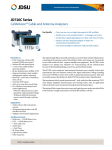
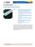
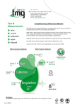
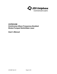
COMMUNICATIONS TEST & MEASUREMENT SOLUTIONS
SmartClass™ E1/Datacom
E1 Service Installation and Maintenance Tester
Key Features
• Performs E1/Datacom service installation and maintenance
in easy-to-use, lightweight, and rugged form-factor
• Significantly reduces field technician training with Smart
AutoConfiguration (AutoConfig) feature
• Works with PC software—download results for report
preparation
• Provides additional E1 and Datacom testing with available
software options
• Includes Event Log and Histogram for troubleshooting
• Capable of bidirectional monitoring and troubleshooting
via dual E1 ports
Applications
E1
• Provides terminate, monitor, bridge,
and local loopback modes
• Provides G.703 — 2 Mb/s testing
• Conducts 2 M (Bulk), n x 64 kb/s BERT
• Measures performance G.821, G.826,
and M.2100
• Provides audio monitor (VF drop)
• Provides transmit frequency offset
• Performs VF level and frequency
measurements, VF tone insert
• Measures E1 signal level measurement
• Provides ABCD/Sa monitoring
• Provides round-trip delay
• Offers alarms (defects) and errors
(anomalies) insertion
• Pulse shape (optional)
• MFC-R2 (optional)
• Offers color graphical user interface (GUI) available in
multiple languages
• Supports G.703 Codirectional, Contradirectional, and
Centralized interface testing
The JDSU SmartClass E1 is a handheld field tester for the installation and
commissioning of E1 and Datacom service that offers multiple test modes
for E1 and Datacom signal analysis. An economical and easy-to-use point
solution, the SmartClass E1 has a Smart AutoConfiguration (AutoConfig)
feature and large, easy-to-read color display that make the lightweight,
rugged, battery-operated tester ideal for both service provider and contractor field technicians. It also meets the needs of mobile operators in the
construction of E1 backhaul infrastructure.
Datacom
• Offers DTE emulate, DCE emulate,
and monitor mode
• Interfaces with X.21, V.24 (RS-232),
V.35, V.36 (RS-449), and EIA-530
• Provides round-trip delay
• Frame Relay (optional)
• Conducts G.703 Codirectional,
Contradirectional, and Centralized
interface testing
Others
• Provides VT-100 terminal emulation
(optional)
• Offers remote control (optional)
WEBSITE : www.jdsu.com/test
Pulse shape for extra E1 testing capability
SMARTCLASS E1/DATACOM
2
Specifications
E1 Circuit Testing
Errors (Anomalies) Insert
Datacom Circuit Testing
Interfaces
Dual RJ48 ports (port 1 Rx/Tx, port 2 Rx only)
120 balanced RJ48 (by default)
120 balanced CF, 75 unbalanced BNC (via adapter cable)
Line Code
AMI, HDB3
Tx Timing
Internal
Recovered
External (via adapter cable on Port 2)
Tx Frequency Offset
±100 ppm in 1 ppm intervals
Framing
Unframed, PCM31, PCM31C, PCM30, PCM30C
Test Mode
Terminate, monitor, bridge, local loopback
2M (Bulk), n x 64 kbps BERT
AutoConfig for framing and test pattern
LED Indicators
SYNC, ALARM, ERROR, DATA, LPBK, BATT
2M code
Single
2M FAS
Single, 2, 3, 4
2M MFAS
Single, 2
2M CRC
Single
BERT pattern slip
Single
E-Bit/REBE
Single, Continuous
Bit (TSE)
Single-rate 1e-2, 1e-3, 1e-4, 1e-5, 1e-6, 1e-7,
Multiple 1 to 50
Interfaces
X.21,V.24 (RS232),V.35,V.36 (RS449), and EIA-530
via adapter cable
G.703 Codirectional, Contradirectional, and Centralized
Interface testing via adapter cable
Data Rates (Emulate and Monitor)
X.21
Sync 50 bps to 10 Mbps
V.24 (RS-232)
Async 50 bps to 128 kbps
V.24 (RS-232)
Sync 50 bps to 128 kbps
V.35
Sync 50 bps to 2048 kbps
V.36 (RS-449)
Sync 50 bps to 10 Mbps
EIA-530
Sync 50 bps to 10 Mbps
BERT Patterns
All Ones, All Zeros,
1:1, 1:3 (1 in 4), 1:4 (1 in 5), 1:7 (1 in 8), 3:1, 7:1,
63 (26-1), 511 (29-1), 2047 (211-1), 2047R, 2047R INV, 215-1
(ANSI, ITU), 220-1 (ANSI, ITU), 223-1 (ANSI, ITU), QRSS, QBF, Delay
User Bit Pattern (3 to 32 bits)
User Byte Pattern (1 to 64 bytes)
Transmit Clock Sources
Internal ±3 ppm, 1 ppm per year aging
Interface
Signaling Lead Control
Emulate DTE
RTS, DTR, LL, RL
Emulate DCE
CTS, DSR, DCD,TMA
Monitor
Self Loop
Internal
External Cable Test
Result Categories
Summary, Clock, BERT, Data, Control Signal, G.821,Time
Performance Monitoring
G.821, G.826, and M.2100
ABCD/Sa monitoring
Round-trip delay
Test Patterns
All ones, All zeros
1:1, 1:3 (1 in 4), 1:4 (1 in 5), 1:7 (1 in 8),
63 (26-1), 511 (29-1), 2047 (211-1), ITU INV215-1, ITU215-1, ITU
INV220-1, ITU220-1, ITU INV223-1, ITU223-1, QBF, QRSS, LIVE
User bit pattern (3 to 32 bits)
User byte pattern (1 to 64 bytes)
Key Results
Loss alarms, LOS seconds
code error count, code error rate, timing slips, frame slips,
LOF alarms, LOF seconds, AIS alarms, AIS seconds, RDI alarms
RDI seconds, MF AIS alarms, MF AIS seconds, MF RDI alarms,
MF RDI seconds
FAS bit error count, FAS bit error rate, FAS word error count,
MFAS word error count, MFAS word error rate, CRC error Count,
CRC error rate, CRC sync loss count
FAS sync loss count, MFAS sync loss count, remote end block
error (E-Bit/REBE), NFAS word, MFAS word, NMFAS word
Si bit, A bit, Sa-bit sequence (Sa4–Sa8)
TSE/bit error count,TSE/bit error rate, block error count
pattern slips, pattern slip seconds
pattern synchronization loss count, pattern synchronization
loss seconds, round trip delay (µs), elapsed time, time,
date/time-slot Rx byte, time-slot signaling data
Alarms (Defects) Insertion
LOS
Loss of frame (LOF)
AIS
RDI / FAS Dist
MF AIS
MF RDI / MFAS dist
Continuous
Continuous
VF Tests
VF level and frequency measurement
VF tone insert
404, 1004, 2713, 2804 Hz,
–13.0, –3.0, 0.0, 3.0 dBm
VF drop to built-in speaker
Pulse Shape (optional)
Parameter Specification
Results
G.703 mask
Pulse width resolution
Rise time resolution
Fall time resolution
Undershoot resolution
Overshoot resolution
Signal level in [V] base-peak
Pulse shape graph
Pass/Fail
2.75 ns
1 ns
1 ns
1% of nominal level
1% of nominal level
MFC-R2 (optional)
Test Mode
Country selection
Monitor, Simulate (Call in or out)
ITU-T, Brazil, Mexico, and India
SMARTCLASS E1/DATACOM
3
Specifications
Frame Relay (optional)
Interface
Datacom
Test Mode
Terminate and Monitor (UNI-U, UNI-N, NNI)
Link Management Auto-Detect (default setting), ANSI T1.617
Annex D, ITU-T Q.933 Annex A, LMI Rev 1, None
DLCI
0 – 1023
Link Trace
Simple,Verbose,Text, Hex,Text, and Hex
Long Frame
5 – 9999
Load Test
Test of CIR (load)
Off, Fixed, Burst, Ping
CIR Fixed Rate
1 – 10,000 kbit/s
Frame Lengths
5 – 9999
Payload
Sequence, User 1, User 2, Sequence + User
Control Bits
FECN, BECN, DE, C/R
Burst Settings
Tx time, Idle time
Ping
Settings
Source IP Address, Destination IP Address,
Inverse ARP, Ping Length
Encapsulation
NLPID, Ethertype
Result Categories
Frame Relay (DLCI, Link, Ping, LMI, DLCI List,Trace) and Datacom
Other Software Options
VT-100 (optional)
This option enables the instrument to emulate a VT-100
terminal and to connect to network device via instrument
9-pin RS232 interface.
Remote Control (optional)
Lets the user use command lines to control the tester via serial
interface.Command guide is available with the option.
General Specifications
Ordering Information
Languages
English, French, German, Italian, Japanese, Korean, Portuguese,
Russian, Simplified Chinese, and Spanish
Power
4 AA field-replaceable batteries (NiMH or Alkaline)
NiMH battery operating (at 25ºC) under typical conditions
provides up to 5 hours of continuous use for E1 application
and 2 hours of continuous use for Datacom application
Supports sleep mode
AC line operation via external adapter
Charging time (at 25ºC) under typical conditions for empty to
full charge: with unit OFF up to 5 hours; with unit ON up to
7 hours
Permissible Ambient Temperature
Nominal range of use 0 to +50°C
Storage and transport –10 to +60°C
Humidity
Operating humidity 10 to 90%
Physical Specifications
Size (H x W x D)
230 x 120 x 50 mm
Weight, including batteries
<1 kg (2 lb)
Display
320 x 240 color display
CE Marked
Order Number
CSC-E1DC-P1
Description
SmartClass E1 Datacom Package
(No software options included)
CSC-E1DC-P2
SmartClass E1 Datacom Pulse Shape
and Frame Relay Package
(Pulse Shape and Frame Relay
software option included)
CSC-E1DC-P3
SmartClass E1 Datacom Premium Package
(Pulse Shape, MFC-R2, Frame Relay, and
VT-100 software option included)
Accessories included with any package
AC power adapter with plug kit (USA, UK, Australia, Europe)
4 x AA NiMH batteries
CD-ROM (including PC utility, USB driver, and User Guide)
1 x RJ48-to-RJ48 cable
1 x USB cable
Small carrying bag
Optional Accessories
E1 Cables
K1597
RJ48 to CF Y cable (120 Ω balanced)
CB-44995
RJ48 to Dual BNC cable (75 Ω unbalanced)
CB-0045402
2M External Clock Reference cable
Datacom Cables
CB-44391
X.21 10M DTE/DCE Emulate
(Support up to 10 Mb/s)
CB-44346
X.21 Monitor
CB-44385
V.24 DTE/DCE Emulate
CB-44348
V.24 Monitor
CB-44389
V.35 DTE/DCE Emulate
CB-44341
V.35 Monitor
CB-44388
V.36 DTE/DCE Emulate
CB-44347
V.36 Monitor
CB-21118474
68-pin MDR to Bananas
CB-21128081
68-pin MDR to DB15
(CB-2118474 and CB-21128081 for G.703 Codirectional,
Contradirectional, and Centralized interface testing)
Miscellaneous
CC-120101
Large Carrying Bag
AC-009801
Large Strand Hook
SCACARCHARGER
Car Adapter Charging Kit
ML-21107607
Printed User Manual SC E1 (English)
ML-21121114
Printed SC E1 Remote Control
Reference Guide (English)
Software Options
CSC-E1-PS
Pulse Shape
CSC-E1-SIG
MFC-R2
CSC-E1-FR
Frame Relay
CSC-E1-VT100
VT-100
CSC-E1-RC
Remote Control
SMARTCLASS E1/DATACOM
Test & Measurement Regional Sales
NORTH AMERICA
TOLL FREE : 1 866 228 3762
FAX : +1 301 353 9216
LATIN AMERICA
TEL : +55 11 5503 3800
FAX : +55 11 5505 1598
ASIA PACIFIC
TEL : +852 2892 0990
FAX : +852 2892 0770
Product specifications and descriptions in this document subject to change without notice. © 2008 JDS Uniphase Corporation
EMEA
TEL : +49 7121 86 2222
FAX : +49 7121 86 1222
October 2008
www.jdsu.com/test
30149142 005 1008
SMARTCLASSE1.DS.ACC.TM.AE