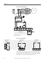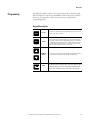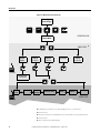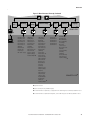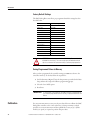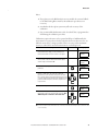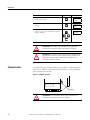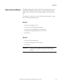
1
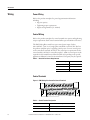
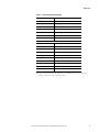
Quick Start
SMC Dialog Plus™ Controller
Bulletin 150
Important User Information
Solid-state equipment has operational characteristics differing from those of electromechanical equipment. Safety
Guidelines for the Application, Installation and Maintenance of Solid State Controls (publication SGI-1.1 available from
your local Rockwell Automation sales office or online at http://www.rockwellautomation.com/literature/) describes some
important differences between solid-state equipment and hard-wired electromechanical devices. Because of this difference,
and also because of the wide variety of uses for solid-state equipment, all persons responsible for applying this equipment
must satisfy themselves that each intended application of this equipment is acceptable.
In no event will Rockwell Automation, Inc. be responsible or liable for indirect or consequential damages resulting from
the use or application of this equipment.
The examples and diagrams in this manual are included solely for illustrative purposes. Because of the many variables and
requirements associated with any particular installation, Rockwell Automation, Inc. cannot assume responsibility or
liability for actual use based on the examples and diagrams.
No patent liability is assumed by Rockwell Automation, Inc. with respect to use of information, circuits, equipment, or
software described in this manual.
Reproduction of the contents of this manual, in whole or in part, without written permission of Rockwell Automation,
Inc., is prohibited.
Throughout this manual, when necessary, we use notes to make you aware of safety considerations.
WARNING: Identifies information about practices or circumstances that can cause an explosion in a hazardous
environment, which may lead to personal injury or death, property damage, or economic loss.
ATTENTION: Identifies information about practices or circumstances that can lead to personal injury or death,
property damage, or economic loss. Attentions help you identify a hazard, avoid a hazard, and recognize the
consequence
SHOCK HAZARD: Labels may be on or inside the equipment, for example, a drive or motor, to alert people that
dangerous voltage may be present.
BURN HAZARD: Labels may be on or inside the equipment, for example, a drive or motor, to alert people that
surfaces may reach dangerous temperatures.
IMPORTANT
Identifies information that is critical for successful application and understanding of the product.
SMC Dialog Plus, Allen-Bradley, Rockwell Software, Rockwell Automation, and TechConnect are trademarks of Rockwell Automation, Inc.
Trademarks not belonging to Rockwell Automation are property of their respective companies.
Quick Start
Introduction
This quick start guide provides you with the basic information required to
start up your SMC Dialog Plus™ controller. Factory default settings and
information regarding installing, programming, and calibrating the
controller are described here.
The information provided in this Quick Start Guide does not replace the User
Manual, which can be ordered or downloaded by visiting www.ab.com/literature.
The Quick Start guide assumes the installer is a qualified person with previous
experience and basic understanding of electrical terminology, configuration
procedures, required equipment, and safety precautions.
For safety of maintenance personnel as well as others who might be exposed to
electrical hazards associated with maintenance activities, follow all local safety
related work practices (e.g., the NFPA 70E, Part II in the United States).
Maintenance personnel must be trained in the safety practices, procedures, and
requirements that pertain to their respective job assignments.
For detailed SMC-Dialog Plus information including setup, programming,
precautions, and application considerations, refer to the following:
Cautions and Warnings
For Documentation
SMC-Dialog Plus User Manual
150-5.3
www.ab.com/literature
For Technical Support
E-mail Support
[email protected]
Telephone Support
440-646-5800, option 2, option 4
or use direct dial code 804
The following cautions and warnings must be observed while installing and using
the SMC Dialog Plus controller.
Rockwell Automation Publication 150-QS002B-EN-P - October 2011
3
Quick Start
General Precautions
ATTENTION: Hazardous voltage is present in the motor circuit even
when the SMC-Dialog Plus controller is off. To avoid shock hazard,
disconnect the main power before working on the controller, motor, and
control devices such as Start-Stop push buttons. Procedures that require
parts of the equipment to be energized during troubleshooting, testing,
etc., must be performed by properly qualified personnel, using appropriate
local safety work practices and precautionary measures.
ATTENTION: Failure of solid-state power switching components can
cause overheating due to a single-phase condition in the motor. To
prevent injury or equipment damage, the use of an isolation contactor or
shunt trip type circuit breaker on the line side of the SMC is
recommended. This device should be capable of interrupting the motor’s
lock rotor current.
ATTENTION: Hazardous voltages that can cause shock, burn, or death
are present on L1, L2, L3,T1, T2, and T3. Disconnect the main power
before servicing the motor controller, motor, or associated wiring.
ATTENTION: The controller contains ESD (electrostatic discharge)
sensitive parts and assemblies. Static control precautions are required
when installing, testing, servicing, or repairing the assembly.
Component damage may result if ESD control procedures are not
followed. If you are not familiar with static control procedures, refer to
applicable ESD protection handbooks.
ATTENTION: An incorrectly applied or installed controller can damage
components or reduce product life. Wiring or application errors, such
as undersizing the motor, incorrect or inadequate AC supply, or
excessive ambient temperatures, may result in malfunction of the
system.
ATTENTION: Only personnel familiar with the controller and
associated machinery should plan or implement the installation,
start-up, and subsequent maintenance of the system. Failure to do this
may result in personal injury and/or equipment damage.
ATTENTION: Disconnect the controller from the motor before
measuring insulation resistance (IR) of the motor windings. Voltages
used for insulation resistance testing can cause silicone-controlled
rectifier (SCR) failure. Do not make any measurements on the controller
with an insulation resistance (IR) or Megger tester.
ATTENTION: The controller can be installed on a system with power
factor correction capacitors (PFCC). The PFCC capacitors must only be
located on the line side of the SMC. Installing PFCC capacitors on the
load side wil result in SCR damage and failure.
ATTENTION: After a short-circuit occurs, device functionality must be
verified.
4
Rockwell Automation Publication 150-QS002B-EN-P - October 2011
Quick Start
Overload
ATTENTION: Overload protection in the SMC Dialog Plus controller is
disabled from the factory. The user must program the desired overload
trip class and motor full load current rating to achieve proper protection
ATTENTION: Overload protection should be properly coordinated with
the motor.
ATTENTION: During slow speed and/or braking operations, current
waveforms exhibit non-sinusoidal characteristics. These non-sinusoidal
characteristics inhibit the controller’s current measurement capability.
To compensate for additional motor heating that may result, the
controller uses motor thermal modeling, which increments motor
thermal usage. This compensation takes place when these options are
in use: Preset Slow Speed, Smart Motor Braking, Accu-Stop, and Slow
Speed with Braking.
Communication
ATTENTION: Only one peripheral device can be connected to the
SCANport. The maximum output current through the SCANport is
100 mA.
Human Interface Module
ATTENTION: The Bulletin 1201 human interface module’s stop push
button is not intended to be used as an emergency stop. Refer to the
applicable standards for emergency stop requirements.
Control Options
Soft Stop
ATTENTION: Soft Stop is not intended to be used as an emergency
stop. Refer to the applicable standards for emergency stop
requirements.
Rockwell Automation Publication 150-QS002B-EN-P - October 2011
5
Quick Start
Pump Control
ATTENTION: Pump stopping is not intended to be used as an
emergency stop. Refer to the applicable standard for emergency stop
requirements.
ATTENTION: Pump stopping may cause motor heating depending on
the mechanical dynamics of the pumping system. Therefore, select the
lowest stopping time setting that will satisfactorily stop the pump.
Preset Slow Speed
ATTENTION: Slow speed running is not intended for continuous
operation due to reduced motor cooling.
SMB™ Smart Motor Braking Option
ATTENTION: SMB Smart Motor Braking is not intended to be used as
an emergency stop. Refer to applicable standards for emergency stop
requirements.
Accu-Stop™ and Slow Speed with Braking
ATTENTION: Accu-Stop and Slow Speed with Braking are not
intended to be used as an emergency stop. Refer to applicable
standards for emergency stop requirements.
Fast Acting Current-limiting Fuses
ATTENTION: The fast acting current-limiting fuses specified in Table
2.C of the user manual may not provide branch circuit protection.
Branch circuit protection in accordance with applicable electrical codes
may require additional fusing (or a circuit breaker) even though fast
acting current-limiting fuses are used.
ATTENTION: Applications requiring extended acceleration times or
high duty cycles may experience nuisance tripping of the coordinated
fast acting current-limiting fuses. This type of fuse has a limited
thermal capacity that is less than that of the SCRs they are designed to
protect. This makes them susceptible to thermal fatigue.
6
Rockwell Automation Publication 150-QS002B-EN-P - October 2011
Quick Start
Protective Modules
ATTENTION: To protect the Smart Motor Controller (SMC) and/or motor
from line voltage surges, protective modules may be placed on the line,
load, or both sides of the SMC. Do not place protective modules on
the load side of the SMC when when using pump or braking control.
ATTENTION: When installing or inspecting the protective module,
make sure that the controller has been disconnected from the power
source. The protective module should be inspected periodically for
damage or discoloration. Replace if necessary.
Note: Protective modules are not designed to protect against lightning
strikes to equipment or distribution lines.
Electromagnetic Compatibility (EMC)
.
ATTENTION: This product has been designed for Class A equipment.
Use of the product in domestic environments may cause radio
interference, in which case, the installer may need to employ additional
mitigation methods.
Fan Power
ATTENTION: The fan jumpers have been factory installed for
110/120V AC input. Refer to Figure 3 of this quick start guide or Figure
3.6 through Figure 3.8 of the user manual for 220/240V AC fan wiring.
Note that 220/240V AC fan wiring is not available for the 650…1000 A
controllers. After wiring for the 97 A and 135 A controllers is complete,
replace control terminal strip cover.
Installation
The open-style design of the SMC Dialog Plus controller requires that it be
installed in an enclosure. The internal temperature of the enclosure must be
kept within 0 …5 °C (32…122 °F).
The controller is convection cooled. It is important to mount the controller in a
position that allows air to flow vertically through the power structure. Allow for a
minimum of six inches (15 cm) of free space around all sides of the controller.
Rockwell Automation Publication 150-QS002B-EN-P - October 2011
7
Quick Start
Wiring
Power Wiring
Refer to the product nameplate for power lug termination information
including:
• Lug wire capacity
• Tightening torque requirements
• Lug kit catalog numbers (97…1000 A)
Control Wiring
Refer to the product nameplate for control terminal wire capacity and tightening
torque requirements. Each control terminal will accept a maximum of two wires.
The SMC Dialog Plus controller accepts control power input of either
100…240V AC, (+10/–15%) single-phase, 50/60 Hz or 24V AC/DC. Refer to
the product nameplate prior to applying control power. Connect control power
to the controller at terminals 11 and 12. The control power requirement for the
control module is 40 VA. For controllers rated 97…1000 A, control power is also
required for the heatsink fans as defined in Table A. Depending on the specific
application, additional control circuit transformer VA capacity may be required.
Table 1 - Heatsink Fan Power Requirements
SMC Rating
Heatsink Fan VA
97…360 A
45
500 A
145
650…1000 A
320
Control Terminals
Figure 1 - SMC Dialog Plus Controller Control Terminals
11
13
12
21
22
15
14
23
24
25
18
17
16
26
27
Table 2 - Control Terminal Designation
Terminal Number
8
Description
11
Control Power Input
12
Control Power Common
Rockwell Automation Publication 150-QS002B-EN-P - October 2011
20
19
28
29
30
Quick Start
Table 2 - Control Terminal Designation
13
Controller Enable Input ➊
14
Logic Ground
15
Dual Ramp/Option Input ➊
16
Start Input ➊
17
Stop Input ➊
18
Auxiliary Relay Common
19
N.O. Auxiliary Contact #1
20
N.C. Auxiliary Contact #2
21
Not Used
22
Not Used
23
Not Used
24
Not Used
25
Converter Module Fanning Strip Connection ➊
26
Converter Module Fanning Strip Connection ➊
27
Converter Module Fanning Strip Connection ➊
28
Converter Module Fanning Strip Connection ➊
29
Auxiliary Contact #3
30
Auxiliary Contact #3
Ê Do not connect any additional loads to these terminals. These “parasitic” loads may cause problems with
operation, which may result in false starting and stopping.
Rockwell Automation Publication 150-QS002B-EN-P - October 2011
9
Quick Start
Figure 2 - Typical Wiring Diagram
L1/1
T1/2
L2/3
T2/4
L3/5
T3/6
3-Phase
M❶
Input Power
Fast-acting
SCR Fuses SMC Dialog Plus
(optional) ❶ Controller
❶
Branch
Protection ❶
❶
❶
Fan Power Terminals
(97…1000 A)
Stop ❶
Start ❶
11
12
13
14
15
16
17
18
19
20
Internal
Auxiliary
Contacts
SMC Dialog Plus
Control Terminals
❶Customer supplied.
Figure 3 - Heatsink Fan Wiring
97 A and 135 A
Factory Set
110/120V AC
1
2
To
Supply
Jumpers
180…500 A
Factory Set
110/120V AC
To
Supply
650…1000 A
Factory Set
110/120V AC
To
Supply
Jumpers
3
4
1
2
3
4
5
1
2
3
4
5
6
Refer to Chapter 3 of the SMC Dialog Plus Controller User Manual (Publication
150-5.3) for optional 220/240V AC fan power connections and other sample
wiring diagrams. Chapter 7 of Publication 150-5.3 also provides typical wiring
diagrams for the control options (for example, Pump Control).
10
Rockwell Automation Publication 150-QS002B-EN-P - October 2011
Quick Start
Programming
The SMC Dialog Plus controller can be programmed with the built-in keypad
and LCD display or with the optional Bulletin 1201 human interface modules.
Parameters are organized in a four-level menu structure and divided into
programming groups.
Keypad Description
ESC
SEL
Escape
Pressing the Escape key causes the programming system to move up
one level in the menu structure.
Select
The Select key has two functions:
• Pressing the Select key alternately causes the top or bottom line of
the display to become active (indicated by flashing first character).
• In parameter modification with series A FRN 3.00 or greater and
series B human interface modules, Select moves the cursor from
the least significant digit to the most significant.
Up/Down
Arrows
These keys are used to increment and decrement a parameter value or
to scroll through the different modes, groups, and parameters.
Enter
When pressed, a mode or group will be selected, or a parameter
value will be entered into memory. After a parameter value has been
entered into memory, the top line of the display will automatically
become active, allowing the user to scroll to the next parameter.
Rockwell Automation Publication 150-QS002B-EN-P - October 2011
11
Quick Start
Figure 4 - Menu Structure Hierarchy
Power-Up and
Status Display
ESC
or
SEL
or
or
or
OPERATION LEVEL
Choose Mode
MODE LEVEL
or
Control
Status
Display
read only
Password
Program
read/write
➌ ➍
➊
Search
read only
➍
➌
ESC
➋
Control Logic
Fault Queue
or
Linear
List
Metering
Basic
Setup
Advanced Setup
Faults
Calibrate
Language
➎
ESC
GROUP LEVEL
➋
➊The SMC Dialog Plus controller does not support EEPROM, Link, Process, or Start-up modes
➋Steps back one level.
➌Control Status and Search are only available when using a Series B Bulletin 1201 human interface module.
➍Password protected.
➎English is currently the only available language.
12
Rockwell Automation Publication 150-QS002B-EN-P - October 2011
Quick Start
Figure 5 - Menu Structure Hierarchy, Continued
or
Linear
List
Metering
Basic
Setup
Advanced Setup
Calibrate
Faults
Language
➋
GROUP LEVEL
ESC
➊
ESC
➊
Volts Phase A-B
Volts Phase B-C
Volts Phase C-A
Current Phase A
Current Phase B
Current Phase C
Wattmeter
Kilowatt Hours
Elapsed Time
Power Factor
Mtr. Therm. Usage
SMC Option
Starting Mode
Ramp Time #1
Initial Torque #1
Curr. Limit Level
Kickstart Time
Stall Delay
Energy Saver
Aux Contacts 1&2
Aux Contact #3
Contact 3 Config
(Option Settings)
Parameter Mgmt.➍
SMC Option
Starting Mode
Dual Ramp
Ramp Time #1
Initial Torque #1
Ramp Time #2
Initial Torque #2
Curr. Limit Level
Kickstart Time
Stall Delay
Energy Saver
Aux Contacts 1&2
Aux Contact #3
Contact 3 Config
(Option Settings)
Undervolt Level
Overvolt Level
Overvolt Delay
Jam Level
Jam Delay
Unbalance Level
Unbalance Delay
Rebalance
Underload Level
Phase Reversal
Starts per Hour
Restart Attempts
Restart Delay
ETM Reset
Parameter Mgmt.➍
Clear Fault
Fault Buffer #1
Fault Buffer #2
Fault Buffer #3
Fault Buffer #4
Fault Buffer #5
Overload Class
Overload Reset
Motor HP Rating
Motor kW Rating
Line Voltage
Motor FLC
Service Factor
Motor Code Letter
LRC Ratio
Converter Rating
CT Rating
Calibration
Enter Calib. Amps
Current Phase A
Parameter Mgmt.➍
➌
PARAMETER LEVEL
➊Steps back one level.
➋English is currently the only available language
➌For further information on parameters, see Appendix B of the SMC Dialog Plus User Manual, Publication 150-5.3.
➍For further information on parameter management, see the SMC Dialog Plus User Manual, Publication 150-5.3.
Rockwell Automation Publication 150-QS002B-EN-P - October 2011
13
Quick Start
Factory Default Settings
The SMC Dialog Plus controller is pre-programmed with the settings listed in
the table below.
Parameter
Setting
Starting Mode
Soft Start
Ramp Time
10 seconds
Initial Torque
70% of locked rotor torque
Kickstart
Off
Energy Saver
Off
Stall
Off
Phase Rebalance
Off
Auxiliary Contacts
Normal
Service Factor
1.15
Overload Class
Off
Line Voltage
480 volts
Motor FLC
1.0 amps
Motor HP Rating
0.0 HP
Motor Code Letter
G
ATTENTION: Overload protection in the SMC Dialog Plus controller is
disabled from the factory. The user must program the desired overload
trip class and motor full load current rating to achieve proper protection
Saving Programmed Values to Memory
After you have programmed the controller settings you must save them to the
controller’s memory. To do this, follow the steps below:
1. Scroll to Parameter Mgmt. This is the last parameter provided in the Basic
Setup, Advanced Setup, and Calibrate programming groups.
2. Select the Store In EE option.
3. Press Enter.
IMPORTANT
Calibration
14
If control power is removed from the SMC Dialog Plus controller before
you store the programmed values to memory, all programmed values will
be lost.
For current measurement accuracy, use the procedure below to calibrate the SMC
Dialog Plus controller to the connected motor. A clamp-on ammeter, which
provides a true rms measurement and has a published accuracy of ±1% (Fluke
model 33 or equal), is required to perform this procedure.
Rockwell Automation Publication 150-QS002B-EN-P - October 2011
Quick Start
Notes:
1. If you plan to use the Bulletin 825 converter module for current feedback
to the SMC Dialog Plus controller, this calibration procedure is not
necessary.
2. An unbalanced three-phase system may affect the accuracy of the
calibration.
3. It is recommended that Parameter #36, Overload Class, is programmed to
OFF during the calibration procedure.
Calibration requires the motor to be operated at full speed. Additionally, the
motor must be connected to its load in order that the motor draw as near to its
full load current (FLC) rating as possible. This is necessary so that maximum
accuracy is achieved for current measurements at overload trip levels.
Description
Action
Display
1. Check all power and control wiring connections to the
controller and motor. Apply a start command to the
controller and check for motor rotation to full speed.
_
AT SPEED
##.# AMPS
2. Using the clamp-on ammeter, measure the three-phase
motor currents. Place the ammeter around the phase
with the largest current draw. ➊
_
AT SPEED
##.# AMPS
3. In the Calibrate group, scroll to the Calibration
parameter.
4. Monitor the clamp-on ammeter and verify that the motor
current is stable. Press the Select key. Toggle the
Up/Down keys to the Activate setting. Press the Enter
key to accept. Monitor the ammeter display for the next
2 seconds and record the average value. During this time
period, the SMC Dialog Plus controller samples motor
response data.
CALIBRATION
OFF
SEL
CALIBRATION
ACTIVATE
5. Access the next parameter using the Up key.
ENTER CALIB. AMPS
0.0 AMPS
6. Press the Select key. Enter the clamp-on meter value
monitored in step 4. Press the Enter key to accept. The
SMC Dialog Plus controller is now calibrated.
SEL
ENTER CALIB. AMPS
##.# AMPS
➊The currents should measure a minimum of 70% of the motor’s full load current rating in order to achieve the best
results in accuracy.
Rockwell Automation Publication 150-QS002B-EN-P - October 2011
15
Quick Start
Description
Action
7. You can scroll to the next parameter to view the current
measurement in phase A.
CURRENT PHASE A
##.# AMPS
8. Scroll to the next parameter to save the Calibrate group
settings.
9. Press the Select key. Scroll with the Up/Down keys to
Store In EE selection. Press the Enter key to save the
settings to EEPROM.
Display
PARAMETER MGMT
READY
SEL
PARAMETER MGMT
STORE IN EE
ATTENTION: After calibration is completed, program the desired
overload class and save the setting to the controller’s EEPROM.
ATTENTION: The method of current measurement is not applicable to
the multi-motor installations or resistive heating loads. Utilization of the
Bulletin 825 converter module is required for these applications if
current measurement is required.
Communication
A serial interface port (called SCANport™) is provided as standard, and allows
connection to a Bulletin 1201 human interface module or a variety of Bulletin
1203 communication modules.
Figure 6 - SCANport Location
ESC.
SEL .
SCANport
ATTENTION: Only one peripheral device can be connected to the
SCANport. The maximum output current is 100 mA.
16
Rockwell Automation Publication 150-QS002B-EN-P - October 2011
Quick Start
Human Interface Modules
The Bulletin 1201 human interface modules with control panels can start and
stop the SMC Dialog Plus controller. However, the factory default settings
disable control commands other than Stop through the serial communication
port.
To enable motor control from a connected human interface module, you must
take the following programming steps:
Series A
1. Enter into the Program mode.
2. Select the Linear List programming group.
3. Scroll to the Logic Mask parameter (number 85).
4. Program the Logic Mask parameter for a value of 4.
5. Press Enter.
Series B
1. Enter the Control Status mode.
2. Select the Enable option of Control Logic.
3. Press Enter.
IMPORTANT
Control Logic must be disabled or the Logic Mask set to 0 prior to
disconnecting a human interface module from the SMC Dialog Plus
controller.
Rockwell Automation Publication 150-QS002B-EN-P - October 2011
17
Quick Start
Notes:
18
Rockwell Automation Publication 150-QS002B-EN-P - October 2011
Rockwell Automation Support
Rockwell Automation provides technical information on the Web to assist you in using its products.
At http://www.rockwellautomation.com/support/, you can find technical manuals, a knowledge base of FAQs, technical and
application notes, sample code and links to software service packs, and a MySupport feature that you can customize to make the
best use of these tools.
For an additional level of technical phone support for installation, configuration, and troubleshooting, we offer TechConnect
support programs. For more information, contact your local distributor or Rockwell Automation representative,
or visit http://www.rockwellautomation.com/support/.
Installation Assistance
If you experience a problem within the first 24 hours of installation, review the information that is contained in this manual.
You can contact Customer Support for initial help in getting your product up and running.
United States or Canada
1.440.646.3434
Outside United States or
Canada
Use the Worldwide Locator at http://www.rockwellautomation.com/support/americas/phone_en.html, or contact
your local Rockwell Automation representative.
New Product Satisfaction Return
Rockwell Automation tests all of its products to ensure that they are fully operational when shipped from the manufacturing facility.
However, if your product is not functioning and needs to be returned, follow these procedures.
United States
Contact your distributor. You must provide a Customer Support case number (call the phone number above to obtain
one) to your distributor to complete the return process.
Outside United States
Please contact your local Rockwell Automation representative for the return procedure.
Documentation Feedback
Your comments will help us serve your documentation needs better. If you have any suggestions on how to improve this document,
complete this form, publication RA-DU002, available at http://www.rockwellautomation.com/literature/.
Rockwell Otomasyon Ticaret A.Ş., Kar Plaza İş Merkezi E Blok Kat:6 34752 İçerenköy, İstanbul, Tel: +90 (216) 5698400
Publication 150-QS002B-EN-P - October 2011 20
Supersedes Publication 150-UM002A-US-P - March 2000
40055-146-01 DIR 40055-146 (version 05)
Copyright © 2011 Rockwell Automation, Inc. All rights reserved. Printed in the U.S.A.