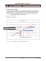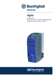
1
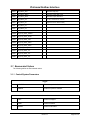
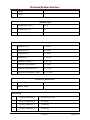
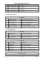
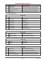
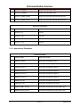
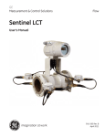
CN32Pt, CN16Pt, CN16PtD, CN8Pt, CN8PtD
DP32Pt, DP16Pt, DP8Pt
MODBUS Interface
The information contained in this document is believed to be correct, but OMEGA accepts no liability for any errors it contains, and
reserves the right to alter specifications without notice.
Platinum Modbus Interface
Table of Contents
1
Introduction ........................................................................................................... 2
1.1
1.2
1.3
2
Purpose ....................................................................................................................2
Definition of Terms and Acronyms ........................................................................2
Applicable Documents ............................................................................................3
Modbus Interface .................................................................................................. 4
2.1
2.2
Modbus Functions ..................................................................................................4
Data Formats ...........................................................................................................4
2.2.1
2.2.2
2.2.3
2.2.4
3
Multiple Register Reads ........................................................................................................ 4
Multiple Register Writes ........................................................................................................ 5
Request Packet Sizes ........................................................................................................... 5
Modbus USB Support ........................................................................................................... 6
Platinum Modbus Register Assignments ........................................................... 7
3.1
Enumerated Values ...............................................................................................16
3.1.1
3.1.2
3.1.3
3.1.4
3.1.5
3.1.6
3.1.7
3.1.8
3.1.9
3.1.10
3.1.11
3.1.12
3.1.13
Control/System Parameters ................................................................................................ 16
Simulator Parameters ......................................................................................................... 17
Display & Formatting ........................................................................................................... 18
Ramp and Soak Parameters ............................................................................................... 19
Input Parameters ................................................................................................................. 20
Setpoint Parameters ........................................................................................................... 22
Alarm Parameters ............................................................................................................... 22
Output Parameters .............................................................................................................. 23
Annunciator Parameters ..................................................................................................... 24
Communication Parameters ............................................................................................ 25
Excitation Parameters ..................................................................................................... 26
Calibration Parameters ................................................................................................... 26
Input / Output Scaling ...................................................................................................... 27
Revision 0.1
Page 1 of 27
Platinum Modbus Interface
1 Introduction
1.1 Purpose
The following document defines the Modbus protocol support and register mapping used by the
Platinum product family.
The Modbus interface is available on all communication channels and support is provided for
MODBUS/ASCII, MODBUS/RTU and MODBUS/TCP/IP transactions.
1.2 Definition of Terms and Acronyms
I2C
2 wire serial interface
Base Device
Device connected to slave device
Smart Input
Device supporting 1 or more Input sensors
Smart Output
Device supporting 1 or more Output Elements
Sensor Element
One of the physical sensing elements on a Smart Output
AC
Alternating Current
DC
Direct Current
CS
Chip Select
ADC
Analog to Digital Converter
DAC
Digital to Analog Converter
RS485
Electrical signals used for serial communications
RS232
Electrical signals used for serial communications
CSV
Comma Separated Values
COTS
Commercially-Off-The-Shelf
ESD
Electo Static Discharge
FW
Firmware
HW
Hardware
I/O
Input/Output
LED
Light Emitting Diode
Hexadecimal
Values expressed using base 16 (24)
Revision 0.1
Page 2 of 27
Platinum Modbus Interface
1.3 Applicable Documents
Doc. #
Name / Description
Rev. #
Platinum Load and Save File Format
0.0.1
Platinum Ramp and Soak Processing
MODBUS APPLICATION PROTOCOL SPECIFICATION
0.0.1
V1.1b3
Device Serialization and Version Information
Rev 0.1
Omega Engineering Coding Standard
Rev 1.2.0
Revision 0.1
Page 3 of 27
Platinum Modbus Interface
2 Modbus Interface
The Modbus interface is fully described in MODBUS APPLICATION PROTOCOL SPECIFICATION
(V1.1b3).
The Modbus specification allows accessing to up 65535 internal ‘holding’ registers using register
READ, register WRITE and WRITE MULTIPLE commands. Each Modbus holding register is defined
as a 16 bit entity structured as BIG ENDIAN values (most significant byte always presented first).
The Platinum Modbus interface provides access to the internal database of the Platinum product
family by internally mapping Modbus holding registers to specific database items.
Modbus is structured using a MASTER-SLAVE topology, in which there is one MASTER device and
up to 255 slave devices. All transactions are initiated by the MASTER device.
Modbus slave devices are individually accessed using a one byte SLAVE address. The MASTER
device initiates a transaction by sending a request packet to a specific slave. The SLAVE device
processes the transaction and returns either response packet indicating success or failure.
Address 0 is reserved as a ‘broadcast’ address, in which all slave devices will accept and process the
transaction but will not send a response.
2.1 Modbus Functions
The Platinum Modbus interface supports the following Modbus FUNCTION requests.
Function
Code
Mnemonic
Description
0x03
Read Holding Register
Reads one or more consecutive 16 bit holding registers
0x06
Write Single Register
Writes a specific 16 bit holding register
0x07
Read Exception status
Reads structured status information
0x08
Diagnostic
Read/Write diagnostic information
0x10
Write Multiple Registers
Write one or more consecutive 16 bit holding registers
0x0b
Get Comm events
Read communication event counters
2.2 Data Formats
Modbus holding registers are represented as 16 bit entities. The following encoding is used for
extended data items. Note that ‘byte 0’ will be the first byte received/transmitted.
For data types that can be represented in 16 bit (Boolean, byte, char, int16 and uint16) a single
register is used.
For data types that require 32 bits two consecutive registers are used. The lower number register will
represent the most significant data. The 2nd register represents the leas significant data.
2.2.1 Multiple Register Reads
When reading a dual register entity the lower order register should be used as the requested ‘holdiing
register’, with a request for a minimum of 2 registers. Internally the entire entity is read and data is
then built into a response packet.
The access can be split into 2 consecutive single register reads. When the lower (base) register is
accessed the entire 32 bit entity is read and the two most significant bytes are returned. The following
Revision 0.1
Page 4 of 27
Platinum Modbus Interface
single register read must specify the next consecutive register address. The two least significant
bytes of the internally buffered data used in the response.
Attempts to access the two least significant bytes without first reading the two most significant bytes
will result in an error response.
2.2.2 Multiple Register Writes
When writing a dual register entity the lower order register should be used as the requested ‘holdiing
register’, with a request for minimum of 2 registers. The write data is internally buffered and
transferred to the database entry as a 32 bit value.
The access can be split into 2 consecutive single register writes. When the lower (base) register is
written the 16 bit entity is internally buffered BUT NO DATA TRANSFER IS MADE TO THE
DATABASE. The following single register write must specify the next consecutive register address.
The two least significant bytes of the write request are combined with the previous write data and the
entire 32 bit entity is written to the database.
Attempts to write the two least significant bytes without first writing the two most significant bytes will
result in an error response.
Data
Types
Number
of
Registers
0
1
Boolean
1
--
LSB
Byte,
Char
1
--
LSB
Int16,
uint16
1
Byte
Description
2
3
Zero = OFF, non-zero = ON
N/A
Entity contained in LSB of register,
Byte 0 ignored.
MSB
LSB
Entity contained in MSB/LSB of
register.
0
1
2
3
(dual register data)
Int32,
uint32
2
MSB
B-1
B-2
LSB
Requires 2 consecutive registers,
MSB transferred first
float
2
Sign+
Exp
Mantisa
MSB
B-1
Mantisa
LSB
IEEE formatted value contained in 2
consecutive register
2.2.3 Request Packet Sizes
Multiple consecutive registers may be accessed in a single transaction.
The Platinum Modbus interface imposes a maximum of 64 bytes for the total transaction. Allowing for
the required framing, addressing and integrity checks results in the following data size restrictions
using the READ and WRITE MULTIPLE functions.
Format
Protocol Overhead
Maximum Read data
Maximum Write data
ASCII
16
12 Registers
12 Registers
RTU
8
23 Registers
23 Registers
TCP/IP
8
23 Registers
23 Registers
Revision 0.1
Page 5 of 27
Platinum Modbus Interface
2.2.4 Modbus USB Support
The Modbus specification supports RS232 and RS485 serial data. For ASCII formatted packets a
USB virtual comm channel provides full support since the framing information is specified by unique
characters (SOF = ‘:’, EOF = CR/LF).
For RTU formatted packets the Modbus requires specific inter-frame character timing to determine
the framing of each transaction. This information is not available using a generic virtual comm
channel across USB, which will typically collect ‘serial’ data into 64 byte packets for transmission, as
determined by the USB end-point buffer size. The USB Modbus RTU interface relies on the USB
channel collecting data into 64 byte packets.
Revision 0.1
Page 6 of 27
Platinum Modbus Interface
3 Platinum Modbus Register Assignments
All accesses to the Platinum database information is made thru the following Modbus registers.
Mnemonic entries marked with ‘*’ are identical to those used by the Platinum LOAD and SAVE file
formats.
Mnemonic entries marked with ‘**’ are identical to those used by the Platinum LOAD and SAVE file
formats but are referenced in LOAD and FILE data are made using meta characters (%).
Data types are:
R – single 16 bit register (may be Boolean, byte, char, int16 or uint16 data)
L – dual (32 bit) register (may be int32 or uint32 data)
F – IEEE Floating point value
All data is transferred using Big Endian formatting, where the most significant byte is transmitted first.
Index
Mnemonic
Type
Description
0x0200
DEVICE_ID**
L
Device Identifier
0x0202
VERSION_NUMBER**
L
0x0204
SYSTEM_STATUS
L
0x0210
CURRENT_INPUT_VALUE
F
0x0212
REMOTE_SENSOR_VALUE
F
0x0214
REMOTE_SETPOINT_VALUE
F
0x021e
INPUT_DIGITAL
R
State of digital input pin
0x0224
CONTROL_SETPOINT
F
Setpoint used in PID calculations
0x0226
PEAK_VALUE
F
Maximum Value processed
0x0228
VALLEY_VALUE
F
Minimum Value processed
0x022a
PID_OUTPUT
F
PID Output level (0..100%)
0x022c
CURRENT_INPUT_VALID
R
Flag indicating process value is valid
0x022d
ALARM_STATE
L
0x022e
RAMP_SOAK_STATE
R
Enumerated value - R&S state
0x0230
OUTPUT_1_STATE
R
Flag indicating state of Output (0/1)
0x0231
OUTPUT_2_STATE
R
Flag indicating state of Output (0/1)
0x0232
OUTPUT_3_STATE
R
Flag indicating state of Output (0/1)
0x0233
OUTPUT_4_STATE
R
Flag indicating state of Output (0/1)
0x0234
DISPLAY_ALARM_CONTROL
R
0x0240
RUN_MODE
R
Enumerated value – system running state
0x0241
FACTORY_RESET
R
Write 1 to force reset to factory defaults
0x0242
LATCH_RESET
R
Write 1 to reset latched alarms
0x0243
PID_AUTOTUNE_START
R
Write 1 to force Autotuning to start
0x0244
PID_AUTOTUNE_DONE
R
Internal use only
Internal Use Only
Revision 0.1
Page 7 of 27
Platinum Modbus Interface
0x0248
READING_DECIMAL_POSITION*
R
Enumerated value – number of dec. points
0x0249
DISPLAY_UNITS*
R
Enumerated value – units of measure
0x024a
DISPLAY_COLOR_NORMAL*
R
Enumerated value to set display color
0x024b
DISPLAY_BRIGHTNESS*
R
Enumerated value to set display brightness
0x024c
TIME_FORMAT*
R
Enumerated value to indicate time format
0x0250
TCAL_TYPE*
R
Enumerated value indicating type of TCAL
0x0251
SET_ICE_POINT
R
Write 1 to set ICE POINT offset
0x0252
SET_TCAL_1_POINT
R
Write 1 to set 1 point Cal. offset
0x0253
SET_TCAL_2_POINT_LOW
R
Write 1 to set 2 point Cal. LOW point
0x0254
SET_TCAL_2_POINT_HIGH
R
Write 1 to set 2 point Cal. HIGH point
0x0258
TCAL_ICE_POINT_OFFSET*
F
Stored ICE POINT offset
0x025a
TCAL_1_POINT_OFFSET*
F
Stored 1 point CAL offset
0x025c
TCAL_2_POINT_OFFSET*
F
Stored 2 point CAL offset
0x025e
TCAL_2_POINT_GAIN*
F
Stored 2 point CAL gain
0x0260
RAMP_SOAK_MODE*
R
Enumerated – Ramp and Soak mode
0x0261
RAMP_SOAK_PROFILE_SELECT*
R
Starting Profile for Ramp and Soak
0x0262
CURRENT_PROFILE
R
Use to select R&S profile to access
0x0263
CURRENT_SEGMENT
R
Use to select profile segment to access
0x0264
SEGMENTS_PER_PROFILE*
R
Number of segments in current profile
0x0265
SOAK_ACTION*
R
Enumerated – Soak Action
0x0266
SOAK_LINK*
R
Profile to link to after current profile
0x0267
TRACKING_TYPE*
R
Enumerated – R&S tracking type
0x0268
RAMP_EVENT*
R
RE.ON flag set for current segment
0x0269
SOAK_EVENT*
R
SE.ON flag set for current segment
0x026a
SOAK_PROCESS_VALUE*
F
Target SOAK setpoint for current segment
0x026c
RAMP_TIME*
L
Time (msec) to reach target SOAK setpoint
0x026e
SOAK_TIME*
L
Time (msec) to hold at SOAK setpoint
0x0270
CONTROL_SETPOINT
F
Setpoint used for PID/Control functions
0x0272
RAMP_SOAK_REMAINING_TIME
L
Ramp or Soak time remaining
0x0274
RAMP_SOAK_STATE
R
Enumerated – R&S flags
0x0280
CURRENT_INPUT_VALUE
F
Current Process value
Revision 0.1
Page 8 of 27
Platinum Modbus Interface
0x0282
INPUT_SENSOR*
R
Enumerated sensor (input) type
0x0283
TC_TYPE*
R
Enumerated Thermocouple type
0x0284
RTD_WIRE*
R
Enumerated RTD wire type
0x0285
RTD_ACRV_OHM_TYPE*
R
Enumerated RTD Curve
0x0286
THERMISTOR_VALUE*
R
Enumerated Thermistor type
0x0287
PROCESS_RANGE*
R
Enumerated process input range
0x028f
READING_FILTER_CONSTANT*
R
Enumerated input filtering constant
0x02a0
PID_ADAPTIVE_CONTROL_ENABLE*
R
Enumerated Toggle
0x02a1
PID_ACTION*
R
Enumerated PID control action
0x02a2
PID_AUTOTUNE_TIMEOUT*
L
Timeout (msec) for autotuning
0x02a4
PID_P_*
F
Proportional Gain value
0x02a6
PID_I_*
F
Integral Gain value
0x02a8
PID_D_*
F
Derivative Gain value
0x02aa
PID_PERCENT_LOW*
F
Minimum PID Control output value
0x02ac
PID_PERCENT_HIGH*
F
Maximum PID Control output value
0x02ae
PID_MAX_RATE*
F
PID maximum rate of change
0x02b0
PID_ STABILITY_TIMEOUT*
L
Autotune stability test timeout
0x02b2
PID_ STABILITY_RATE*
F
Autotune maximum rate of change stabilitytest
0x02c0
SAFETY_DELAYED_POWER_ON_RUN*
R
Write 1 to DISABLE auto RUN on power up
0x02c1
SAFETY_DELAYED_OPER_RUN*
R
Write 1 to DISABLE return to RUN in OPER
0x02c2
SAFETY_SETPOINT_LIMIT_LOW*
F
Minimum allowed setpoint value
0x02c4
SAFETY_SETPOINT_LIMIT_HIGH*
F
Maximum allowed setpoint value
0x02c6
LOOP_BREAK_ENABLE*
R
Enumerated Toggle
0x02c8
LOOP_BREAK_TIME*
L
Time (msec) for break test
0x02ca
OPEN_CIRCUIT_ENABLE*
R
Write 1 to enable open circuit test
0x02d0
PASSWORD_INIT_ENABLE*
R
Write 1 to enable INIT menu password
0x02d2
PASSWORD_INIT*
L
INIT menu password
0x02d4
PASSWORD_PROGRAM_ENABLE*
R
Write 1 to enable PROG menu password
0x02d6
PASSWORD_PROGRAM*
L
PROG menu password
0x02e0
SETPOINT_1_MODE*
R
Enumerated Setpoint 1 mode
0x02e2
SETPOINT_1*
F
Setpoint 1 value
Revision 0.1
Page 9 of 27
Platinum Modbus Interface
0x02e8
SETPOINT_2_MODE*
R
Enumerated Setpoint 2 mode
0x02ea
ABSOLUTE_SETPOINT_2*
F
Setpoint 2 value (absolute mode)
0x02ec
DEVIATION_SETPOINT_2*
F
Setpoint 2 value (derivative mode)
0x0300
DB_4_20_MANUAL_LIVE*
R
Enumerated Input Process mode
0x0302
DB_4_20_MANUAL_READING_1*
F
Manual Scale reading value 1
0x0304
DB_4_20_MANUAL_INPUT_1*
F
Manual Scale input value 1
0x0306
DB_4_20_MANUAL_READING_2*
F
Manual Scale reading value 2
0x0308
DB_4_20_MANUAL_INPUT_2*
F
Manual Scale input value 2
0x030a
DB_4_20_LIVE_READING_1*
F
Live Scale reading value 1
0x030c
DB_4_20_LIVE_INPUT_1*
F
Live Scale input value 1
0x030e
DB_4_20_LIVE_READING_2*
F
Live Scale reading value 2
0x0310
DB_4_20_LIVE_INPUT_2*
F
Live Scale input value 2
0x0320
DB_0_24_MANUAL_LIVE*
R
Enumerated Input Process mode
0x0322
DB_0_24_MANUAL_READING_1*
F
Manual Scale reading value 1
0x0324
DB_0_24_MANUAL_INPUT_1*
F
Manual Scale input value 1
0x0326
DB_0_24_MANUAL_READING_2*
F
Manual Scale reading value 2
0x0328
DB_0_24_MANUAL_INPUT_2*
F
Manual Scale input value 2
0x032a
DB_0_24_LIVE_READING_1*
F
Live Scale reading value 1
0x032c
DB_0_24_LIVE_INPUT_1*
F
Live Scale input value 1
0x032e
DB_0_24_LIVE_READING_2*
F
Live Scale reading value 2
0x0330
DB_0_24_LIVE_INPUT_2*
F
Live Scale input value 2
0x0340
DB_10_MANUAL_LIVE*
R
Enumerated Input Process mode
0x0342
DB_10_MANUAL_READING_1*
F
Manual Scale reading value 1
0x0344
DB_10_MANUAL_INPUT_1*
F
Manual Scale input value 1
0x0346
DB_10_MANUAL_READING_2*
F
Manual Scale reading value 2
0x0348
DB_10_MANUAL_INPUT_2*
F
Manual Scale input value 2
0x034a
DB_10_LIVE_READING_1*
F
Live Scale reading value 1
0x034c
DB_10_LIVE_INPUT_1*
F
Live Scale input value 1
0x034e
DB_10_LIVE_READING_2*
F
Live Scale reading value 2
0x0350
DB_10_LIVE_INPUT_2*
F
Live Scale input value 2
0x0360
DB_1_MANUAL_LIVE*
R
Enumerated Input Process mode
0x0362
DB_1_MANUAL_READING_1*
F
Manual Scale reading value 1
Revision 0.1
Page 10 of 27
Platinum Modbus Interface
0x0364
DB_1_MANUAL_INPUT_1*
F
Manual Scale input value 1
0x0366
DB_1_MANUAL_READING_2*
F
Manual Scale reading value 2
0x0368
DB_1_MANUAL_INPUT_2*
F
Manual Scale input value 2
0x036a
DB_1_LIVE_READING_1*
F
Live Scale reading value 1
0x036c
DB_1_LIVE_INPUT_1*
F
Live Scale input value 1
0x036e
DB_1_LIVE_READING_2*
F
Live Scale reading value 2
0x0370
DB_1_LIVE_INPUT_2*
F
Live Scale input value 2
0x0380
DB_POINT_1_MANUAL_LIVE*
R
Enumerated Input Process mode
0x0382
DB_POINT_1_MANUAL_READING_1*
F
Manual Scale reading value 1
0x0384
DB_POINT_1_MANUAL_INPUT_1*
F
Manual Scale input value 1
0x0386
DB_POINT_1_MANUAL_READING_2*
F
Manual Scale reading value 2
0x0388
DB_POINT_1_MANUAL_INPUT_2*
F
Manual Scale input value 2
0x038a
DB_POINT_1_LIVE_READING_1*
F
Live Scale reading value 1
0x038c
DB_POINT_1_LIVE_INPUT_1*
F
Live Scale input value 1
0x038e
DB_POINT_1_LIVE_READING_2*
F
Live Scale reading value 2
0x0390
DB_POINT_1_LIVE_INPUT_2*
F
Live Scale input value 2
0x03d0
RSP_PROCESS_RANGE*
R
Enumerated Process Range
0x03d2
RSP_ENABLE*
R
Enumerated Toggle (sets SP 1 mode)
0x03d8
RSP_4_20_SETPOINT_MIN*
F
Minimum Setpoint
0x03da
RSP_4_20_INPUT_MIN*
F
Minimum Input
0x03dc
RSP_4_20_SETPPOINT_MAX*
F
Maximum Setpoint
0x03de
RSP_4_20_INPUT_MAX*
F
Maximum Input
0x03e0
RSP_0_24_SETPOINT_MIN*
F
0x03e2
RSP_0_24_INPUT_MIN*
F
0x03e4
RSP_0_24_SETPPOINT_MAX*
F
0x03e6
RSP_0_24_INPUT_MAX*
F
0x03e8
RSP_0_10_SETPOINT_MIN*
F
0x03ea
RSP_0_10_INPUT_MIN*
F
0x03ec
RSP_0_10_SETPOINT_MAX*
F
0x03ee
RSP_0_10_INPUT_MAX*
F
0x03f0
RSP_0_1_SETPOINT_MIN*
F
0x03f2
RSP_0_1_INPUT_MIN*
F
0x03f4
RSP_0_1_SETPOINT_MAX*
F
0x03f6
RSP_0_1_INPUT_MAX*
F
Revision 0.1
Page 11 of 27
Platinum Modbus Interface
0x0400
OUTPUT_1_HW_TYPE
R
Enumerated Hardware Type
0x0401
OUTPUT_1_MODE*
R
Enumerated Output Mode
0x0402
OUTPUT_1_ON_OFF_ACTION*
R
Enumerated On-Off Action
0x0403
OUTPUT_1_SETPOINT*
R
Output Setpoint selection
0x0404
OUTPUT_1_PULSE_LENGTH*
F
Pulse Length (.1 sec increments)
0x0406
OUTPUT_1_ON_OFF_DEADBAND*
F
Deadband
0x0408
OUTPUT_1_OUTPUT_RANGE*
R
Enumerated Output Analog Range
0x040a
OUTPUT_1_RETRAN_READING_1*
F
Retransmission Reading Low
0x040c
OUTPUT_1_RETRAN_OUTPUT_1*
F
Output Level Low
0x040e
OUTPUT_1_RETRAN_READING_2*
F
Retransmission Reading High
0x0410
OUTPUT_1_RETRAN_OUTPUT_2*
F
Output Level High
0x0420
OUTPUT_2_HW_TYPE
R
0x0421
OUTPUT_2_MODE*
R
0x0422
OUTPUT_2_ON_OFF_ACTION*
R
0x0423
OUTPUT_2_SETPOINT*
R
0x0424
OUTPUT_2_PULSE_LENGTH*
F
0x0426
OUTPUT_2_ON_OFF_DEADBAND*
F
0x0428
OUTPUT_2_OUTPUT_RANGE*
R
0x042a
OUTPUT_2_RETRAN_READING_1*
F
0x042c
OUTPUT_2_RETRAN_OUTPUT_1*
F
0x042e
OUTPUT_2_RETRAN_READING_2*
F
0x0430
OUTPUT_2_RETRAN_OUTPUT_2*
F
0x0440
OUTPUT_3_HW_TYPE
R
0x0441
OUTPUT_3_MODE*
R
0x0442
OUTPUT_3_ON_OFF_ACTION*
R
0x0443
OUTPUT_3_SETPOINT*
R
0x0444
OUTPUT_3_PULSE_LENGTH*
F
0x0446
OUTPUT_3_ON_OFF_DEADBAND*
F
0x0448
OUTPUT_3_OUTPUT_RANGE*
R
0x044a
OUTPUT_3_RETRAN_READING_1*
F
0x044c
OUTPUT_3_RETRAN_OUTPUT_1*
F
0x044e
OUTPUT_3_RETRAN_READING_2*
F
0x0450
OUTPUT_3_RETRAN_OUTPUT_2*
F
Revision 0.1
Page 12 of 27
Platinum Modbus Interface
0x0460
OUTPUT_4_HW_TYPE
R
0x0461
OUTPUT_4_MODE*
R
0x0462
OUTPUT_4_ON_OFF_ACTION*
R
0x0463
OUTPUT_4_SETPOINT*
R
0x0464
OUTPUT_4_PULSE_LENGTH*
F
0x0466
OUTPUT_4_ON_OFF_DEADBAND*
F
0x0468
OUTPUT_4_OUTPUT_RANGE*
R
0x046a
OUTPUT_4_RETRAN_READING_1*
F
0x046c
OUTPUT_4_RETRAN_OUTPUT_1*
F
0x046e
OUTPUT_4_RETRAN_READING_2*
F
0x0470
OUTPUT_4_RETRAN_OUTPUT_28
F
0x0500
ALARM_STATE
R
Alarm state (Bit 0)
0x0501
ALARM_1_TYPE*
R
Enumerated Alarm type
0x0502
ALARM_1_MODE*
R
Enumerated Alarm Mode
0x0503
ALARM_1_DISPLAY_COLOR*
R
Enumerated Alarm Color
0x0504
ALARM_1_HIGH_HIGH_MODE*
R
Enumerated Toggle value
0x0505
ALARM_1_LATCH_TYPE*
R
Enumerated Toggle value
0x0506
ALARM_1_CONTACT_CLOSURE_TYPE*
R
Enumerated Contact closure type
0x0507
ALARM_1_POWER_ON_STATE*
R
Enumerated Power on control
0x0508
ABSOLUTE_ALARM_1_LOW*
F
Alarm Low value (Absolute mode)
0x050a
ABSOLUTE_ALARM_1_HIGH*
F
Alarm High value (Absolute mode)
0x050c
DEVIATION_ALARM_1_LOW*
F
Alarm Low offset (Deviation mode)
0x050e
DEVIATION_ALARM_1_HIGH*
F
Alarm High offset (Deviation mode)
0x0510
ALARM_1_HIGH_HIGH_OFFSET*
F
Alarm High-High offset
0x0512
ALARM_1_ON_DELAY*
F
Alarm On Delay
0x0514
ALARM_1_OFF_DELAY*
F
Alarm Off Delay
0x0520
ALARM_STATE
R
0x0521
ALARM_2_TYPE*
R
0x0522
ALARM_2_MODE*
R
0x0523
ALARM_2_DISPLAY_COLOR*
R
0x0524
ALARM_2_HIGH_HIGH_MODE*
R
0x0525
ALARM_2_LATCH_TYPE*
R
0x0526
ALARM_2_CONTACT_CLOSURE_TYPE*
R
Revision 0.1
Page 13 of 27
Platinum Modbus Interface
0x0527
ALARM_2_POWER_ON_STATE*
R
0x0528
ABSOLUTE_ALARM_2_LOW*
F
0x052a
ABSOLUTE_ALARM_2_HIGH*
F
0x052c
DEVIATION_ALARM_2_LOW*
F
0x052e
DEVIATION_ALARM_2_HIGH*
F
0x0530
ALARM_2_HIGH_HIGH_OFFSET*
F
0x0532
ALARM_2_ON_DELAY*
F
0x0534
ALARM_2_OFF_DELAY*
F
0x05c0
EXCITATION_VOLTAGE*
R
Enumerated Excitation Voltage
0x05e0
DB_ANNUNCIATOR_STATE
R
Enumerated Annunciator State
0x05e1
DB_ANNUNCIATOR_1_MODE*
R
Enumerated Annunciator Mode
0x05e4
DB_ANNUNCIATOR_STATE
R
Enumerated Annunciator State
0x05e5
DB_ANNUNCIATOR_2_MODE*
R
Enumerated Annunciator Mode
0x0600
USB_PROTOCOL*
R
Enumerated Comm Mode
0x0601
USB_RECOGNITION_CHARACTER*
R
Recognition character
0x0602
USB_DATA_FLOW*
R
Enumerated Data Flow (Omega mode)
0x0603
USB_ECHO_MODE*
R
Enumerated Toggle value
0x0604
USB_CONTINUOUS_DATA_PERIOD*
F
Time interval in continuous mode (0.1 sec)
0x0606
USB_DATA_FORMAT_STATUS*
R
Enumerated Toggle value
0x0607
USB_DATA_FORMAT_READING*
R
Enumerated Toggle value
0x0608
USB_DATA_FORMAT_PEAK*
R
Enumerated Toggle value
0x0609
USB_DATA_FORMAT_VALLEY*
R
Enumerated Toggle value
0x060a
USB_DATA_FORMAT_UNIT*
R
Enumerated Toggle value
0x060b
USB_SEPARATION_CHAR*
R
Enumerated Separation character
0x060c
USB_LINE_FEED*
R
Enumerated Toggle value
0x060d
USB_DEVICE_ADDRESS*
R
Byte address (0..255)
0x060e
USB_MODBUS_MODE*
R
Enumerated Modbus mode
0x060f
USB_MODBUS_EOL*
R
2 character EOL character string (CR/LF)
0x0620
ETH_PROTOCOL*
R
0x0621
ETH_RECOGNITION_CHARACTER*
R
0x0622
ETH_DATA_FLOW*
R
Revision 0.1
Page 14 of 27
Platinum Modbus Interface
0x0623
ETH_ECHO_MODE*
R
0x0624
ETH_CONTINUOUS_DATA_PERIO*
F
0x0626
ETH_DATA_FORMAT_STATUS*
R
0x0627
ETH_DATA_FORMAT_READING*
R
0x0628
ETH_DATA_FORMAT_PEAK*
R
0x0629
ETH_DATA_FORMAT_VALLEY*
R
0x062a
ETH_DATA_FORMAT_UNIT*
R
0x062b
ETH_LINE_FEED*
R
0x062c
ETH_SEPARATION_CHAR*
R
0x062d
ETH_DEVICE_ADDRESS*
R
0x062e
ETH_MODBUS_MODE*
R
0x062f
ETH_MODBUS_EOF*
R
0x0640
SERIAL_PROTOCOL*
R
0x0641
SERIAL_RECOGNITION_CHARAC*
R
0x0642
SERIAL_DATA_FLOW*
R
0x0643
SERIAL_ECHO_MODE*
R
0x0644
SERIAL_CONTINUOUS_DATA_PE*
R
0x0646
SERIAL_DATA_FORMAT_STATUS*
F
0x0647
SERIAL_DATA_FORMAT_READIN*
R
0x0648
SERIAL_DATA_FORMAT_PEAK*
R
0x0649
SERIAL_DATA_FORMAT_VALLEY*
R
0x064a
SERIAL_DATA_FORMAT_UNIT*
R
0x064b
SERIAL_LINE_FEED*
R
0x064c
SERIAL_SEPARATION_CHAR*
R
0x064d
SERIAL_DEVICE_ADDRESS*
R
0x064e
SERIAL_MODBUS_MODE*
R
0x064f
SERIAL_MODBUS_EOF*
R
0x0650
SERIAL_232_485*
R
Enumerated serial interface type
0x0651
SERIAL_BAUD_RATE*
R
Enumerated baud rate value
0x0652
SERIAL_PARITY*
R
Enumerated parity value
0x0653
SERIAL_DATABITS*
R
Enumerated databits value
0x0654
SERIAL_STOPBITS*
R
Enumerated stopbits value
0x06c0
SIM_INPUT_MODE*
R
Enumerated Simulator mode
0x06c1
SIM_INPUT_RATE*
R
Adjustment rated (.05 seconds)
Revision 0.1
Page 15 of 27
Platinum Modbus Interface
0x06c2
SIM_INPUT_ADJ*
F
Simulator Adj/step
0x06c4
SIM_INPUT_MAX*
F
Simulator Input Max Value
0x06c6
SIM_INPUT_MIN*
F
Simulator Input Min Value
0x06c8
SIM_INPUT_C0*
F
Y = C0 + C1*X+C22*X + C33*X
0x06ca
SIM_INPUT_C1*
F
(special case for Plant model)
0x06cc
SIM_INPUT_C2*
F
0x06ce
SIM_INPUT_C3*
F
0x06d0
SIM_AUX_INPUT_MODE*
R
0x06d1
SIM_AUX_INPUT_RATE*
R
0x06d2
SIM_AUX_INPUT_ADJ*
F
0x06d4
SIM_AUX_INPUT_MAX*
F
0x06d6
SIM_AUX_INPUT_MIN*
F
0x06d8
SIM_AUX_INPUT_C0*
F
0x06da
SIM_AUX_INPUT_C1*
F
0x06dc
SIM_AUX_INPUT_C2*
F
0x06de
SIM_AUX_INPUT_C3*
F
3.1 Enumerated Values
The following define the Enumerated values.
3.1.1 Control/System Parameters
Toggle
0
DISABLE
Feature or option is disabled
1
ENABLE
Feature or option is enabled
Control
0
STOP
Control is stopped
1
START
Control is started
2
CANCEL
Control is cancelled
Revision 0.1
Page 16 of 27
Platinum Modbus Interface
3
AUTO_ON
Control is immediated started
4
CONTINUOUS
Control is continuously (repeatedly) enabled
Control Action
0
ACTION_REVERSE
Output active if P.V. < Setpoint
1
ACTION_DIRECT
Output active if P.V. > Setpoint
System State
0
LOAD
File transfer in progress
1
IDLE
Idle, no control
2
INPUT_ADJUST
Adjusting input value
3
CONTROL_ADJUST
Adjusting output value
4
MODIFY
Modify parameter in OPER mode
5
WAIT
Waiting for RUN condition
6
STANDBY
Standby mode
7
STOP
Stopped mode
8
PAUSE
Paused mode
9
FAULT
Fault detected
10
SHUTDOWN
Shutdown condition detected
11
AUTOTUNE
Autotune in progress
3.1.2 Simulator Parameters
Simulation Mode
0
STOPPED
Simulator is stopped
1
PAUSED
Simulator is paused
2
TRIANGLE
Triangle output
3
SAW
Sawtooth output
Revision 0.1
Page 17 of 27
Platinum Modbus Interface
4
INVERTED
Inverted Sawtooth output
5
PLANT
Simulated Plant
3.1.3 Display & Formatting
Time Format
0
MINUTE_SECOND
MM.SS displayed
1
HOUR_MINUTE
HH.MM displayed
2
MILLISECONDS
S.MMM displayed
Decimal Point
0
DECIMAL_POINT_NONE
Display as XXXX
1
DECIMAL_POINT_3
Display as XXX.X
2
DECIMAL_POINT_2
Display as XX.XX
3
DECIMAL_POINT_1
Display as X.XXX
Units
0
UNIT_NONE
No units applied
1
UNIT_CELCIUS
Values converted to oC
2
UNIT_FARENHEIT
Values converted to oF
Color
0
COLOR_OFF
No color
1
COLOR_GREEN
GREEN
2
COLOR_RED
RED
3
COLOR_AMBER
AMBER
4
COLOR_NO_CHANGE
Do not change color (internal use)
Brightness
Revision 0.1
Page 18 of 27
Platinum Modbus Interface
0
BRIGHTNESS_LOW
1
BRIGHTNESS_MEDIUM
2
BRIGHTNESS_HIGH
3.1.4 Ramp and Soak Parameters
Ramp & Soak State (bit mapped)
0x00
INACTIVE
Ramp & Soak is inactive
0x01
RAMPING
Ramp time and RE bit set
0x02
SOAKING
Soak time and SE bit set
0x04
RAMP_ACTIVE
Ramp time
0x08
SOAK_ACTIVE
Soak time
0x10
RAMP_SOAK_PAUSED
Ramp & Soak is in PAUSE condition
0x80
RAMP_SOAK_ERROR
Ramp & Soak error condition
Ramp & Soak Tracking
0
FIXED_RAMP
Fixed RAMP time
1
FIXED_SOAK
Fixed SOAK time
2
FIXED_CYCLE
Fixed CYCLE time
Ramp & Soak Link Action
0
STOP_PROCESS
Stop at end of profile
1
HOLD_PROCESS
Hold last SOAK level at end of profile
2
LINK_PROFILE
Link to Profile defined in LINK field
Ramp & Soak Control
0
RAMP_SOAK_DISABLED
Disabled
1
RAMP_SOAK_ENABLED
Enabled by RUN button
Revision 0.1
Page 19 of 27
Platinum Modbus Interface
2
RAMP_SOAK_REMOTE
Enabled by RUN button or Digital Input
3.1.5 Input Parameters
Sensor Type
0
SENSOR_TC
Thermocouple
1
SENSOR_RTD
RTD
2
SENSOR_PROCESS
Process Input
3
SENSOR_THERMISTOR
Thermistor
4
SENSOR_REMOTE
Remote
Thermocouple Types
0
J
6
R
1
K
7
S
2
T
8
B
3
E
9
C
4
N
10
<RESERVED>
5
<RESEREVED>
11
<RESERVED>
RTD ACRV OHM Types
0
385_100
385 Curve, 100 ohms
1
385_500
385 Curve, 500 ohms
2
385_1000
385 Curve, 1000 ohms
3
392_100
392 Curve, 100 ohms
4
3916_100
3916Curve, 100 ohms
RTD Wire types
0
2_WIRE
Revision 0.1
Page 20 of 27
Platinum Modbus Interface
1
3_WIRE
2
4_WIRE
Thermistor Type
0
THERMISTOR_2_25_K
2.25 K
1
THERMISTOR_5_K
5K
2
THERMISTOR_10_K
10K
Process Input Types
0
PROCESS_4_20
4 – 20 mA
1
PROCESS_0_24
0 – 24 mA
2
PROCESS_0_10
0 – 10 Vdc
3
PROCESS_0_1
0 – 1.0 Vdc
2
PROCESS_0_POINT_1
0 – 0.1 Vdc
5
PROCESS_PLUS_MINUS_1
+/– 10 Vdc
6
PROCESS_PLUS_MINUS_10
+/ – 1.0 Vdc
7
PROCESS_PLUS_MINUS_POINT_1
+/ – 0.1 Vdc
Process Live_Manual mode
0
LIVE_MODE
1
MANUAL_MODE
Input Filtering
0
FILTER_CONSTANT_1
No filtering (1 X rate)
1
FILTER_CONSTANT_2
X 2 filtering
2
FILTER_CONSTANT_4
X 4 filtering
3
FILTER_CONSTANT_8
X 8 filtering
Revision 0.1
Page 21 of 27
Platinum Modbus Interface
4
FILTER_CONSTANT_16
X 16 filtering
5
FILTER_CONSTANT_32
X 32 filtering
6
FILTER_CONSTANT_64
X 64 filtering
7
FILTER_CONSTANT_128
X 128 filtering
3.1.6 Setpoint Parameters
Setpoint Modes
0
SETPOINT_ABSOLUTE
Setpoint value given as fixed constant
1
SETPOINT_DEVIATION
Setpoint value is deviation (+/-) Setpoint 1 value
2
SETPOINT_REMOTE
Setpoint 1 set by Remote Setpoint
3
SETPOINT_EXTERNAL
Setpoint value set externally
4
SETPOINT_RAMP_SOAK
Setpoint value set by Ramp & Soak process
3.1.7 Alarm Parameters
Alarm Mode
0
ALARM_ABSOLUTE
Alarm setpoint is fixed constant
1
ALARM_DEVIATION_1
Alarm is offset from Setpoint 1
2
ALARM_DEVIATION_2
Alarm is offset from Setpoint 2
Alarm Type
0
ALARM_DISABLED
Alarm not active
1
ALARM_ABOVE
Alarm triggered if PV > ALM.H
2
ALARM_BELOW
Alarm trigger if PV < ALM.L
3
ALARM_HI_LO
Alarm trigger if PV > ALM.H or PV < ALM.L
4
ALARM_BAND
Alarm trigger if PV > ALM.L and PV < ALM.H
Alarm Latch Control
Revision 0.1
Page 22 of 27
Platinum Modbus Interface
0
ALARM_UNLATCH
Alarm does not latch
1
ALARM_LATCH
Alarm state will be latched, clear by front panel
2
ALARM_LATCH_REMOTE
Alarm state will be latched, clear by digital input
3
ALARM_HI_LO
Alarm state latched, clear by front panel or input
3.1.8 Output Parameters
Output Types
0x00
OUTPUT_NONE
No output available
0x01
OUTPUT_STR
Single Poll Relay
0x02
OUTPUT_SSR
SSR output
0x04
OUTPUT_DTR
Double Poll Relay
0x08
OUTPUT_DCP
DC Pulse output
0x10
OUTPUT_ANG
Analog Output
0x20
OUTPUT_IANG
Isolated Analog Output
Output Polarity
0
NORMALLY_OPEN
Contacts OPEN until activated
1
NORMALLY_CLOSED
Contacts CLOSED until activated
Output Type
0
VOLTAGE
Voltage range
1
CURRENT
Current range
Output Mode
0
OUTPUT_OFF
Output maintained in OFF state
1
OUTPUT_PID
Output control by PID control function
2
OUTPUT_ON_OFF
Output controlled by ON-OFF control function
3
OUTPUT_RETRANSMISSION
Output retransmits the scaled process variable
Revision 0.1
Page 23 of 27
Platinum Modbus Interface
4
OUTPUT_ALARM_1
Output set by ALARM 1 state
5
OUTPUT_ALARM_2
Output set by ALARM 2 state
6
OUTPUT_RAMP_EVENT
Output set by Ramp & Soak RE.ON control bit
7
OUTPUT_SOAK_EVENT
Output set by Ramp & Soak SE.ON control bit
Output Process Range
0
OUTPUT_0_10
0-10 Vdc
1
OUTPUT_0_5
0-5 Vdc
2
OUTPUT_0_20
0-20 mA
3
OUTPUT_4-20
4-20 mA
4
OUTPUT_0_24
0-24 mA
3.1.9 Annunciator Parameters
Annunciator Mode
0
ANNUN_NONE
Disable Annunciator
1
ANNUN_ALARM_1
Annunciator activated by Alarm 1
2
ANNUN_ALARM_2
Annunciator activated by Alarm 2
3
ANNUN_OUTPUT_1
Annunciator activated by Output 1
4
ANNUN_OUTPUT_2
Annunciator activated by Output 2
5
ANNUN_OUTPUT_3
Annunciator activated by Output 3
6
ANNUN_OUTPUT_4
Annunciator activated by Output 4
6
ANNUN_RE_ON
Annunciator activated by RE.ON bit
8
ANNUN_SE_ON
Annunciator activated by SE.ON bit
9
ANNUN_RAMP_ACTIVE
Annunciator activated during any RAMP cycle
10
ANNUN_SOAK_ACTIVE
Annunciator activated during any SOAK cycle
Revision 0.1
Page 24 of 27
Platinum Modbus Interface
3.1.10 Communication Parameters
Protocol
0
PROTOCOL_OMEGA
Omega Protocol
1
PROTOCOL_MODBUS
Modbus Protocol
Data Flow (Omega Protocol)
0
DATA_FLOW_COMMAND
Interactive command mode
1
DATA_FLOW_CONTINUOUS
Continuous mode
Separation Character (Omega Protocol)
0
SEPARATION_SPACE
Use <space> character between records
1
SEPARATION_CR
Use <CR> between records
Modbus Protocol (Modbus Protocol)
0
MODBUS_RTU
ASCII formatted records
1
MODBUS_ASCII
RTU formatted records
2
MODBUS_PDU
PDU formatted records
Serial Mode
0
SERIAL_RS232
1
SERIAL_RS485
Serial Baud Rate
0
BAUD_300
1
BAUD_600
2
BAUD_1200
3
BAUD_2400
4
BAUD_4800
Revision 0.1
Page 25 of 27
Platinum Modbus Interface
5
BAUD_9600
6
BAUD_19200
7
BAUD_38400
8
BAUD_57600
9
BAUD_115200
Parity
0
PARITY_NONE
1
PARITY_ODD
2
PARITY_EVEN
Data Bits
0
BITS_7
1
BITS_8
3.1.11 Excitation Parameters
Excitation
0
EXCITATION_0_VOLTS
1
EXCITATION_5_VOLTS
2
EXCITATION_10_VOLTS
3
EXCITATION_12_VOLTS
4
EXCITATION_24_VOLTS
3.1.12 Calibration Parameters
Calibration Mode
0
CAL_NONE
1
CAL_1_POINT
2
CAL_2_POINT
Revision 0.1
Page 26 of 27
Platinum Modbus Interface
3
CAL_ICE_POINT
3.1.13 Input / Output Scaling
Scaling operations allow translating source (input) signals to scaled output signal using a linear
translation defined by a SLOPE (or gain) and an OFFSET. As shown below, (X1,Y1) and (X2,Y2)
define two points on a line that has a certain SLOPE and OFFSET. Knowing the SLOPE and
OFFSET allows determining the OUTPUT value for any given INPUT value using the equation:
Output = Input X SLOPE + OFFSET, where
GAIN = (Y2 - Y1) / (X2 - X1)
OFFSET = Y1 - (GAIN * X1).
INPUT VALUE
7
6
5
X
4
Equivalent Engineering Units
SLOPE
X
3
2
1
OFFSET
0
-1
0
1
2
KNOWN/MEASURED INPUT VALUE
If (X2 - X1) == 0, the GAIN is set to 1 and the OFFSET is set to 0.
Revision 0.1
Page 27 of 27
M5458/0315