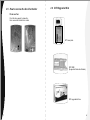
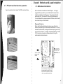
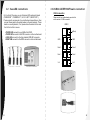
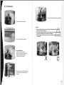
1
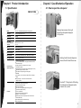
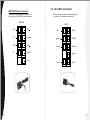
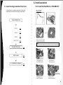
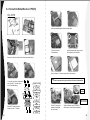
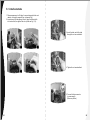
User Manual
VB5001SNA
C 2005 Thermaltake Technology Co.,Ltd. All Rights Reserved.
www.thermaltake.com
Contents
Chapter1 Product Introduction
1.1 Specification
1
Chapter2 Case Mechanical Operation
2.1 How to open the side panel
2.2 Installing 5.25" Device
2.3 Installing 3.5" HDD
2.4 Installing 3.5" Device to Drive Tray
With Power Button
2.5 How to Remove the Fan & Fan Holder
2.6 BTX Upgraded Kits
2.7 PCI slot tool-free function operation
2
3
4
5
7
8
9
Chapter3 Motherboard & Leads Installation
3.1 Motherboard Installation
3.2 Case LED connections
3.3 USB2.0 & IEEE1394 Firewire connection
3.4 Ear & Mic Connections
10
11
12
14
Chapter4 Power Supply
4.1 Silent PurepowerTM power supply (optional)
15
Chapter5 Liquid Cooling Installation
5.1 Liquid Cooling Installation Flow Chart
5.2 Install waterblock
5.2.1 Install the WaterBlock on CPU(AMD K7)
5.2.2 Clip the WaterBlock on CPU(AMD K8)
5.2.3 Install the WaterBlock on CPU(P4)
5.2.4 Install the WaterBlock on CPU(LGA775)
5.3 Install watertube
5.4 Fill Coolant
17
18
19
21
23
25
27
Chapter1 Product Introduction
1.1 Specification
Chapter2 Case Mechanical Operation
2.1 How to open the side panel
VB5001SNA
Model
Tai-Chi --- VB5001SNA (with liquid cooling system)
Case Type
Liquid Cooling System Case
Net Weight
20.5 Kg
Dimension
600 x 263 x 546 mm (H*W*D)
Drive Bays
-Front Accessible
-Internal
11
Up to 10 x 5.25" , 1 x 3.5"
3 x 3.5"
Material
Aluminum Extrusion
color
Silver & Black
Expansion Slots
7
Motherboards
Micro ATX, ATX, Extend ATX, BTX, Micro BTX, Pico BTX
BTX upgraded kits
SRM / Rear plate (option)
Liquid Cooling
system application
Liquid Cooling system
4 in 1 universal waterblock: All copper base with blue LED,
and universal clips
Cooling system: Dual 1300rpm 12 cm fan with
performance radiator
12V liquid pump: Powerful DC 12V liquid pump (84 L /Hour)
Liquid Tank: Easy to refill the coolant
Water tubes: Transparent green water pipes
Remove two screws on the right
side of the side panel displayed
in the picture.
Holding the left side of side panel,
remove the left side of the screw.
Case fan
Front (intake) : 120 x 120 x25 mm blue LED fan, 1300rpm,
17dBA,
Rear (Exhaust) : 120 x 120 x25 mm blue LED fan,
1300rpm 17dBA.
Features
1
All aluminum extrusion built chassis
Compact and stylish chassis
BTX & ATX compatible
Better choice for upgrading liquid cooling system
Hydraulic side panel opening
Tool-free installation
Optimize internal space and airflow
Support to 11 5.25" drive bays
Relocate-able front control panel (Power, Reset switch,
HDD & PWR LEDs)
Removable aluminum motherboard tray
Easy Lifting Handles
Caution!!!! The hydraulic lift holding
the side panel will pop open when
screw is not in place.
2
2.2 Installing 5.25" Device
2.3 Installing 3.5" HDD ( For 12cm Fan Cage )
Remove the drive bay cover from the selected position,
then insert the device into the 5.25" drive bay
Remove thumb screws at both side and remove the fan cage
Insert HDD by sliding HDD into
the 12 cm fan cage.
Secure HDD by tightening screws
to HDD
Finish installation
Insert back the fan cage and tighten
with thumb screws at both side.
3
4
2.4 Installing 3.5" Device to Drive Tray With
Power Button
Remove and slide drive bay out-ward to remove.
Place cover back to drive
tray to its original position.
Insert 3.5" device and
secure device with screw.
Insert the device tray pictured above and secure the device
tray by thumb screws.
Squeeze both top and bottom
portion of drive tray cover picture
to the left to remove cover.
Remove mesh from cover
Drive tray with Power
Button can be placed
at any drive bay
desired.
5
6
2.5 How to remove the fan & fan holder
2.6 BTX Upgraded Kits
12 cm rear fan
Push fan clip upward to loose fan,
then remove fan holder from inside
BTX rear plate
BTX SRM
(Supported Retention Module)
BTX upgraded kit box
7
8
Chapter3 Motherboard & Leads Installation
2.7 PCI slot tool-free function operation
Open the plastic clip then take off the PCI bracket as follow.
3.1 Motherboard Installation
Each motherboard has different standoff layout. It is highly
suggested that you refer to your motherboard's manual when
installing motherboard into the case. The case is applicable
with Extend-ATX Standard ATX, Micro ATX motherboards.
Your motherboard may require a special I/O Panel, which should
be included with your motherboard.
Placement Direction:
When installing the motherboard, make sure you follow the
direction provided by your motherboard manufacturer. On most
standard motherboards, the edge with external ports goes to the
rear part of the chassis. It is highly recommended that you install
CPU, heat sink and modular components before fixing the
motherboard inside the chassis.
= the locations of
the screw holes. Note
these locations and
place included
standoffs on the chassis
first.
This side towards
the rear of the
chassis
Above illustration is a sample of what
the motherboard's layout. For more
detail screw hole placement, please
refer to your motherboard manual.
9
10
3.2 Case LED connections
On the front of the case, you can find some LEDs and switch leads
(POWER SW*1, POWER LED*1, H.D.D. LED*1, RESET SW*1).
Please consult user manual of your motherboard manufacturer, then
connect these leads to the panel header on the motherboard. These
leads are usually labeled; if not, please trace them back to the case
front to find out their source.
- POWER LED connects to your M/B at the PLED.
- POWER SW connects to the PWR connector on the motherboard.
- H.D.D LED connects to the 2-pin labeled HDD LED connector.
- RESET SW connects to the RSW connector on the motherboard.
11
3.3 USB2.0 & IEEE1394 Firewire connection
USB connection
Please consult your motherboard manual to find
out the section of "USB connection".
USB2.0
Brank)
GND1
GND2
Data+1
Data+2
Data-1
Data-2
Vcc1
Vcc 2
12
3.4 Ear & MIC connections
IEEE1394 Firewire connection
Please consult your motherboard manual to find
out the section of "IEEE1394 Firewire connection".
Please consult your motherboard manual to find out
the section of "front panel audio connector".
IEEE1394a
TPA+
VG
TPB+
VP
AUDIO
TPA
Brank)
TPB
MIC IN
Brank
MIC BIAS
Return K
Spekout R
Brank)
GND
13
GND
Brank)
Return L
Splout L
14
Chapter4 Power Supply
4.1 Silent PurepowerTM power supply (optional)
The Thermaltake Silent TM Purepower specification meets Intel
Pentium 4 and AMD K7; it offers plenty of functions, which mainly
include:
1.Automatic Fan Speed Control: The Silent Purepower TM power
supply can detect the inside heat and automatically adjust the fan
speed to provide adequate airflow.
2.Ultra Silent:Ball bearing fans with high reliability and super low
acoustic noise under all load condition.
The functions can assure the Silent Purepower TM meet the balance in
noise control and heat exhausted. The Silent PurepowerTM provides
complete protection function as follow:
1.Over thermal protection at 100 C-105 C
2.Short circuit protection on all output.
3.Over voltage protection / Under voltage protection.
4.Over current protection.
Chapter5
Liquid Cooling Installation
Besides, Thermaltake enables the quality assurance of the Silent
Purepower TM: 100% Hi-POT and ATE Function Test, 100% Burn-In and
AC Input cycled on/off under high temperature condition. Furthermore,
it has been approved by UL, CSA, TUV, VDE, NODIC, CB, FCC, CE,
CNS.
There are three main products of Thermaltake PSU, it is divided into
standard, VR and specialty power supply unit. Please refer to
http://www.thermaltake.com/purepower/main.htm
15
16
5.2 Install waterblock
5.1 Liquid Cooling Installation Flow Chart
In order to ensure convenience and safety, following the
installation procedure below is strongly recommended.
5.2.1 Install the WaterBlock on CPU(AMD K7)
Clip for K7
1.Install Waterblock
K7 CPU
P.18
K8 CPU
P.19
P4 CPU
P.21
LGA775 CPU
P.23
>>
Apply a thin layer of thermal
compound on the processor.
Note :
Too much compound may decrease the performance of waterblock.
2.Install Water tube
P.25
1
3.Fill Coolant
4. Installation Complete
2
P.27
Place waterblock on
top of CPU as shown.
Secure the short
side of the clip first
P.28
3
4
Plug the 3-pin
power connector
Place waterblock on
top of CPU as shown.
17
Complete the CPU
waterblock installation
18
5.2.2 Clip the WaterBlock on CPU(AMD K8)
7
6
Install for K8
Insert the screws through the holes as shown above.
8
1
9
2
Insert the washers and copper columns
then tighten the nut as shown.
Turn to the front side
of motherboard.
Remove the retention module and back plate from
motherboard first.
3
10
11
4
Apply a thin layer of thermal
compound on the processor.
Turn to back side of motherboard
and align the "H" insulator to the
2 holes pointed out.
5
copper column
Note :
Too much compound may decrease the performance of waterblock.
"H" Plate
copper column
washer
12
13
2 copper columns
M/B
Insulator
Plug in the 3-pin
power connector
Mylar
Place the "H" metal back plate
directly over the " H" insulator.
"H" Plate
screw
19
Apply force to the "H" plate
and tighten the nuts to
each screws.
Tighten additional copper columns to
each screws to ensure proper installation.
20
5.2.3 Install the WaterBlock on CPU(P4)
6
7
Clip for P4
Insert the screws through the holes as shown above.
8
1
9
2
Insert the washers and copper columns
then tighten the nuts as shown.
Turn to the front side
Of motherboard.
Remove the retention module from bracket motherboard first.
3
10
11
4
Apply a thin layer of thermal compound on the processor.
Turn to the back side of motherboard
and align the "H" insulator to the
4 holes indicated above.
Note :
Too much compound may decrease the performance of waterblock.
copper column
"H" Plate
5
copper column
12
13
4 copper
columns
washer
M/B
Plug in the 3-pin
power connector
Insulator
Place the "H" metal back plate
directly over the " H" insulator.
Mylar
"H" Plate
Put the "H" plate on the
waterblock and tighten
the nuts to each
Tighten additional copper columns for
each screw to ensure proper installation.
screw
21
22
5.2.4 Install the WaterBlock on CPU(LGA775)
4
5
Clip for P4LGA775
Insert the screws through the holes as shown.
6
1
7
2
Insert the washers and copper columns
then tighten the nuts as shown.
Turn to the front side
of the motherboard.
8
9
Turn to the back side of motherboard and align the "H" insulator to
the 4 holes indicated.
copper column
3
"H" Plate
copper column
washer
Apply a thin layer of included thermal compound on the processor.
Note :
Too much compound may decrease the performance of waterblock.
M/B
Insulator
Place the "H" metal back plate
directly over the " H" insulator.
10
Mylar
11
4 copper
columns
"H" Plate
screw
Plug in the 3-pin
power connector
Put the "H" plate on the
waterblock and tighten
the nuts to each
23
Tighten additional copper columns to each screw
to ensure proper installation.
24
5.3 Install watertube
1. Please measure and cut 2 tubes for connecting water-block and
radiator, its length is around 40 cm. (shown as fig1)
2. Insert one end the tube through the nut, plug the tubes in both
inlet and outlet, then tighten the nuts. (shown as fig 2, 3, 4)
3. Insert the other end of the tube
through the nut on waterblock.
4. Tighten the nut on waterblock.
1
5. Connect the 4pin connector
to power supply.
(Shown as picture)
25
26
5.4 Fill Coolant
5. Close the pump.Installation complete.
1. Fill the tank up with coolant.
Note:
1.Please make sure there is no air inside the tube when you first
time power on the system.
2.If there are bubbles within the tube when operating. You may tap
the tubes a few times to remove the bubbles.
3. Please make sure the water tube is not bending when close the
side panel.
2. Turn on the PC power switch.
3. Important Notice:
Liquid level will decrease
when you power on the system,
please keep filling coolant
until the tank is filled up.
X
4. Please make sure liquid is flowing
continously and smoothly within
the tube.
27
28