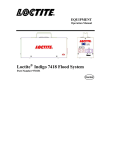
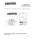
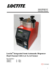
1
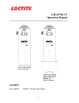
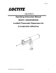
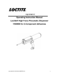
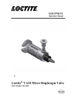
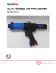
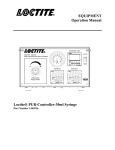
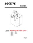
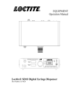
EQUIPMENT Operation Manual 7411-S UV Flood System Item No. 98413 Material No. 630560 UV Warning: UV Energy is transmitted from this unit. Protective eyewear equipped with side shields are required that meet ANSI Z80.3 & Z87.1 Certification. Observe safety precautions as listed in the equipment manual. 7411-S UV Flood System On Off Hour Meter Loctite 7411-S UV Flood System Item Number 98413 Material Number 630560 Table of Contents 1 Please Observe The Following 1.1 Emphasized Sections 1.2 For Your Safety 1.3 Items Supplied 2 Description 2.1 Operation 2.2 System Components 3 3 3 3 4 4 4 3 Technical Data 4 3.1 Specifications 4 4 Installation 4.1 Unpacking and Inspection 4.2 Installation and Startup 5 Operation 5.1 Controls and Operation 5 5 5 6 6 6 Troubleshooting 7 7 Care and Maintenance 8 7.1 Maintenance 8 8 Documentation 9 8.1 Wiring Diagram 8.2 Spare Parts List 9 9 9 Warranty 10 1 Please Observe The Following 1.1 Emphasized Sections Warning! Refers to safety regulations and requires safety measures that protect the operator or other persons from injury or danger to life. Caution! Emphasizes what must be done or avoided so that the unit or other property is not damaged. Notice: Gives recommendations for better handling of the unit during operation or adjustment as well as for service activities. 1.2 For Your Safety IMPORTANT! DO NOT OPERATE THE UNIT BEFORE READING THIS SECTION. The Loctite® 7411-S UV Flood System is a source of long wavelength ultraviolet light used to cure light sensitive products. The system incorporates UV shielding and a non-reflective work surface. It is safe when installed and used properly. The following guidelines should be followed at all times to ensure protection from the ultraviolet light. 1. UV protective glasses with side shields should be worn when working with and around the lamp system. Glasses should meet ANSI Z87.1 certification. 2. Potentially exposed skin should be covered. Long sleeves and protective gloves should be worn when placing and removing parts from under the lamp. 3. Never look directly at the output from the lamp or directly into the lamp/reflector. 3. Removing the glass filter from the lamp housing may speed the curing of some products, however, this will also speed injury to eyes and unprotected skin. Appropriate safety precautions must be taken if the filter is removed. UV safety is the responsibility of the user, especially when operating the Loctite® 7411-S in a non-standard configuration. When in doubt about UV safety, consult a Loctite® technical specialist at 1-800-LOCTITE (562-8483). 1.3 Items supplied UV Power Supply Reflector Housing with Flexible UV Curtain Shield attached Height adjustment for Reflector Housing Power Cord UV Protective Eye ware Cotton Gloves Operators Manual Filter Glass (boxed) Reusable Shipping Box and Foam Packaging Carefully unpack the Loctite® 7411-S and examine the items contained in the carton. Inspect the unit for any damage that might have occurred in transit. If such damage has occurred, notify the carrier immediately. Claims for damage must be made by the consignee to the carrier and should be reported to the manufacturer. 2 Description 2.1 Operation The Loctite® 7411-S UV Flood System is designed for use in a wide range of bonding, potting, tacking and sealing applications. Because of its reliability and simplicity, it is well suited for most production operations. The system irradiates medium power, long wave, ultraviolet light over an 8 x 8 inch work area. An optional visible light enhanced lamp is also available for use with Loctite® visible light curing products (refer to spare parts list). The major components of the system include a power supply, reflector housing with lamp, stand and work surface, flexible UV shielding, connector cable, and power cord. The lamp housing and stand may be placed on top of the power supply to conserve space. The work surface is covered by a special silicone rubber mat, which resists UV deterioration and chemical attack. Over time, it may soften and need replacement. 2 Description (continued) 2.2 System Components DO NOT LIFT UNIT USING THIS HANDLE 7411-S UV Flood System Item No. 98413 Material No. 630560 UV Warning: UV Energy is transmitted from this unit. Protective eyewear equipped with side shields are required that meet ANSI Z80.3 & Z87.1 Certification. Observe safety precautions as listed in the equipment manual. LAMP HEAD RELEASE AND LOCK HANDLE LAMP P/N 97246 UV PROTECTIVE CURTAIN P/N 984927 WORK SURFACE PAD P/N 984967 HOUR METER RESET 7411-S UV Flood System On Off Hour Meter FUSE: BUSSMAN GBD-10 10 AMP, 5MM X 20MM FAST ACTING LAMP HOURS POWER SWITCH 3 Technical Data 3.1 Specifications Loctite® Model: Loctite® Item Number: Loctite® Material Number: Electrical Power Required: Lamp Type: (visible and UV enhanced) Power Supply Dimensions L x W x H (inches): Power Supply Weight: Irradiator / Lamp Housing Dimensions: L x W x H (inches): Irraditor / Lamp Housing Weight: Total Weight, (including stand): Range of travel from work surface to irradiator base: 7411-S UV Flood System 98413 630560 120 VAC, 60 Hz single phase, 8 Amps 400 Watt Metal Halide 11.25" x 12" x 5" 17.4 Pounds 11" x 11" x 8.5" 20 Pounds 37.4 Pounds 0 to 12 inches 4 Installation 4.1 Unpacking and Inspection Carefully remove the system from its shipping carton and inspect it for any signs of damage. Any damage should be reported immediately to the carrier. Refer to the list of supplied parts, and compare to the contents. Report any missing parts promptly to the Loctite® customer service department at 1-800-LOCTITE (562-8483). 4.2 Installation and Start-up The Loctite® 7411-S UV Flood System will arrive completely assembled, except for the filter glass. Filter glass is not installed to prevent breakage during shipments. To install filter glass, remove lamp head from post. Place on a work surface with reflector facing up. Install glass and replace lamp head on post. All that is required is to install the filter glass and plug in the power supply to the lamp connector cable and the power cord at the rear of the power supply. The system should be positioned to allow at least 6 inches clearance at the power supply and lamp housing fans for adequate ventilation. Be sure to wear UV protective glasses at all times while operating the system. A pair is supplied with the unit. To energize the system, turn the power switch on and allow 5 minutes for the lamp to reach full power. To maximize lamp life, the unit should be kept under power without frequent on / off cycling. It is suggested that the lamp remain on during work breaks. The lamp should be allowed to operate a minimum of 15 minutes before turning the system off. Once off, a minimum of 5 minutes cooling time is required before restarting. The position of the reflector / lamp housing is adjustable up or down to control the amount of UV light irradiated onto the part and product. The position and exposure time required to complete the curing process must be determined initially. Be sure that the flexible UV shielding is in place at all times when the system is in use. 5 Operation 5.1 Controls and Operation The Loctite® 7411-S system is easy to use and requires only that the power be switched on to operate. An hour meter is located on the front of the power supply to keep track of the operating time accumulated on the lamp. The meter should be reset each time a new lamp is installed. The reset button is located to the rear of the power supply. 5 Operation (continued) The amount of UV energy delivered to the part is controlled by the distance between the bond area and the lamp / irradiator, and the time of exposure. The time required for curing can be minimized by setting the bottom edge of the irradiator housing one to two inches above the bond area. Increasing the distance will result in increased cure times. The area of the part to be cured should be centered underneath the irradiator / lamp assembly. UV lamps also emit heat energy that is usually insignificant, however, if heat sensitive parts are being processed, a sample part should be tested by exposing it to a cure cycle. It may be necessary to move the part farther from the lamp and increase the cure time. The UV power should be monitored regularly using a radiometer. A reading should be taken when the new lamp is first ignited so subsequent changes in the UV output can be identified. Measurements should be made using the same type of radiometer and preferably the exact same instrument, if possible. The Loctite® UV A/B Light Radiometer Dosimeter P/N: 1390323 can be used to monitor performance. In addition to the system configuration of lamp base attached to power supply, the system can be run as a power supply separate from the lamp base assembly. A six foot extension cable is also available from Loctite® (part # 985022). With the lamp turned off, the lamp head and base can be taken off the power supply and operated at bench level by simply removing the four screws. It is recommended that the four screws be stored in the mating holes on the power supply. 6 Troubleshooting Symptom Corrective Action/Possible Cause Lamp does not light, power switch does not light, and fans do not start. •Make sure the system is plugged in. •Check the fuse in the power cord receptacle. Lamp does not light, power switch lights, fans are running. •Make sure that the lamp is on. •Lamp is at end of its life. •Check that the connector cord is properly installed at both ends. UV Output is low. (Radiometer Reading) •Glass filter needs cleaning. •Lamp is at end of its life. •Lamp needs to be cleaned. •Reflector needs to be cleaned. •Check radiometer accuracy, calibration. Poor or Slow Cure results. •UV output is low (see above). •Product is not compatible with the lamp type. •Position lamp closer to the part. 7 Care and Maintenance 7.1 For Your Safety Unplug the power cord from the wall outlet and disconnect it from unit before any maintenance is attempted. Glass and Reflector Clean the glass every two months or as required. Product vapors can condense on the glass over time, forming a film that can significantly reduce the transmittance of UV light to the parts. Clean the aluminum reflector every four months or as required. The reflector is accessed by removing the filter glass. Use Isopropyl alcohol and a clean, soft cloth to clean both the reflector and glass. Lamp and Sockets Inspect the lamp sockets when installing a new lamp and replace if corroded. Heat generated by poor connections can reduce lamp life. Lamp should be replaced as required. It is recommended that the lamp output be monitored regularly with a radiometer to insure that the product is being completely cured. The Loctite® UV A/B Light Radiometer Dosimeter P/N: 1390323 can be used to monitor performance. As an alternative, regular inspection of the cured product may provide an indirect and less accurate measure of lamp function. If a radiometer is not used to track lamp life, the lamp should be replaced at least after every 1,000 hours of operation. To remove the lamp, first remove the lamp head assembly and place on a work surface with the filter glass facing up. Remove the four screws that hold the filter glass and reflector assembly in place. Remove the filter glass from the reflector housing. Do this only after the lamp has cooled and the system is unplugged. When handling the filter glass and the lamp, use cotton gloves or a soft cloth. Grasp the ends of the lamp, near the socket, to remove it. Inspect the new quartz lamp envelope for cleanliness. If necessary, clean the lamp with isopropyl alcohol and a soft cloth. Insert the new lamp into the sockets, grasping it only at the ends. Reinstall the filter glass and the four screws. If the work surface becomes coated with adhesive or cracks, a new pad can be installed by removing the old pad and carefully attaching the new adhesivebacked pad. The part number for the work surface pad is # 984967. 8 Documentation 8.1 Wiring Diagram 8.2 Spare Parts List Item Part Number UV Enhanced Metal Halide Lamp Visible Light Enhanced Metal Halide Lamp Glass Filter Kit UV Safety Glasses Protective Curtain Adhesive-Backed Work Surface Pad 6 Foot Power Supply — Lamp Extension Cable Loctite® 7411-S Manual Lamp Ignitor Lamp Holder Socket Reflector Cooling Fan Illuminated Switch 97246 983050 985021 97210 984927 984967 985022 988165 982981 980872 984932 984941 984950 9 Warranty Henkel expressly warrants that all products referred to in this Instruction Manual for the Loctite® 7411-S UV Flood System Item No. 98413 Material No. 630560 (hereafter called “Products”) shall be free from defects in materials and workmanship. Liability for Henkel shall be limited, as its option, to replacing those Products which are shown to be defective in either materials or workmanship or to credit the purchaser the amount of the purchase price thereof (plus freight and insurance charges paid therefor by the user). The purchaser’s sole and exclusive remedy for breach of warranty shall be such replacement or credit. A claim of defect in materials or workmanship in any Products shall be allowed only when it is submitted in writing within one month after discovery of the defect or after the time the defect should reasonably have been discovered and in any event, within (12) months after the delivery of the Products to the purchaser. This warranty does not apply to perishable items, such as UV lamp, work surface pad, fuses, etc. No such claim shall be allowed in respect of products which have been neglected or improperly stored, transported, handled, installed, connected, operated, used, or maintained. In the event of unauthorized modification of the Products including, where products, parts or attachments for use in connection with the Products are available from Henkel, the use of products, parts or attachments which are not manufactured by Henkel, no claim shall be allowed. No Products shall be returned to Henkel for any reason without prior written approval from Henkel. Products shall be returned freight prepaid, in accordance with instructions from Henkel. NO WARRANTY IS EXTENDED TO ANY EQUIPMENT WHICH HAS BEEN ALTERED, MISUSED, NEGLECTED, OR DAMAGED BY ACCIDENT. EXCEPT FOR THE EXPRESS WARRANTY CONTAINED IN THIS SECTION, HENKEL MAKES NO WARRANTY OF ANY KIND WHATSOEVER, EXPRESS OR IMPLIED, WITH RESPECT TO THE PRODUCTS. ALL WARRANTIES OF MERCHANTABILITY, FITNESS FOR A PARTICULAR PURPOSE, AND OTHER WARRANTIES OF WHATEVER KIND (INCLUDING AGAINST PATENT OR TRADEMARK INFRINGEMENT) ARE HEREBY DISCLAIMED BY HENKEL AND WAIVED BY THE PURCHASER. THIS SECTION SETS FORTH EXCLUSIVELY ALL OF LIABILITY FOR HENKEL TO THE PURCHASER IN CONTRACT, IN TORT OR OTHERWISE IN THE EVENT OF DEFECTIVE PRODUCTS. WITHOUT LIMITATION OF THE FOREGOING, TO THE FULLEST EXTENT POSSIBLE UNDER APPLICABLE LAWS, HENKEL EXPRESSLY DISCLAIMS ANY LIABILITY WHATSOEVER FOR ANY DAMAGES INCURRED DIRECTLY OR INDIRECTLY IN CONNECTION WITH THE SALE OR USE OF, OR OTHERWISE IN CONNECTION WITH, THE PRODUCTS, INCLUDING, WITHOUT LIMITATION, LOSS OF PROFITS AND SPECIAL, INDIRECT OR CONSEQUENTIAL DAMAGES, WHETHER CAUSED BY NEGLIGENCE FROM HENKEL OR OTHERWISE. Henkel Corporation One Henkel Way Rocky Hill, CT 06067-3910 Henkel Canada Corporation 2515 Meadowpine Boulevard Mississauga, Ontario L5N 6C3 Canada Henkel Capital, S.A. de C.V. Calzada de la Viga s/n Fracc. Los Laureles Loc. Tulpetlac, C.P. 55090 Ecatepac de Morelos, Edo. de México Henkel Corporation Automotive / Metals HQ 32100 Stephenson Hwy. Madison Heights, MI 48071 Henkel Ltda. Rua Karl Huller, 136 –Jd. Canhema 09941-410 Diadema/SP, Brazil www.loctite.com Loctite is a trademark of Henkel Corporation, U.S.A. © Copyright 2004. Henkel Corporation All rights reserved. Data in this operation manual is subject to change without notice. Manual P/N: 988165, Rev D, Date: 04/15/2013