1
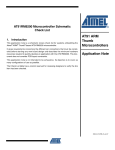
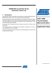
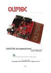
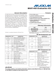
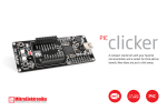
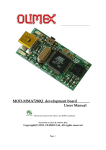
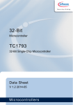
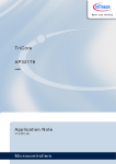
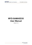
AT91SAM7S Microcontroller Series Schematic
Check List
1. Introduction
This application note is a schematic review check list for systems embedding Atmel’s
AT91SAM7S series of ARM® Thumb®-based microcontrollers.
It gives requirements concerning the different pin connections that must be considered before starting any new board design and describes the minimum hardware
resources required to quickly develop an application with the AT91SAM7S Series. It
does not consider PCB layout constraints.
AT91 ARM
Thumb-based
Microcontrollers
Application Note
It also gives advice regarding low-power design constraints to minimize power
consumption.
This application note is not intended to be exhaustive. Its objective is to cover as
many configurations of use as possible.
The Check List table has a column reserved for reviewing designers to verify the line
item has been checked.
6258C–ATARM–13-Feb-07
2. Associated Documentation
Before going further into this application note, it is strongly recommended to check the latest
documents for the AT91SAM7S Series Microcontrollers on Atmel’s Web site.
Table 2-1 gives the associated documentation needed to support full understanding of this application note.
Table 2-1.
2
Associated Documentation
Information
Document Title
User Manual
Electrical/Mechanical Characteristics
Ordering Information
Errata
AT91SAM7S Series Product Datasheet
Internal architecture of processor
ARM/Thumb instruction sets
Embedded in-circuit-emulator
ARM7TDMI® Datasheet
Evaluation Kit User Guide
AT91SAM7S-EK Evaluation Board User Guide
Application Note
6258C–ATARM–13-Feb-07
Application Note
3. Schematic Check List
3.3V Single Power Supply Strategy (On-chip Voltage Regulator Used)
To reduce power consumption, voltage regulator can be put in standby mode.
100nF
VDDFLASH
100nF
VDDIO
DC/DC Converter
GND
VDDIN
3.3V
4.7µF
100nF
GND
Voltage
Regulator
2.2µF
100nF
VDDOUT
100nF
VDDCORE
100nF
VDDPLL
GND
3.3V Single Power Supply Schematic Example:(1)
On-chip Voltage regulator is used - Power Supply on VDDIO: 3.3V
!
Signal Name
Recommended Pin Connection
Description
Powers on-chip voltage regulator and ADC.
VDDIN
3.0V to 3.6V
Decoupling/Filtering capacitors
(100 nF and 4.7 µF)(1)(2)
Decoupling/Filtering capacitors must be added to improve
startup stability and reduce source voltage drop.
VVDDIN SLOPE (TSLOPE) must be superior or equal to
6V/ms.
VDDOUT
Decoupling/Filtering capacitors
(100 nF and 2.2 µF)(1)(2)
VDDIO
3.0V to 3.6V
or
1.65 to 1.95V
Decoupling capacitor (100 nF)(1)(2)
Output of the on-chip 1.8V voltage regulator.
Decoupling/Filtering capacitors must be added to
guarantee 1.8V stability
Powers I/O lines and USB transceivers
Dual voltage range supported.
Note that supplying less than 3.0V to VDDIO prevents any
use of the USB transceivers.
3
6258C–ATARM–13-Feb-07
!
Signal Name
Recommended Pin Connection
Description
VDDFLASH
3.0V to 3.6V
Decoupling capacitor (100 nF)(1)(2)
Powers Flash (charge pump).
VDDCORE
1.65 to 1.95V
Can be connected directly to VDDOUT pin.
Decoupling capacitor (100 nF)(1)(2)
Powers device and flash logic, on-chip RC.
VDDPLL
1.65 to 1.95V
Can be connected directly to VDDOUT pin.
Decoupling capacitor (100 nF)(1)(2)
Powers the main oscillator and the PLL.
Ground
No separate ground pins are provided for the different
power supplies.
Only GND pins are provided and should be connected as
shortly as possible to the system ground plane.
GND
4
Application Note
6258C–ATARM–13-Feb-07
Application Note
3.3V and 1.8V Dual Power Supply Strategy (On-chip Voltage Regulator NOT Used and ADC Used)
To reduce power consumption, voltage regulator can be put in standby mode.
100nF
VDDFLASH
100nF
VDDIO
DC/DC Converter
GND
VDDIN
3.3V
4.7µF
100nF
GND
2.2µF
100nF
VDDOUT
GND
100nF
VDDPLL
DC/DC Converter
GND
VDDCORE
1.8V
2.2µF
100nF
GND
3.3V and 1.8V Dual Power Supply Schematic Example:(1)
On-chip Voltage regulator is not used - ADC is used - Power Supply on VDDIO: 3.3V
!
Signal Name
Recommended Pin Connection
Description
VDDIN
3.0V to 3.6V
Decoupling/Filtering capacitors
(100 nF and 4.7 µF)(1)(2)
Powers ADC.
Decoupling/Filtering capacitors must be added to improve
startup stability and reduce source voltage drop.
VDDOUT
Decoupling/Filtering capacitors
(100 nF and 2.2 µF)(1)(2)
Output of the on-chip 1.8V voltage regulator.
Decoupling/Filtering capacitors must be added to prevent
on-chip voltage regulator oscillations.
VDDIO
3.0V to 3.6V
or
1.65 to 1.95V
Decoupling capacitor (100 nF)(1)(2)
Powers I/O lines and USB transceivers
Dual voltage range supported.
Note that supplying less than 3.0V to VDDIO prevents any
use of the USB transceivers.
5
6258C–ATARM–13-Feb-07
!
Signal Name
Recommended Pin Connection
Description
VDDFLASH
3.0V to 3.6V
Decoupling capacitor (100 nF)(1)(2)
Powers Flash.
VVDDFLASH must always be superior or equal to
VVDDCORE.
Powers device logic, on-chip RC and Flash.
VDDCORE
1.65 to 1.95V
Decoupling/Filtering capacitors
(100 nF and 2.2 µF)(1)(2)
Decoupling/Filtering capacitors must be added to improve
startup stability and reduce source voltage drop.
VVDDCORE SLOPE (TSLOPE) must be superior or equal to
6V/ms.
VDDPLL
1.65 to 1.95V
Decoupling capacitor (100 nF)(1)(2)
Powers the main oscillator and the PLL.
Ground
No separate ground pins are provided for the different
power supplies.
Only GND pins are provided and should be connected as
shortly as possible to the system ground plane.
GND
6
Application Note
6258C–ATARM–13-Feb-07
Application Note
3.3V and 1.8V Dual Power Supply Strategy (On-chip Voltage Regulator and ADC NOT Used)
100nF
VDDFLASH
DC/DC Converter
GND
VDDIO
3.3V
4.7µF
100nF
GND
VDDIN
GND
NC
VDDOUT
100nF
VDDPLL
DC/DC Converter
GND
VDDCORE
1.8V
2.2µF
100nF
GND
3.3V and 1.8V Dual Power Supply Schematic Example:(1)
On-chip Voltage regulator is not used - ADC is not used - Power Supply on VDDIO: 3.3V
!
Signal Name
Recommended Pin Connection
Description
VDDIN
Connected to GND.
-
VDDOUT
Can be left unconnected.
Powers I/O lines and USB transceivers
VDDIO
3.0V to 3.6V
or
1.65 to 1.95V
Decoupling/Filtering capacitors
(100 nF and 4.7µF)(1)(2)
Dual voltage range supported.
Decoupling/Filtering capacitors must be added to improve
startup stability and reduce source voltage drop.
Note that supplying less than 3.0V to VDDIO prevents any
use of the USB transceivers.
VDDFLASH
3.0V to 3.6V
Decoupling capacitor (100 nF)(1)(2)
Powers Flash.
VVDDFLASH must always be superior or equal to
VVDDCORE.
7
6258C–ATARM–13-Feb-07
!
Signal Name
Recommended Pin Connection
Description
Powers device logic, on-chip RC and Flash.
VDDCORE
1.65 to 1.95V
Decoupling/Filtering capacitors
(100 nF and 2.2 µF)(1)(2)
Decoupling/Filtering capacitors must be added to improve
startup stability and reduce source voltage drop.
VVDDCORE SLOPE (TSLOPE) must be superior or equal to
6V/ms.
VDDPLL
1.65 to 1.95V
Decoupling capacitor (100 nF)(1)(2)
Powers the main oscillator and the PLL.
Ground
No separate ground pins are provided for the different
power supplies.
Only GND pins are provided and should be connected as
shortly as possible to the system ground plane.
GND
8
Application Note
6258C–ATARM–13-Feb-07
Application Note
!
Signal Name
Recommended Pin Connection
Description
Clock, Oscillator and PLL
Internal Equivalent Load Capacitance (CL):
CL = 20 pF
Crystal Load Capacitance to check (CCRYSTAL).
AT91SAM7S
CL
XIN
Crystals between 3 and 20 MHz
XIN
XOUT
Main Oscillator
in
Normal Mode
XOUT
Capacitors on XIN and XOUT
(crystal load capacitance dependant)
1K
GND
8 MHz
CCRYSTAL
1 kOhm resistor on XOUT only required
for crystals with frequencies lower than 8
MHz.
CLEXT
CLEXT
Example: for an 18.432MHz crystal with a load
capacitance of CCRYSTAL = 20 pF, no external capacitors
(CLEXT) are required (CCRYSTAL = CL)
Refer to the electrical specifications of the AT91SAM7S
datasheet.
XIN
XOUT
Main Oscillator
in
Bypass Mode
XIN: external clock source
XOUT: can be left unconnected
1.8V Square wave signal (VDDPLL)
External Clock Source up to 50 MHz
Duty Cycle: 40 to 60%
9
6258C–ATARM–13-Feb-07
!
Signal Name
Recommended Pin Connection
Description
See the Excel spreadsheet:
“ATMEL_PLL_LFT_Filter_CALCULATOR_AT91_xxx.zip”
(available in the software files on the Atmel Web site)
allowing calculation of the best R-C1-C2 component
values for the PLL Loop Back Filter.
PLLRC
Second-order filter
PLL
PLLRC
R
Can be left unconnected if PLL not used.
C2
C1
GND
R, C1 and C2 must be placed as close as possible to the
pins.
10
Application Note
6258C–ATARM–13-Feb-07
Application Note
!
Signal Name
Recommended Pin Connection
Description
ICE and JTAG(3)
TCK
Pull-up (100 kOhm)(1)
No internal pull-up resistor.
TMS
Pull-up (100 kOhm)
(1)
No internal pull-up resistor.
TDI
Pull-up (100 kOhm)(1)
No internal pull-up resistor.
TD0
Floating
-
JTAGSEL
Can be left unconnected for normal
operations.
It is strongly recommended to tie this
pin to GND in harsh(4) environments.
Internal pull-down resistor (15 kOhm).
Must be tied to VVDDIO to enter JTAG
Boundary Scan.
Flash Memory
Can be left unconnected for normal
operations
It is strongly recommended to tie this
pin to GND in harsh(4) environments.
ERASE
Internal pull-down resistor (15 kOhm).
Must be tied to VVDDIO to erase the
General Purpose NVM bits (GPNVMx),
the whole flash content and the security
bit (SECURITY).
Reset/Test
NRST is configured as an output at power up.
NRST
TST(5)
Can be left unconnected
Can be left unconnected for normal
operations
It is strongly recommended to tie this
pin to GND in harsh(4) environments.
NRST is controlled by the Reset Controller (RSTC).
An internal pull-up resistor to VVDDIO (10 kOhm) is
available for User Reset and External Reset control.
Internal pull-down resistor (15 kOhm).
Must be tied to VVDDIO to enter Fast Flash
Programming (FFPI) mode or SAM-BA™
Boot recovery mode(5)
11
6258C–ATARM–13-Feb-07
!
Signal Name
Recommended Pin Connection
Description
PIO
PAx
All PIOs are pulled-up inputs at reset and are 5V -tolerant.
To reduce power consumption if not used, the concerned
PIO can be configured as an output, driven at ‘0’ with
internal pull-up disabled.
Application Dependant
ADC
ADVREF is a pure analog input.
ADVREF
2.6V to VVDDIN.
Decoupling capacitor(s).
To reduce power consumption, if ADC is not used:
connect ADVREF to GND.
AD0 to AD3 are digital pulled-up inputs at reset.
AD4 to AD7 are pure analog inputs.
AD0 to AD7
0V to VADVREF.
To reduce power consumption, if ADC is not used:
connect AD4, AD5, AD6 and AD7 to GND.
USB Device (UDP)
To reduce power consumption, USB Device Built-in Transceivers can be disabled (enabled by default).
No internal pull-up/pull-down resistors..
DDP
Application Dependant.(6)
Typically, 1.5 kOhm resistor to VVDDIO.
To reduce power consumption, if USB Device is not used,
connect DDP to VVDDIO.
No internal pull-down resistor.
DDM
Notes:
Application Dependant.(6)
To reduce power consumption, if USB Device is not used,
connect DDM to GND.
1. These values are given only as a typical example.
2. Decoupling capacitors must be connected as close as possible to the microcontroller and on each concerned pin.
100nF
VDDCORE
100nF
VDDCORE
100nF
VDDCORE
GND
3. It is recommended to establish accessibility to a JTAG connector for debug in any case.
4. In a well-shielded environment subject to low magnetic and electric field interference, the pin may be left unconnected. In
noisy environments, a connection to ground is recommended.
5. See: Test Pin description in I/O Lines Considerations section of the corresponding AT91SAM7S datasheet for more details
on the different conditions to enter FFPI or SAM-BA Boot recovery modes.
6. Example of USB Device connection:
As there is no embedded pull-up, an external circuitry can be added to enable and disable the pull-up.
To prevent over consumption when the host is disconnected, an external pull-down can be added to DDP and DDM.
12
Application Note
6258C–ATARM–13-Feb-07
Application Note
A termination serial resistor (REXT) must be connected to DDP and DDM. A recommended resistor value is defined in the
electrical specifications of the AT91SAM7S datasheet.
.
PIO
5V Bus Monitoring
27K
47K
3V3
PIO
Pullup Control
0: Enable
1: Disable
1.5K
REXT
DDM
2
1
3
Type B 4
Connector
DDP
REXT
330K
330K
13
6258C–ATARM–13-Feb-07
4. AT91SAM Boot Program Hardware Constraints
See the AT91SAM Boot Program section of the AT91SAM7S datasheet for more details on the
boot program.
4.1
SAM-BA Boot
The SAM-BA™ Boot Assistant supports serial communication via the DBGU or the USB Device
Port:
• DBGU Hardware Requirements: 3 to 20 MHz crystal or 1 to 50 MHz external clock.
• USB Device Hardware Requirements:
– 18.432 MHz crystal.
– PA16 dedicated to USB DDP Pull-up. When this PIO is driven low by SAM-BA Boot,
the pull-up must be enabled.
14
Application Note
6258C–ATARM–13-Feb-07
Application Note
Revision History
Change
Request
Ref.
Doc. Rev
Comments
6258A
First issue
6258B
disclaimer added to “Introduction” on page 1.
3254
6258C
Section 3. ”Schematic Check List”, Precisions added to schematics of power supply
strategies. Note added for use in harsh environments. Precisions added to ADC and
descriptions. PA16 use definition in Section 4.1 ”SAM-BA Boot”,
“Clock, Oscillator and PLL” on page 9, schematic updated.
3922
15
6258C–ATARM–13-Feb-07
Atmel Corporation
2325 Orchard Parkway
San Jose, CA 95131, USA
Tel: 1(408) 441-0311
Fax: 1(408) 487-2600
Regional Headquarters
Europe
Atmel Sarl
Route des Arsenaux 41
Case Postale 80
CH-1705 Fribourg
Switzerland
Tel: (41) 26-426-5555
Fax: (41) 26-426-5500
Asia
Room 1219
Chinachem Golden Plaza
77 Mody Road Tsimshatsui
East Kowloon
Hong Kong
Tel: (852) 2721-9778
Fax: (852) 2722-1369
Japan
9F, Tonetsu Shinkawa Bldg.
1-24-8 Shinkawa
Chuo-ku, Tokyo 104-0033
Japan
Tel: (81) 3-3523-3551
Fax: (81) 3-3523-7581
Atmel Operations
Memory
2325 Orchard Parkway
San Jose, CA 95131, USA
Tel: 1(408) 441-0311
Fax: 1(408) 436-4314
RF/Automotive
Theresienstrasse 2
Postfach 3535
74025 Heilbronn, Germany
Tel: (49) 71-31-67-0
Fax: (49) 71-31-67-2340
Microcontrollers
2325 Orchard Parkway
San Jose, CA 95131, USA
Tel: 1(408) 441-0311
Fax: 1(408) 436-4314
La Chantrerie
BP 70602
44306 Nantes Cedex 3, France
Tel: (33) 2-40-18-18-18
Fax: (33) 2-40-18-19-60
1150 East Cheyenne Mtn. Blvd.
Colorado Springs, CO 80906, USA
Tel: 1(719) 576-3300
Fax: 1(719) 540-1759
Biometrics
Avenue de Rochepleine
BP 123
38521 Saint-Egreve Cedex, France
Tel: (33) 4-76-58-47-50
Fax: (33) 4-76-58-47-60
ASIC/ASSP/Smart Cards
Zone Industrielle
13106 Rousset Cedex, France
Tel: (33) 4-42-53-60-00
Fax: (33) 4-42-53-60-01
1150 East Cheyenne Mtn. Blvd.
Colorado Springs, CO 80906, USA
Tel: 1(719) 576-3300
Fax: 1(719) 540-1759
Scottish Enterprise Technology Park
Maxwell Building
East Kilbride G75 0QR, Scotland
Tel: (44) 1355-803-000
Fax: (44) 1355-242-743
Literature Requests
www.atmel.com/literature
Disclaimer: The information in this document is provided in connection with Atmel products. No license, express or implied, by estoppel or otherwise, to any
intellectual property right is granted by this document or in connection with the sale of Atmel products. EXCEPT AS SET FORTH IN ATMEL’S TERMS AND CONDITIONS OF SALE LOCATED ON ATMEL’S WEB SITE, ATMEL ASSUMES NO LIABILITY WHATSOEVER AND DISCLAIMS ANY EXPRESS, IMPLIED OR STATUTORY
WARRANTY RELATING TO ITS PRODUCTS INCLUDING, BUT NOT LIMITED TO, THE IMPLIED WARRANTY OF MERCHANTABILITY, FITNESS FOR A PARTICULAR
PURPOSE, OR NON-INFRINGEMENT. IN NO EVENT SHALL ATMEL BE LIABLE FOR ANY DIRECT, INDIRECT, CONSEQUENTIAL, PUNITIVE, SPECIAL OR INCIDENTAL DAMAGES (INCLUDING, WITHOUT LIMITATION, DAMAGES FOR LOSS OF PROFITS, BUSINESS INTERRUPTION, OR LOSS OF INFORMATION) ARISING OUT
OF THE USE OR INABILITY TO USE THIS DOCUMENT, EVEN IF ATMEL HAS BEEN ADVISED OF THE POSSIBILITY OF SUCH DAMAGES. Atmel makes no
representations or warranties with respect to the accuracy or completeness of the contents of this document and reserves the right to make changes to specifications
and product descriptions at any time without notice. Atmel does not make any commitment to update the information contained herein. Unless specifically provided
otherwise, Atmel products are not suitable for, and shall not be used in, automotive applications. Atmel’s products are not intended, authorized, or warranted for use
as components in applications intended to support or sustain life.
© 2007 Atmel Corporation. All rights reserved. Atmel®, logo and combinations thereof, Everywhere You Are®, DataFlash® and others, are registered
trademarks SAM-BA™ and others are trademarks of Atmel Corporation or its subsidiaries. ARM®, the ARM Powered® logo, Thumb® and ARM7TDMI® are
registered trademarks of ARM Limited. Other terms and product names may be the trademarks of others.
6258C–ATARM–13-Feb-07