1
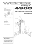
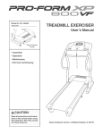
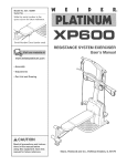
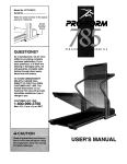
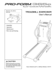
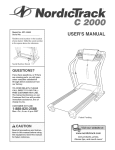
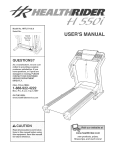
ModelNo.831.295231
Seda[No.
User's Manual
SerialNumber
Decal
* Assembly
Operation
Maintenance
Part List and Drawing
,_ CAUTION
Read all precautions and instructions in this manual before using
this equipment. Save this manual
for future reference.
Sears,
Roebuck
and Co., Hoffman
Estates,
[L 60179
TABLE OF CONTENTS
iMPORTANT
PRECAUTIONS
................................................................
BEFORE YOU BEGIN ......................................................................
ASSEMBLY ...............................................................................
OPERATHON AND ADJUSTMENT ............................................................
HOW TO FOLD AND MOVE THE TREADMHLL ..................................................
TROUBLESHOOTHNG .....................................................................
CONDHTHONHNGGUHDELHNES ...............................................................
ORDERHNG REPLACEMENT PARTS ..................................................
FULL 90 DAY WARRANTY
..........................................................
Note: An EXPLODED DRAWHNG and a PART LHSTare attached in the center of this manual
3
5
6
10
13
15
17
Back Cover
Back Cover
iMPORTANT PRECAUTIONS
WARN ING: Toreduce
ther a.ofburns,
fire,e ectric
ehoc.,
or njury
topersons,
read
the
following
important precautions
and information before operating
1. it is the responsibility
of the owner to ensure
that all users of this treadmill are adequately
informed of all warnings and precautions.
2.
3_
Use the treadmill
only as described.
Place the treadmill on a level surface, with at
least eight feet of clearance behind it and two
feet on each side. Do not place the treadmill
on any surface that Mocks air openings. To
protect the floor or carpet from damage, place
a mat under the treadmill.
4. Keep the treadmill indoors, away from moisture and dust. Do not put the treadmill in a
garage or covered patio, or near water.
5. Do not operate the treadmill where aerosol
products are used or where oxygen is being
administered.
6. Keep children under the age of 12 and pets
away from the treadmill at aH times.
7.
The treadmill should be used only by persons
weighing 250 pounds or lees.
8. Never allow more than one person on the
treadmill at a time.
9,
Wear appropriate exercise clothes when
using the treadmill
Do not wear tooee clothes
that could become caught in the treadmill.
AtHetic support clothes are recommended for
both men and women. Always wear athletic
shoes. Never use the treadmill with bare feet,
wearing only stockings, or in sandals,
10. When connecting the power cord (see page 10),
plug the power cord into a surge suppressor
(not included) and plug the surge suppressor
into a grounded circuit capable of carrying 15
or more ampe. No other appliance should be on
the same circuit. Do not use an extension cord.
11. Use only a single=outlet surge suppressor that
meets aH of the specifications
described on
page 10. To purchase a surge suppressor, see
your local Sears store or call 1-800-366=7278
and order part number 146148, or see your
local electronics store.
the treadmill.
12. Failure to use a properly functioning surge
suppressor couM result in damage to the controi system of the treadmill If the control system is damaged, the walking belt may change
speed, accelerate, or stop unexpectedly,
which may result in a fail and serious injury.
13.
Keep the power cord and the surge suppressor away from heated aurfacee.
14. Never move the walking belt while the power
is turned off. Do not operate the treadmill if
the power cord or plug is damaged, or if the
treadmill is not working properly. (See BEFORE YOU BEGIN on page 5 if the treadmill is
not working properly.)
15. Never start the treadmill whi_e you are stand°
ing on the walking belt. Always hold the
handrails while using the treadmill.
18. The treadmill is capable of high speeds.
Adjust the speed in small increments to avoid
sudden jumps in speed.
17. The pulse sensor is not a medical device.
Various factors, including your movement,
may affect the accuracy of heart rate readings.
"The sensor is intended only as an exercise aid
in determining heart rate trends in general
18. Do not use hand weights at speeds faster
than walking speeds. Using weights and not
holding the handrails may compromise your
ability to maintain your balance. Exercises
using weights should
experienced users.
be attempted
only by
1g. Never leave the treadmill unattended while it
is running. Always remove the key and unplug
the power cord when the treadmill is not in
use.
20. Do not attempt to raise, lower, or move the
treadmill until it is property assembled. (See
ASBEMBLYon
page 6, and HOW TO FOLD
AND MOVE THE TREADMILL on page 13.}
You must be able to safely Hft 45 pounds (20
kg) to raise, lower, or move the treadmill.
21.When
maintenance and adjustment procedures de=
scribed in this manual Never remove the
folding or moving the treadmill, make
sure that the storage latch is fully dosed.
22. inspect and properly
treadmill regularly.
motor hood unJess instructed to do so by an
authorized service representative.
Servicing
other than the procedures in this manual
ahouJd be performed by an authorized service representative
onJy.
tighten all parts of the
23. Never insert any obiect into any opening.
24.DANG ER: AIwoye
unplug
the
power
25, This treadmill
_ WARNING:
is intended for in-home use
only. Do not use this treadmill in a commet=
cial, rental, or institutional setting.
cord immediately after use, before cleaning
the treadmill, and before performing the
Before
beginning
th_s
orany
e,ere_se
program,
consult
your
physician.
Th_s
is especiaJly important for persons over the age of 35 ot persons with pre-existing health problems.
Read aJl instructions before using. Sears assumes no responsibility
for personaJ injury or property
damage sustained by or through the use of this product.
SAVE THESE INSTRUCTIONS
4
BEFORE YOU BEGIN
Thank you for sebcting the new PROFORM ®495 Pi
treadmill The PROFORM 495 Pi treadmHUcombines advanced technobgy with innovative design to heUpyou
get the most from your exercise in the convenience of
your home. And when you're not exercising, the PROFORM 495 Pi treadmHUcan be foUded up, requiring bss
than haft the floor space of other treadmHUs.
For your benefit, read this manual carefully before
using the treadmill, ff you have questions after reading
this manual call 1-800-4-MY-HOME ®(1-800-469-4663).
To heUpus assist you, phase note the product modeU
number and sedaUnumber before calling. The model
number of the treadmill is 831.295231. The serial number can be found on a decal attached to the treadmill
(see the front cover of this manual for the location).
Before reading further, please review the drawing
below and familiarize yourself with the labeled parts,
Fan
Accessory Tray
Key/Clip
Handrail
Upright
Storage Latch
Reset/Off
_d//
Circuit Breaker
Walking Belt
Foot Rail --
__
BACK
Rear RolleH
Cushioned Walking Platform
for maximum exercise comfort
Assemblyrequirestwo persons.SetthetreadmHU
ina clearedareaandremoveaHpackingmateriaUs,
Donot
disposeofthepackingmateriaUs
untilassemMy
is compbted,
Note:Theunderside
ofthetreadmillwalkingbeltiscoatedwithhighoperformance
lubricant,Duringshipping,a
smallamountof lubricantmaybetransferred
tothetopofthewalkingbeltortheshippingcarton,Thisis a normal
conditionanddoesnotaffecttreadmillperformance,
if thereis lubricantontopofthewalkingbelt,simplywipeoff
thelubricantwitha softclothanda mild,nonoabrasive
cleaner,
E
Assembly
requires
the included
rubber mallet _x(_,
allen wrenches
and adjustable
wrench
_ and your own phillips
_
screwdriver
.
For help identifying the assembJy hardware, see the drawings below, if a part is not in the parts bag, first
check to see if it has been pre-assembled, If a part is missing, call toll-free 1-888-533-1333.
Silver Ground
Screw (75)-1
1/2" Screw (48)-10
3/4" Screw (2)-2
1" Tek Screw (39)-6
2" Bolt (64)-2
Wheel Nut (32)-2
Handrail Bolt (37)-4
1, Make sure that the power cord is unplugged.
With the help of another person, carefully raise the
Uprights (69) to the vertical position, insert one of the
Extension Legs (63) into the treadmill as shown, (Note: it
may be helpful to tip the Uprights as you insert the
Extension Leg,) Make sure that the Base Pad (61) is
under the Extension Leg,
insert the other Extension Leg (63) in the same way,
63
61
identify the Right Handrail (72), which has a Uargehob in
the bft side, Feed the Upright Wire (42) into the hob in
the bottom of the Right Handrail and out of the Uargehob
in the side, Note: it may be heUpfuUto use needbnose pliers to pull the Wire Harness out of the hob,
71
Attach the upper end of the Right Handrail (72) with a
Handrail BoUt(37), Do not tighten the Bolt yet,
Attach the upper end of the Left Handrail (71) as described above, Do not tighten the Bolt yet, Note: There
is not a wire harness on the bft side,
With the heUpof another person, carefully bwer the
Uprights (69) as shown, Note: it may be heUpfuUto pUace
one foot on one of the Extension Legs (63) as you tip the
Uprights, Make sure that the Extension Legs remain
in the Uprights.
Align the lower end of the Right Handrail (72) with the
hob in the Extension Leg (63), Attach the Right Handrail
with a Handrail Bolt (87), Attach the lower end of the Left
Handrail (71) in the same manner,
71
37
AttacheachExtensionLeg(63)withtwo1"TekScrews
(39)anda ThickBasePad(57)asshown,Attachthe
towerTekScrew,withoutthe Thick BasePad,first.
4
69
66
64
AttachtwoThickBasePads(57)tothebaseofthe
Uprights(69)withtwo1"TekScrews(39),
AttachthetwoWheeUs
(66)withtwo2"BoUts
(64)and
twoWheeU
Nuts(32)asshown,Donot overtightenthe
Bolts;theWheeUs
shouUd
beabb tospinfreeUy,
/
66
64
WiththeheUp
ofanotherperson,carefullyraisethe
Uprights(69)tothevertbaU
position,
Seestep2,TightenthetwoHandrailBoUts
(37),
.....
_39
Hold the Console Base (47) near the Left Handrail (71),
Attach the end of the ground wire on the Console Base
to the indicated small hob in the Left Handrail with the
Silver Ground Screw (75),
47
Ground
Wire
Small
71
Touch the Right Handrail (72} to discharge any static.
Press the end of the Upright Wire (42) into the socket in the
bottom of the Console Base (47), The connector shouJd
sJide easily into the socket and snap into place, if the
connector does not slide easily and snap into place, turn
the connector and then insert it,
42
8
47
Set the ConsoUeBase (47) on the Right Handrail (72) and
the Left Handrail (71), Attach the ConsoUe Base with four
1/2" Screws (48), Start all four Screws before tightening them; do not overtighten the Screws.
7
47
71
72
48
Press the Upright Wire (42) into the sUotin the underside
of the ConsoUe Base (47) in the indicated area, Cover the
Upright Wire with the Right Grip Hate (36), Be carefut
not to pinch the Upright Wire. Tighten three 1/2"
Screws (48) into the Right Grip Hate and the ConsoUe
Base,
47
Attach the Left Grip Hate (32) over the ground wire and
the other wires with three 1/2" Screws (48), Be careful
not to pinch any of the Wires.
48
48
Attach the Storage Latch (29) and the Latch Spacer (44)
to the UeftUpright (69) with two 3/4" Screw,s (2) as shown,
Do not overtighten the Screws.
10, Make sure that aH parts are properly tightened before you use the treadmill. Note: Extra hardware may
be incUuded, Keep the incUuded allen wrenches in a secure pUace,The large allen wrench is used to adjust the
walking belt (see page 16), To protect the floor or carpet, place a mat under the treadmill,
OPERATmON AND ADJUSTMENT
THE PRE-LUBRmCATED WALKmNG BELT
an equipment-grounding conductor and a grounding
plug, Plug the power cord into a surge suppressor,
and plug the surge suppressor into an appropriate
outlet that is properly installed and grounded in
accordance with aH JocaJ codes and ordinances.
Important: The treadmill is not compatible with
GFCl-equipped outJets.
Your treadmHUfeatures a waUking beUtcoated with highperformance Uubrbant, IMPORTANT: Never apply silicone spray or other substances to the walking
belt or the walking platform. Such substances will
deteriorate the walking belt and cause excessive
wear.
This product is for use on a nominal 120-volt circuit,
and has a grounding plug that looks like the plug illustrated in drawing 1 below, A temporary adapter that
looks like the adapter illustrated in drawing 2 may be
used to connect the surge suppressor to a 2-pole
receptacle as shown in drawing 2 if a properly
grounded outlet is not available,
HOW TO PLUG mNTHE POWER CORD
of the equi pment-grounding
conductor can
result in an increased risk of electric shock.
Check with a qualified electrician or serviceman if you are in doubt as to whether the
product is properly grounded. Do not modify
the plug provided with the product--if
it will
not fit the outlet, have a proper outlet
installed by a qualified electrician.
I
SbGrounded
Your treadmill, like any other type of sophisticated
electronic equipment, can be seriously damaged by
sudden voltage changes in your home's power,
Voltage surges, spikes, and noise interference can
result from weather conditions or from other appliances
being turned on or off, To decrease the possibility of
your treadmill being damaged, always use a surge
suppressor with your treadmill (see drawing 1 at
the right}. To purchase a surge suppressor, see
your Jocal Sears store or call 1-800-366-7278 and
order part number 146148, or see your total electronics store.
Outlet Box
_"-I
--
Surge Suppressor
_<
"-. Grounding Pin
Grounding Pin
_rounded Outlet
Grounding Hug
2
_rounded Outlet Box
Adapter
Use onJy a singJe-ouflet surge suppressor that is
UL 1449 Jisted as a transient voJtage surge suppressor (TVSS). The surge suppressor must have a
UL suppressed voltage rating of 400 voJts or Jess
and a minimum surge dissipation of 450 jouJes.
The surge suppressor must be electrically rated for
120 volts AC and !5 amps. There must be a monitoring light on the surge suppressor to indicate
whether it is functioning properly. FaiJure to use a
properly functioning surge suppressor couJd result
in damage to the controJ system of the treadmill. If
the control system is damaged, the walking belt
may change speed, accelerate, or stop une×pectedty, which may result in a fail and serious injury.
The temporary adapter should be used only until a
properly grounded outlet (drawing 1) can be installed
by a qualified electrician,
This product must be grounded. If it should malfunc°
tion or break down, grounding provides a path of least
resistance for electric current to reduce the risk of ebc°
tric shock, This product is equipped with a cord having
grounded
Metal Screw
_
. _Surge
Suppressor
The greemcolored rigid ear, lug, or the like extending
from the adapter must be connected to a permanent
ground such as a properly grounded outlet box cover,
Whenever the adapter is used it must be held in place
by a metal screw, Some 2-pote receptacle outlet box
covers are not grounded. Contact a quaJified electrician to determine if the outJet box cover is
10
before using an adapter.
CONSOLE DmAGRAM
m
FAT
OALS.
PULSE
TIME
DUSTANOE
SPEED
\
Pube Sensor
Note: if there is a thin sheet
Key
Cli
slide the clip onto the waistband of your clothes,
insert the key into the console, A tone wiii sound and
the three displays wiii light, Test the cJip by carefully
taking a few steps backward until the key is pulled
from the consote. If the key is not pulled from the
console, adjust the position of the clip.
CAUTION: Before
oporot the
ng
console,
read the following
precautions.
o Do not stand on the walking
ing on the power.
belt when turn-
* Always wear the clip (see the drawing
above) while operating the treadmi&
Follow the steps below to operate the console,
Insert the key into the console.
o Adjust the speed in small increments to
avoid sudden jumps in speed.
When the key is inserted, a tone wiii sound and
the three displays wiii light,
o To reduce the possibility of electric shock,
keep the console dry. Avoid spilling liquids
on the console and place onJy a seaJed
water bottJe in the accessory trays.
STEP-BY-STEP
Press the Speed + button to start the walking
belt.
A moment after the button is pressed, the walking
belt will begin to move, Hold the handrails and
begin walking,
CONSOLE OPERATION
Before operating the console, make sure that the
power cord is properly plugged in (see page 10),
in addition, make sure that
the reset/off circuit breaker,
located on the treadmill frame
near the power cord, is in the
reset position,
of pUastb on the consob,
remove the pUastb,
As you exercise, change the speed of the walking
belt as desired by pressing the Speed + and buttons, Each time a button is pressed, the speed
setting wiii change by 0,1 mph; if a button is held
down, the speed setting wiii change in increments
of 0,5 mph, To change the speed setting quickly,
press the Quick Speed buttons, Note: The console can display speed and distance in either
miles or kilometers (see SPEED DISPLAY on
page !2). For simplicity, aH instructions in this
section refer to miles.
Reset
Next, stand on the foot rails of the treadmill, Find the
clip attached to the key (see the drawing above), and
11
To stop the walking belt, press the Stop button,
The Time/%stance display will begin to flash,
change the unit of measurement, When the desired unit of measurement is selected, remove the
key and then reinsert it,
Note: During the first few minutes that the treadmill
is used, inspect the alignment of the walking belt,
and align it if necessary (see page 15),
To reset the displays, press the Stop button, remove the key, and then reinsert the key,
Change the incline of the treadmill
Measure your heart rate if desired.
as desired.
To change the incline of the treadmill, press either
of the Incline buttons until the desired incline level
is reached.
To measure your
heart rate, stand on
the foot rails and
place your thumb
Follow your progress with the three displays.
on the pulse sen____j
sor, Do not press
\...........
too hard, or the
circuJation in your
thumb will be restricted and your pulse wilt not
be detected. After a few seconds, the heartshaped indicator in the Fat Calories/Calories/
Pulse display wiii begin to flash, and then your
heart rate wiii be shown. Hold your thumb on the
pulse sensor for about 15 seconds for the most accurate reading.
Fat CaJodes/Calories/
Mode indicator
Pulse display--This
display shows the approximate numbers of fat
calories and calories you
have burned (see FAT
FAT
CALS.
PULSE
BURNING on page 17),
The display will change
from one number to the other every few seconds,
as shown by the mode indicators. This display wiii
also show your heart rate when you use the pulse
sensor (see step 5).
if the displayed heart rate appears to be too high
or too low, or if your heart rate is not displayed, lift
your thumb off the pulse sensor for a few seconds.
Then, place your thumb on the pulse sensor as described above. Remember to stand still while mea-
Time/Distance
display--This
display
shows the elapsed time
and the distance that
you have walked or run,
The display wiii change
from one number to the
suring your heart rate.
TIME
Turn on the fan if desired.
DISTANCE
To turn on the fan, press the fan button on the left
side of the console, To turn on the fan at high
speed, press the button a second time, To turn off
the fan, press the button a third time, Note: A few
minutes after the walking belt is stopped, the fan
will automatically turn off,
other every few seconds, as shown by the mode
indicators. Note: When the Stop button is pressed,
this display wiii flash.
Speed display--This
display shows the speed
of the walking belt,
When you are finished
key.
remove the
Step onto the foot rails, press the Stop button, and
remove the key from the console, Keep the key in a
secure place, Move the reset/off circuit breaker to
the off position and unplug the power cord,
Note: The console can
display speed and distance in either miles or
kilometers. To change
the unit of measure-
exercising,
r
SPEED
ment, hold down the
Stop button while inserting the key into the console. An "E" for English
miles or an "M" for metric kilometers will appear in
the Speed display. Press the Speed + button to
12
HOW TO FOLD AND MOVE THE TREADMILL
HOW TO FOLD THE TREADMmLL FOR STORAGE
Before folding the treadmill, adjust the incline to the
towest position, ff this is not done, the treadmill may be permanently damaged. Next, unplug the power cord. CAUTmON:
You must be able to safely tift 45 pounds (20 kg) to raise,
tower, or move the treadmill.
HoUdthe treadmHUwith your hands in the Uocations shown at
the right, To decrease the possibility of injury, bend your
tegs and keep your back straight. As you raise the treadmill, make sure to lift with your tegs rather than your
back. Raise the treadmill about haffway to the vertical position,
2, Move your right hand to the position shown and hold the
treadmill firmly, Using your left thumb, press the storage latch
to the left, Raise the treadmill until the storage latch closes
over the catch, Make sure that the storage tatch is fully
engaged over the catch.
::L
To protect the floor or carpet from damage, place a mat
under the treadmill. Keep the treadmill oat of direct santight. Do not leave the treadmill in the storage position in
temperatures above 85 ° Fahrenheit.
Engaged
Storage
Latch
/
-- Catch//
HOW TO MOVE THE TREADMILL
Before moving the treadmill, convert the treadmill to the storage
position as described above, Make sure that the frame is securely held by the storage tatch.
1. Hold the upper ends of the handrails. Place one foot on the
base as shown,
2, Tilt the treadmill back until it rolls freely on the front wheels,
Carefully move the treadmill to the desired location, To reduce the risk of injury, use extreme caution while moving the treadmill. Do not move the treadmill over an uneven surface.
Base
3, Place one foot on the base, and carefully lower the treadmill
until it is resting in the storage position,
13
Front Wheels
HOW TO LOWER THE TREADMmLL FOR USE
1, HoHdthe upper end of the treadmHHwith your right hand,
Press the storage Hatchto the Heft.Pivot the treadmHHdown
until the frame and foot rail are past the storage Hatch,
2, HoHdthe treadmHHfirmHywith both hands, and Howerthe tread°
mHHto the floor, Do not drop the treadmill frame to the
floor. To decrease the possibility of injury, bend your tegs
and keep your back straight.
14
TROUBLESHOOTmNG
Most treadmill problems can be solved by following the simple steps below. Find the symptom that
applies, and follow the steps listed, mffurther assistance is needed, call toll-free 1-800-4-MY-HOME ®
(1-800-489-4883).
PROBLEM:
The power does not turn on
SOLUTmON: a, Make sure that the power cord is plugged into a surge suppressor, and that the surge suppressor
is plugged into a properly grounded outlet (see page 10), Use only a single-outlet surge suppressor that meets all of the specifications described on page 10, important: The treadmill is not compatible with GFCI-equipped outlets,
b, After the power cord has been plugged in, make sure that the key is fully inserted into the console,
C,
Check the reset/off circuit breaker located on the
treadmill frame near the power cord, if the switch
protrudes as shown, the circuit breaker has tripped,
To reset the circuit breaker, wait for five minutes
and then press the switch back in,
Reset
Tripped
PROBLEM:
The power turns off during
use
SOLUTION:
a, Check the circuit breaker located on the treadmill frame near the power cord (see the drawing
above), if the circuit breaker has tripped, wait for five minutes and then press the switch back in,
b, Make sure that the power cord is plugged in, if the power cord is plugged in, unplug it, wait for
five minutes, and then plug it back in,
c, Remove the key from the console, Reinsert the key fully into the console,
d, if the treadmill still will not run, please call toll-free 1-800-4-MY-HOME _)(1-800-469-4668),
PROBLEM:
The displays
of the consote do not function
property
SOLUTION:
a, Remove the key from the console and UNPLUG THE
POWER CORD. Remove the Screws (58) from the
a
Hood (1), and carefully pivot the Hood off,
58
"b,
//
/
Locate the Reed Switch (10) and the Magnet (18) on
the left side of the Pulley (17), Turn the Pulley until the
Magnet is aligned with the Reed Switch, Make sure
that the gap between the Magnet and the Reed
Switch is about 1/8". if necessary, loosen the Screw
(2), move the Reed Switch slightly, and then retighten
the Screw, Reattach the Hood, and run the treadmill
for a few minutes to check for a correct speed read°
ing,
15
1
Top
View
II
PROBLEM:
The walking
SOLUTION:
a, Use only a single-outlet surge suppressor that meets all of the specifications described on page 10,
b,
belt slows when walked on
if the walking belt is overtightened, treadmill performance may decrease and the walking belt may become damaged, Remove the key and UNPLUG THE
POWER COBB, Using the allen wrench, turn both
rear roller adjustment bolts counterclockwise, 1/4 of a
turn, When the walking belt is properly tightened, you
should be able to lift each side of the walking belt 2 to
3 inches off the walking platform, Be careful to keep
the walking belt centered, Hug in the power cord, insert the key, and run the treadmill for a few minutes,
Repeat until the walking belt is properly tightened,
Rear Roller Adjustment Bolts
c, if the walking belt still slows when walked on, please call toll-free 1-800-4-MY-HOME ®(1o800469-4663),
PROBLEM:
The walking
belt is off-center
or slips when walked on
SOLUTmON: a. if the walking belt is off-center, first remove the key
and UNPLUG THE POWER CORD. If the walking
belt has shifted to the left, use the allen wrench to
turn the left rear roller bolt clockwise 1/2 of a turn; if
the walking belt has shifted to the right, turn the
left bolt counterclockwise 1/2 of a turn, Be careful not
to overtighten the walking belt, Plug in the power
cord, insert the key, and run the treadmill for a few
minutes, Repeat until the walking belt is centered,
b,
if the walking belt slips when walked on, first remove
the key and UNPLUG THE POWER CORD. Using
the allen wrench, turn both rear roller bolts clockwise,
1/4 of a turn, When the walking belt is correctly tightened, you should be able to lift each side of the walking belt 2 to 3 inches off the walking platform, Be
careful to keep the walking belt centered, Hug in the
power cord, insert the key, and carefully walk on the
treadmill for a few minutes, Repeat until the walking
belt is properly tightened,
16
CONDiTiONiNG
WARNING:
GUiDELiNES
ergy, Only after the first few minutes does
begin to use stored fat calories for energy,
is to burn fat, adjust the speed and incline
mill until your heart rate is near the lowest
your training zone,
Before
beginning
t. s
or any exercise program, consult your physician. This is especially important for indMduals over the age of 35 or individuals with pre=
existing health problems.
your body
if your goal
of the tread=
number in
For maximum fat burning, adjust the speed and incline
of the treadmill until your heart rate is near the middle
number in your training zone,
The pulse sensor is not a medical device.
Various factors, including your movement,
may affect the accuracy of heart rate readings.
The sensor is intended only as an exercise aid
in determining heart rate trends in general
Aerobic
Exercise
if your goal is to strengthen your cardiovascular sys=
tern, your exercise must be "aerobic," Aerobic exercise
is activity that requires large amounts of oxygen for
prolonged periods of time, This increases the demand
on the heart to pump blood to the muscles, and on the
lungs to oxygenate the blood, For aerobic exercise,
adjust the speed and incline of the treadmill until your
heart rate is near the highest number in your training
The following guidelines wiii help you to plan your ex=
ercise program, For more detailed exercise informa=
tion, obtain a reputable book or consult your physician,
EXERCISE iNTENSiTY
zone,
Whether your goal is to burn fat or to strengthen your
cardiovascular system, the key to achieving the
desired results is to exercise with the proper intensity,
The proper intensity level can be found by using your
heart rate as a guide, The chart below shows recom=
mended heart rates for fat burning and aerobic exercise,
HEART
WORKOUT
Each workout should include the following three parts:
A Warm-up--Start
each workout with 5 to 10 minutes
of stretching and light exercise, A proper warm-up in=
creases your body temperature, heart rate and circula=
tion in preparation for exercise,
RATE TRAmNBNG ZONES
AEROBIC
MAX FAT BURN
165
145
155
138
t45
t30
140
125
130
118
125
110
115
103
FAT BURN
125
120
115
110
105
95
90
30
40
50
60
70
80
Age 20
GUiDELiNES
Training Zone Exercise--After
warming up, increase
the intensity of your exercise until your pulse is in your
training zone for 20 to 60 minutes, (During the first few
weeks of your exercise program, do not keep your
pulse in your training zone for longer than 20 minutes)
Breathe regularly and deeply as you exercise--never
hold your breath,
To find the proper heart rate for you, first find your age
near the bottom of the chart (ages are rounded off to
the nearest ten years), Next, find the three numbers
above your age, The three numbers define your "train=
ing zone," The lower two numbers are recommended
heart rates for fat burning; the higher number is the
recommended heart rate for aerobic exercise,
A CooFdown--Finish
each workout with 5 to 10 min-
utes of stretching to cool down, This will increase the
flexibility of your muscles and will help prevent postexercise problems,
To measure your heart rate during exercise, use the
pulse sensor,
EXERCISEFREQUENCY
To maintain or improve your condition, complete three
workouts each week, with at bast one day of rest be=
tween workouts, After a few months, you may corn=
plete up to five workouts each week if desired, The key
to success is to make exercise a regular and enjoyable
part of your everyday life,
Fat Burning
To burn fat effectively, you must exercise at a relatively
low intensity level for a sustained period of time,
During the first few minutes of exercise, your body
uses easily accessible carbohydrate ca/cries for en=
17
SUGGESTED STRETCHES
The correct form for several basic stretches is shown at the right, Move slowly as you stretch--never
1. Toe Touch Stretch
Stand with your knees bent slightly and slowly bend forward from
your hips, Allow your back and shoulders to relax as you reach
down toward your toes as far as possible, Hold for 15 counts, then
relax, Repeat 3 times, Stretches: Hamstrings, back of knees and
back,
2. Hamstring
Stretch
Sit with one leg extended, Bring the sob of the opposite foot toward
you and rest it against the inner thigh of your extended leg, Reach
toward your toes as far as possible, Hold for 15 counts, then relax,
Repeat 3 times for each leg, Stretches: Hamstrings, lower back and
groin,
3. Calf,/Achiltes
Stretch
With one leg in front of the other, reach forward and place your
hands against a wall, Keep your back leg straight and your back
foot fiat on the floor, Bend your front leg, ban forward and move
your hips toward the wall, Hold for 15 counts, then relax, Repeat 3
times for each leg, To cause further stretching of the achilles tendons, bend your back leg as well, Stretches: Calves, achilles tendons and ankles,
4. Quaddceps
Stretch
With one hand against a wall for balance, reach back and grasp one
foot with your other hand, Bring your heel as dose to your buttocks
as possible, Hold for 15 counts, then relax, Repeat 3 times for each
leg, Stretches: Quadrieeps and hip muscles,
5. Inner Thigh Stretch
Sit with the sobs of your feet together and your knees outward, Pull
your feet toward your groin area as far as possible, Hold for 15
counts, then relax, Repeat 3 times, Stretches: Quadriceps and hip
muscles,
18
bounce,
19
PART LIST--Model
Key
No.
Qty.
1
2
3
4
5
6
7
8
9*
10
11
12
13
1
17
1
1
5
1
1
1
1
1
1
2
7
14
15
2
6
16
17
18
19
2O
21
1
1
1
1
2
1
22
23
2
1
24
25
26
27
28
29
30
31
32
33
34
35
1
6
2
1
1
1
1
2
2
2
1
1
No. 831.295231
Key
No.
Qty.
Hood
3/4" Screw
Motor BeUt
Motor Tension BoUt
3/8" Washer
Motor Star Washer
FUywheeU
Drive Motor
Motor AssemMy
Reed Switch
Latch Warning DecaU
Frame Spacer
Frame Pivot
Nut/Motor Nut
Frame Pivot Bolt
WaUking Hatform
Screw
Right Foot Rail
Front RoHedPuHey
Magnet
Motor Pivot Bolt
Motor Bracket Bolt
36
37
38
39
40
41
42
43
44
45
46
47
48
49
1
4
2
6
2
1
1
1
1
4
1
1
6
9
50
51
52
53
1
1
1
1
54
55
2
1
Right Foot Rail
Endcap
Belly Pan Clip
Front Roller
Adjustment Bolt
Isolator SCrew
Electronics Screw
Platform Nut
Fan Grill (Back)
Motor Tension Nut
Storage Latch
Latch Catch
Rear Endcap Pad
Wheel Nut
Static Decal
Left Grip Hate
Electronic Bracket
56
57
58
59
60
61
62
63
64
65
66
67
68
69
70
71
72
1
2
9
1
1
2
2
2
2
2
2
2
4
1
1
1
1
Description
RttO4A
Key
No.
Qty.
Right Grip Hate
Handrail BoUt
Washer
1" Tek Screw
Thin Base Pad
5/32" AHen Wrench
Upright Wire
Consob
Latch Spacer
UsoUator
Book HoUder
Consob Base
1/2" Screw
Hood Screw/
Endcap Screw
Key/CHp
incline Motor
incline Bracket
incline Motor
BoUt(bweO
Incline Pivot Bolt
Motor Mount Bracket
73
74
75
76
77
78
79
80
81
82
83
84
85
86
87
88
89
90
91
92
1
1
1
1
2
1
1
1
1
2
4
1
1
1
1
1
2
1
1
2
93
Motor Controller Wire
Thick Base Pad
3/4" Tek Screw
Controller
Lift Frame
Base Pad
Warning Decal
Extension Leg
2" Bolt
Base Endcap
Wheel
U°Nut
8" Cable Tie
Base
Grommet
Left Handrail
94
95
96
#
#
#
#
#
#
#
#
1
1
1
1
1
1
1
1
1
1
1
1
Description
Description
Choke
Left Foot Rail Endcap
Silver Ground Screw
Left Foot Rail
Wire Tie Screw
Reset/Off Switch
Power Cord
Power Cord Grommet
Belly Pan
Belt Guide
Belt Guide Screw
Fan
Rear Roller
Frame
Walking Platform
Warning Decal
Cable Tie Clamp
Outlet Plate
Sensor Clip
Rear Roller
Adjustable Bolt
Right Rear Endcap
Allen Wrench
Left Rear Endcap
Walking Belt
8" Black Wire, 2 Ring
6" Black Wire, 2 Ring
4" Black Wire, 2F
4" Black Wire, M/F
6" Green Wire, F/R
4" White Wire, M/F
4" Blue Wire, 2F
User's Manual
*includes all parts shown in the box
#These parts are not illustrated
if a part is missing,
1-888-533-1333.
call toil-free
3
67
2O
7
75
42
_
_
2
88
7 25
10
2
z[zJ
29
6O
/
9O
I
23
76
2
49
13
Z
17
45
72
0
49
14
68
16
49
49
96
64
95
9'2
i.
49
_*
_
g
31
38
92
41
_'_
94
89
59
33
>
Your Home
For repair - in your home - of all major brand appliances,
lawn and garden equipment,
or heating and cooling systems, no matter who made it, no matter who sold it!
For the replacement
parts, accessories,
and user's manuals that you need to do-it-yourself.
For Sears professional
installation of home appliances
and items like garage door openers and water heaters.
1-800-4-MY-HOME
(1-800-469-4663)
www,sears,com
®
Anytime, day or night
(U.S.A. and Canada)
www,sears,ca
Our Home
For repair of carry-in products like vacuums, lawn equipment,
and electronics, call or go on-line for the location of your nearest
Sears Parts and Repair Center.
1-800-488-1222
Anytime, day or night (U.S.A. only)
www.sears.com
To purchase a protection agreement (U.S.A.)
or maintenance agreement (Canada) on a product serviced by Sears:
.........................
il!i:i
i !,i
1-800-827-6655
(U.S.A.)
1-800-361-6665
(Canada)
Para pedir servicio
Y1.888.SU.HOGAR
de reparaci6n asM
domicilio,
(1-888-784-6427)para
ordenar piezas:
_:!!i iii!
® Registered Trademark / TMTrademark / sM Service Mark of Sears, Roebuck and Co.
® Marca Registrada / TMMarca de F&brica / SMMarca de Servicio de Sears, Roebuck and Co.
FULL 90 DAY WARRANTY
For 90 days from the date of purchase, if failure occurs due to defect in materiaU or workmanship in this
Sears TreadmHU Exerciser, contact the nearest Sears Service Center throughout the United States and
Sears wHUrepair or repUace the TreadmHU Exerciser, free of charge, The drive motor is warranted for
three (3) years from the date of purchase,
This warranty does not appUywhen the TreadmHU Exerciser is used commercially or for rentaUpurposes,
This warranty gives you specific UegaUrights, and you may aUsohave other rights which va n, from state to
state,
Sears, Roebuck and Co., Dept. 817WA, Hoffman
,-,_
Part No, 218924 R1104A
Estates, IL 60179
j
Printed in USA © 2004 Sears, Roebuck and Co,