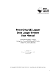
1
DNx-DIO-448 Digital Input Layer User Manual 48-channel Digital Input Layers for PowerDNA Cube and PowerDNR RACKtangle Systems June 2010 Edition Version 1.1 PN Man-DNA-DIO-448-0610 © Copyright 1998-2010 United Electronic Industries, Inc. All rights reserved. i No part of this publication may be reproduced, stored in a retrieval system, or transmitted, in any form by any means, electronic, mechanical, by photocopying, recording, or otherwise without prior written permission. Information furnished in this manual is believed to be accurate and reliable. However, no responsibility is assumed for its use, or for any infringement of patents or other rights of third parties that may result from its use. All product names listed are trademarks or trade names of their respective companies. See the UEI website for complete terms and conditions of sale: http://www.ueidaq.com/company/terms.aspx Contacting United Electronic Industries Mailing Address: 27 Renmar Avenue Walpole, MA 02081 U.S.A. For a list of our distributors and partners in the US and around the world, please see http://www.ueidaq.com/partners/ Support: Telephone: Fax: (508) 921-4600 (508) 668-2350 Also see the FAQs and online “Live Help” feature on our web site. Internet Support: Support: Web-Site: FTP Site: [email protected] www.ueidaq.com ftp://ftp.ueidaq.com Product Disclaimer: WARNING! DO NOT USE PRODUCTS SOLD BY UNITED ELECTRONIC INDUSTRIES, INC. AS CRITICAL COMPONENTS IN LIFE SUPPORT DEVICES OR SYSTEMS. Products sold by United Electronic Industries, Inc. are not authorized for use as critical components in life support devices or systems. A critical component is any component of a life support device or system whose failure to perform can be reasonably expected to cause the failure of the life support device or system, or to affect its safety or effectiveness. Any attempt to purchase any United Electronic Industries, Inc. product for that purpose is null and void and United Electronic Industries Inc. accepts no liability whatsoever in contract, tort, or otherwise whether or not resulting from our or our employees' negligence or failure to detect an improper purchase. NOTE. Specifications in this document aree subject to chnge without notice. Check with UEI for current status. ii iii iii Table of Contents Chapter 1 Introduction .................................................... 1 1.1 Organization of this manual . . . . . . . . . . . . . . . . . . . . . . . . . . . . . . . . . . . . . . . . . . . . 1 1.2 1.2.1 1.2.2 The DIO-448 Layer . . . . . . . . . . . . . . . . . . . . . . . . . . . . . . . . . . . . . . . . . . . . . . . . . . . 3 Technical Specifications . . . . . . . . . . . . . . . . . . . . . . . . . . . . . . . . . . . . . . . . . 4 Photos . . . . . . . . . . . . . . . . . . . . . . . . . . . . . . . . . . . . . . . . . . . . . . . . . . . . . . . 4 1.3 Device Architecture. . . . . . . . . . . . . . . . . . . . . . . . . . . . . . . . . . . . . . . . . . . . . . . . . . . 5 1.4 Layer Connectors and Wiring . . . . . . . . . . . . . . . . . . . . . . . . . . . . . . . . . . . . . . . . . . . 6 Chapter 2 Programming with the High Level API . . . . . . . . . . . . . . . . . . . . . . . . . . . . . . . 9 2.1 Creating a Session . . . . . . . . . . . . . . . . . . . . . . . . . . . . . . . . . . . . . . . . . . . . . . . . . . . 9 2.2 Configuring the Resource String. . . . . . . . . . . . . . . . . . . . . . . . . . . . . . . . . . . . . . . . . 9 2.3 Configuring the Timing . . . . . . . . . . . . . . . . . . . . . . . . . . . . . . . . . . . . . . . . . . . . . . . 10 2.4 Reading Data . . . . . . . . . . . . . . . . . . . . . . . . . . . . . . . . . . . . . . . . . . . . . . . . . . . . . . 10 2.5 Cleaning-up the Session. . . . . . . . . . . . . . . . . . . . . . . . . . . . . . . . . . . . . . . . . . . . . . 11 Chapter 3 Programming with the Low-Level API . . . . . . . . . . . . . . . . . . . . . . . . . . . . . . 12 Appendix . . . . . . . . . . . . . . . . . . . . . . . . . . . . . . . . . . . . . . . . . . . . . . . . . . . . . . . . . . . . . . . . 13 Index . . . . . . . . . . . . . . . . . . . . . . . . . . . . . . . . . . . . . . . . . . . . . . . . . . . . . . . . . . . . . . . . . . 14 © Copyright 2010 United Electronic Industries, Inc. Tel: 508-921-4600 Date: June 2010 www.ueidaq.com Vers: 1.1 File:DNA-DIO-448_ManualTOC.fm iv Table of Figures 1-1 1-2 1-3 1-4 1-5 1-6 1-7 1-8 DNA-DIO-448 Digital I/O Layer...................................................................................... 4 DNR-DIO-448 Digital I/O Layer...................................................................................... 5 Block Diagram of DIO-448 Device Architecture............................................................. 5 DB-62 I/O Connector Pinout .......................................................................................... 6 Physical Layout of DNA-DIO-448 Layer Board.............................................................. 7 Diagram of DNA-DIO-448 Layer Position Jumper Settings ........................................... 7 Typical Input Circuit Diagram for Channels 0 to 23 (Port 1) .......................................... 8 Typical Input Circuit Diagram for Channels 24 to 47, Port 2.......................................... 8 © Copyright 2010 United Electronic Industries, Inc. Date: June 2010 Vers: 1.1 File:DNA-DIO-448_ManualLOF.fm DNx-DIO-448 Layer Chapter 1 Introduction Chapter 1 Introduction This document outlines the feature set and use of the DNA-DIO-448 digital input layer when used with the UEI PowerDNA I/O Cube. The DNA-DIO448 is a 48-channel Digital Input Layer designed for use with the PowerDNA 3- or 6-layer Ethernet-based Cube. The DNR-DIO-448 is designed for use with a PowerDNR RACKtangle rack-mounted system. 1.1 Organization This PowerDNA DIO-448 User Manual is organized as follows: of this manual • Introduction This chapter provides an overview of DNx-DIO-448 Digital Input board features, accessories, and what you need to get started. • The DIO-448 Layer This chapter provides an overview of the device architecture, connectivity, and logic of the DIO-448 layer. • Programming with the High-Level API This chapter provides a general description of the how to create a session, configure the session for digital data acquisition/output, and format relevant data, using the Framework High-Level API. • Programming with the Low-Level API This chapter describes Low-level API commands for configuring and using the DIO-448 layer. • Appendices A. Accessories This appendix describes the accessories available for use with the DIO448 layer. © Copyright 2010 United Electronic Industries, Inc. • B. Layer Verification This appendix outlines how to verify calibration for the DIO-448 layer. • Index This is an alphabetical listing of the topics covered in this manual. Tel: 508-921-4600 Date: June 2010 www.ueidaq.com Vers: 1.1 File:DNA-DIO-448 Chap1.fm 1 DNx-DIO-448 Layer Chapter 1 Introduction Manual Conventions To help you get the most out of this manual and our products, please note that we use the following conventions: Tips are designed to highlight quick ways to get the job done, or reveal good ideas you might not discover on your own. NOTE: Notes alert you to important information. CAUTION! advises you of precautions to take to avoid injury, data loss, and damage to your boards or a system crash. Text formatted in bold typeface generally represents text you should be entered verbatim. For instance, it can represent a command, as in the following example: “You can instruct users how to run setup using a command such as setup.exe.” © Copyright 2010 United Electronic Industries, Inc. Tel: 508-921-4600 Date: June 2010 www.ueidaq.com Vers: 1.1 File:DNA-DIO-448 Chap1.fm 2 DNx-DIO-448 Layer Chapter 1 Introduction 1.2 The DIO-448 Layer The DNx-DIO-448 is a 48-channel, high performance, digital input layer designed for use in a wide variety of digital monitoring applications. To maximize throughput, the board has two 24-bit ports, each of which sends data to the PowerDNA cube in a single 24-bit write. The board can monitor all 48 bits at sustained sampling rates of more than 1 kS/second. Each of the 24-bit ports is configured with 33kOhm pullup or pulldown resistors, which makes the board ideal for monitoring contact closures as well as common voltage inputs. The resistors on each port are configured by connecting the PLEVEL pins for each group of 24 inputs on the I/O connector either to Vcc (for pullup) or ground (for pulldown). (Refer to Figure 1-4 on page 6.) A novel feature of the board is the use of an A/D converter to sense the signal level of each digital input. Using this feature, you can program the specific switching signal level for each digital input on the board, offering you the flexibility needed to function in a wide variety of applications. Hysteresis (deadband setting) is independently programmable on each 24-bit port over the full input range. For detailed information on setting hysteresis values, refer to Chapter 2 of this manual and to the DqAdv448SetLevels function in the Framework API Reference Manual. The board also offers user-programmable debouncing with delay intervals that can be set independently for each channel from 0 to 6.5 Sec. In addition, a diagnostic input mode monitors the static analog voltage on each input channel, which enables you to immediately detect and localize a short, open, marginal, or failing drive circuit. For more information, refer to Chapter 2 of this manual and to the DqAdv448SetDebouncer function in the Framework API Reference Manual. Each board provides 350 Vrms isolation between the I/O, cube, and other installed I/O layers. All inputs are protected against overvoltage to ±40VDC and also against ESD. The DIO-448 is fully supported by the UEIDAQ Framework software API, which provides a simple and complete interface to all popular programming languages, operating systems, and data acquisition/control applications, such as LabVIEW, DASYLab, and MATLAB. © Copyright 2010 United Electronic Industries, Inc. Tel: 508-921-4600 Date: June 2010 www.ueidaq.com Vers: 1.1 File:DNA-DIO-448 Chap1.fm 3 DNx-DIO-448 Layer Chapter 1 Introduction 1.2.1 Technical The technical specifications for the DNA-DIO-448 layer are listed in Table 1-1. Specifications Table 1-1. Technical Specifications Technical Specifications: Number of channels Port configuration Input high voltage Input OFF voltage Hysteresis (voltage input) Input impedance Input open circuit state Input FIFO Input Throughput Rate Diagnostic voltage measurement accuracy Input protection Input Isolation Power dissipation Operating Temp. Range Operating Humidity Vibration IEC 60068-2-6 IEC 60068-2-64 Shock IEC 60068-2-27 MTBF 1.2.2 Photos 48 digital inputs Two 24-bit ports Programmable from 0 to Vcc (default: 12 V @ Vcc = 28 VDC) Programmable from 0 to Vcc (default: <1.25 V @ 28 VDC) Programmable, 0 to Vcc (default 10.25 VDC) > 33 k Ohm. Programmable high or low via 33 kOhm pull up/pull down. Each pull up/down selection sets the configuration for 24 channels) 256 words 1 kHz max ± 25 mV (Source impedance ≤ 100 Ohm) - 25 to + 75 V, and ESD 350 Vrms 2W Tested -40 to +85 °C 95%, non-condensing 5 g, 10-500 Hz, sinusoidal 5 g (rms), 10-500 Hz, broad-band random 50 g, 3 ms half sine, 18 shocks @ 6 orientations 30 g, 11 ms half sine, 18 shocks @ 6 orientations TBD hours Figure 1-1 shows a photo of the DNA-DIO-448 board. The DNR version is basically the same except that it has a 120-pin connector that plugs into a backplane on the RACKtangle rack-mounted enclosure. See Figure 1-2. The DNR version also does not have a jumper block for setting layer position within the enclosure as the DNR version determines layer position automatically. Figure 1-1 DNA-DIO-448 Digital I/O Layer © Copyright 2010 United Electronic Industries, Inc. Tel: 508-921-4600 Date: June 2010 www.ueidaq.com Vers: 1.1 File:DNA-DIO-448 Chap1.fm 4 DNx-DIO-448 Layer Chapter 1 Introduction Figure 1-2. DNR-DIO-448 Digital I/O Layer Control Logic 32-bit 66-MHz bus DIn0 A/D Converter ... Multiplexers DIn47 Isolation The DIO-448 Layer accepts 48 digital inputs. A block diagram of the board layer is shown in Figure 1-3. Input Protection & Pull up/dn Reisistors Device Architecture Digital I/O Connector 1.3 Figure 1-3 Block Diagram of DIO-448 Device Architecture Note that the I/O part of the layer is isolated from the logic interface by inductive isolators and that overvoltage protection is provided on all inputs © Copyright 2010 United Electronic Industries, Inc. Tel: 508-921-4600 Date: June 2010 www.ueidaq.com Vers: 1.1 File:DNA-DIO-448 Chap1.fm 5 DNx-DIO-448 Layer Chapter 1 Introduction 1.4 Layer Connectors and Wiring PLEVEL 0-23 selects pullup/pulldown resistors for channels 0 to 23 The pinout of the DB-37 62-pin female connector for the DIO-448 Layer board is shown in Figure 1-4. Pin 1 2 3 4 5 6 7 8 9 10 11 12 13 14 15 16 17 18 19 20 21 Signal PLEVEL 0-23 Rsvd Rsvd Rsvd DIn 45 DIn 42 DIn 39 DIn 36 DIn 33 DIn 30 DIn 27 DIn 24 DIn 21 DIn 18 DIn 15 DIn 12 DIn 9 DIn 6 DIn 3 DIn 0 NC Pin 22 23 24 25 26 27 28 29 30 31 32 33 34 35 36 37 38 39 40 41 42 Signal PLEVEL 24-47 Gnd Gnd NC DIn 46 DIn 43 DIn 40 DIn 37 DIn 34 DIn 31 DIn 28 DIn 25 DIn 22 DIn 19 DIn 16 DIn 13 DIn 10 DIn 7 DIn 4 DIn 1 Gnd Pin 43 44 45 46 47 48 49 50 51 52 53 54 55 56 57 58 59 60 61 62 Signal Gnd NC Gnd DIn 47 DIn 44 DIn 41 DIn 38 DIn 35 DIn 32 DIn 29 DIn 26 DIn 23 DIn 20 DIn 17 DIn 14 DIn 11 DIn 8 DIn 5 DIn 2 NC PLEVEL 24-47 selects pullup/pulldown resistors for channels 24 to 47 NC - No Connection (Do not use) Rsvd - Reserved (Do not use) Figure 1-4 DB-62 I/O Connector Pinout Note that the DIO-448 inputs are numbered from DIn0 through DIn47. When power is provided to the layer, the RDY LED turns on. When no power is supplied, the RDY LED is off, and the DIO-448 layer cannot operate. © Copyright 2010 United Electronic Industries, Inc. Tel: 508-921-4600 Date: June 2010 www.ueidaq.com Vers: 1.1 File:DNA-DIO-448 Chap1.fm 6 DNx-DIO-448 Layer Chapter 1 Introduction 1 2 3 4 5 6 7 8 9 10 11 12 13 14 15 16 DNA 120-pin Bus Connector J1 Factory Use Only See Figure 1-5 for jumper locations for setting layer position. (Jumpers not used on DNR version of board) Power Connector DB-62 I/O Connector External Circuits Figure 1-5. Physical Layout of DNA-DIO-448 Layer Board 1.4.0.1 Jumper Settings A diagram of the jumper block is shown in Figure 1-6. To set the layer position jumpers, place jumpers as shown in Figure 1-6. (Not applicable to DNR version.) Jx Pins I/O 1 Layer’s Position as marked on the Faceplate* I/O 2 I/O 3 I/O 4 I/O 5 I/O 6 9-10 11-12 13-14 15-16 * All I/O Layers are sequentially enumerated from top to the bottom of the Cube - Open - Closed Figure 1-6. Diagram of DNA-DIO-448 Layer Position Jumper Settings © Copyright 2010 United Electronic Industries, Inc. Tel: 508-921-4600 Date: June 2010 www.ueidaq.com Vers: 1.1 File:DNA-DIO-448 Chap1.fm 7 DNx-DIO-448 Layer Chapter 1 Introduction 1.4.0.2 Input Circuits Each input circuit is configured as shown in Figure 1-7 or Figure 1-8. Each 24-bit port must be PLEVEL (0 - 23) 33K DIN 0 Board must be configured as as pullup or pulldown pull up, configured or pull down by by connecting PLEVEL to user connecting PLEVEL to user VCC or Vcc ground, or respectively. ground, respectively. Do NOT leave unconnected. ... ... DINx ... ... A/D Converter MUX DIN 23 47 Figure 1-7. Typical Input Circuit Diagram for Channels 0 to 23 (Port 1) Each 24-bit port must be PLEVEL (24 - 47) 33K DIN 24 0 ... DINx ... Board must be configured as as pullup or pulldown pull up, configured or pull down by by connecting PLEVEL to user connecting PLEVEL to user or respectively. ground, respectively. VCC or Vcc ground, Do NOT leave unconnected. ... ... MUX A/D Converter DIN 47 Figure 1-8. Typical Input Circuit Diagram for Channels 24 to 47, Port 2 © Copyright 2010 United Electronic Industries, Inc. Tel: 508-921-4600 Date: June 2010 www.ueidaq.com Vers: 1.1 File:DNA-DIO-448 Chap1.fm 8 DNx-DIO-448 Layer Chapter 2 Programming with the High Level API Chapter 2 Programming with the High Level API This section describes how to control the DIO-448 with the UEIDAQ high-level API, called Framework. Framework is object oriented; its objects can be manipulated in the same manner from a wide range of development environments such as Visual C++, Visual Basic or LabVIEW. The following section focuses on the C++ API, but the concept is the same no matter what programming language you use. Please refer to the “UeiDaq Framework User Manual” for more information on using other programming languages. 2.1 Creating a Session The Session object controls all operations on your PowerDNA device. Therefore, the first task is to create a session object: CUeiSession session; 2.2 Configuring Framework uses resource strings to select which device, subsystem and the Resource channels to use within a session. The resource string syntax is similar to a web URL: String <device class>://<IP address>/<Device Id>/<Subsystem><Channel list> For PowerDNA, the device class is pdna. For example, the following resource string selects digital input ports 0,1 on device 1 at IP address 192.168.100.2: "pdna://192.168.100.2/Dev1/Di0,1" NOTE: In Framework, a digital channel corresponds to a physical port on the device. You cannot configure a session only to access a subset of lines within a digital port. NOTE: Sessions are unidirectional. If your device has both input and output ports or has bidirectional ports, you need to configure two sessions: one for input and one for output. Use the method CreateDIIndustrialChannel() to program the advanced features of the DIO-448, such as the levels at which the input line states change, as well as a digital filter to eliminate glitches and spikes The following call configures the digital input ports of a DIO-448 set as device 1: session.CreateDIIndustrialChannel("pdna://192.168.100.2/Dev1/Di0:1", 1.5, 5.0, 1.0); It configures the following parameters: © Copyright 2010 United Electronic Industries, Inc. • Low Threshold: the low hysteresis threshold. • High Threshold: the high hysteresis threshold. • Digital input filter (debouncer): the minimum pulse width in ms. Use 0.0 to disable the digital input filter. Tel: 508-921-4600 Date: June 2010 www.ueidaq.com Vers: 1.1 File: DNA-DIO-448 Chap2.fm 9 DNx-DIO-448 Layer Chapter 2 Programming with the High Level API To read the voltage and current flowing through each of the digital input lines, you must treat the DIO-448 like an analog input device and create a new analog input session (different from the one you are using to read the digital states of the input lines) and configure the input lines you want to read from: CUeiSession aiSession // Read voltage from all 48 lines. Only the first parameter // “resource” is used with the DIO-448, the other parameters // are ignored. aiSession.CreateAIChannel(“pdna://192.168.100.2/Dev1/Ai0:47”, -10, 10,UeiAIChannelInputModeDifferential); 2.3 Configuring the Timing You can configure the DIO-448 to run in simple mode (point by point), buffered mode (ACB mode), or DMAP mode. • In simple mode, the delay between samples is determined by software on the host computer. • In DMAP mode, the delay between samples is determined by the DIO-448 on-board clock, and data is transferred one scan at a time between PowerDNA and the host PC. • In buffered mode, the delay between samples is determined by the DIO-448 on-board clock, and data is transferred in blocks between PowerDNA and the host PC. The following sample shows how to configure the simple mode. Please refer to the “UeiDaq Framework User Manual” to learn how to use the other timing modes. session.ConfigureTimingForSimpleIO(); aiSession.ConfigureTimingForSimpleIO(); 2.4 Reading Data Reading analog and digital data from the DIO-448 is done using reader objects. The following sample code shows how to create a scaled reader object and read samples. // Create a reader and link it to the digital session’s stream CUeiDigitalReader diReader(session.GetDataStream()); // Create a reader and link it to the digital session’s stream CUeiAnalogScaledReader aiReader(aiSession.GetDataStream()); // read one digital scan, the buffer must be big enough to contain // one value per port uInt32 data[2]; reader.ReadSingleScan(data); // Read voltages from all input lines double volts[48]; aiReader.ReadSingleScan(volts); © Copyright 2010 United Electronic Industries, Inc. Tel: 508-921-4600 Date: June 2010 www.ueidaq.com Vers: 1.1 File: DNA-DIO-448 Chap2.fm 10 DNx-DIO-448 Layer Chapter 2 Programming with the High Level API 2.5 Cleaning-up the Session The session object will clean itself up when it goes out of scope or when it is destroyed. However, you can manually clean up the session (to reuse the object with a different set of channels or parameters). session.CleanUp(); aiSession.CleanUp(); © Copyright 2010 United Electronic Industries, Inc. Tel: 508-921-4600 Date: June 2010 www.ueidaq.com Vers: 1.1 File: DNA-DIO-448 Chap2.fm 11 DNx-DIO-448 Layer Chapter 3 Programming with the Low-Level API Chapter 3 Programming with the Low-Level API The low-level API offers direct access to PowerDNA DAQBios protocol and allows you to directly access device registers. We recommend that you use the UeiDaq Framework (see Chapter 2), which is easier to use. You should need to use the low-level API only if you are using an operating system other than Windows. Please refer to the API Reference Manual document under: Start » Programs » UEI » PowerDNA » Documentation for pre-defined types, error codes, and functions for use with this layer. © Copyright 2010 United Electronic Industries, Inc. Tel: 508-921-4600 Date: June 2010 www.ueidaq.com Vers: 1.1 File:DNA-DIO-448 Chap3.fm 12 13 Appendix A. Accessories The following cables and STP boards are available for the DIO-448 layer. DNA-CBL-62 A 3ft, 62-way flat ribbon cable that connects the layer to a terminal panel. DNA-STP-62 62-way screw terminal panel. © Copyright 2010 United Electronic Industries, Inc. Tel: 508-921-4600 Date: June 2010 www.ueidaq.com Vers: 1.1 File:DNA-DIO-448 Appx.fm Index 14 Index A M A/D converter 3 Architecture 5 B Block Diagram C Manual Conventions 2 Manual Organization 1 P 5 Photo of DIO-448 4 Photos 4 Physical layout 7 Pinout 6 Programming Languages 3 Programming with high-level API Cable(s) 13 Connectors 6 D Debouncing 3 Description 3 H Hysteresis I S J Jumper Settings L Screw-Terminal Panels 13 Specifications 4 Support ii Support email [email protected] ii Support FTP Site ftp 3 Input Circuit Diagram Input Circuits 7 Isolation 3 8 //ftp.ueidaq.com ii 7 Layer Position Jumper Settings 7 © Copyright 2010 United Electronic Industries, Inc. 9 Tel: 508-921-4600 Date: June 2010 Support Web Site www.ueidaq.com www.ueidaq.com ii Vers: 1.1 File:DNA-DIO-448_ManualIX.fm