1
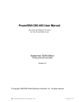
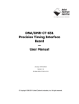
DNA/DNR-DIO-462 Guardian™
12-channel Electromechanical
Relay Output Layer
—
User Manual
12 Form C (NO/NC) SPDT Relays
Max. Operating Voltage — 220 VDC, 250 VAC
Max. Switching Capacity — 94 VA, 90 W
Rated Load —2A@30 VDC, 0.75 A@ 150 VAC continuous
Release 4.6
March 2014 Edition
PN Man-DNx-DIO-462-0314
© Copyright 1998-2013 United Electronic Industries, Inc. All rights reserved.
i
No part of this publication may be reproduced, stored in a retrieval system, or transmitted, in any form
by any means, electronic, mechanical, by photocopying, recording, or otherwise without prior written
permission.
Information furnished in this manual is believed to be accurate and reliable. However, no responsibility
is assumed for its use, or for any infringement of patents or other rights of third parties that may result
from its use.
All product names listed are trademarks or trade names of their respective companies.
See the UEI website for complete terms and conditions of sale:
http://www.ueidaq.com/company/terms.aspx
Contacting United Electronic Industries
Mailing Address:
27 Renmar Avenue
Walpole, MA 02081
U.S.A.
For a list of our distributors and partners in the US and around the world, please see
http://www.ueidaq.com/partners/
Support:
Telephone:
Fax:
(508) 921-4600
(508) 668-2350
Also see the FAQs and online “Live Help” feature on our web site.
Internet Support:
Support:
Web-Site:
FTP Site:
[email protected]
www.ueidaq.com
ftp://ftp.ueidaq.com
Product Disclaimer:
WARNING!
DO NOT USE PRODUCTS SOLD BY UNITED ELECTRONIC INDUSTRIES, INC. AS CRITICAL
COMPONENTS IN LIFE SUPPORT DEVICES OR SYSTEMS.
Products sold by United Electronic Industries, Inc. are not authorized for use as critical components in
life support devices or systems. A critical component is any component of a life support device or
system whose failure to perform can be reasonably expected to cause the failure of the life support
device or system, or to affect its safety or effectiveness. Any attempt to purchase any United Electronic
Industries, Inc. product for that purpose is null and void and United Electronic Industries Inc. accepts
no liability whatsoever in contract, tort, or otherwise whether or not resulting from our or our
employees' negligence or failure to detect an improper purchase.
NOTE— Specifications in this document are subject to change without notice. Check with UEI
for current status.
ii
Table of Contents
Chapter 1 Introduction
.................................................... 1
1.1
Organization of this Manual . . . . . . . . . . . . . . . . . . . . . . . . . . . . . . . . . . . . . . . . . . . . 1
1.2
The DIO-462 Layer . . . . . . . . . . . . . . . . . . . . . . . . . . . . . . . . . . . . . . . . . . . . . . . . . . . 3
1.3
Features . . . . . . . . . . . . . . . . . . . . . . . . . . . . . . . . . . . . . . . . . . . . . . . . . . . . . . . . . . . 5
1.4
1.4.1
1.4.2
Device Architecture. . . . . . . . . . . . . . . . . . . . . . . . . . . . . . . . . . . . . . . . . . . . . . . . . . . 6
Guardian Feature. . . . . . . . . . . . . . . . . . . . . . . . . . . . . . . . . . . . . . . . . . . . . . . 6
Circuit Breaker Function . . . . . . . . . . . . . . . . . . . . . . . . . . . . . . . . . . . . . . . . . 6
1.5
1.5.1
Layer Connectors and Wiring . . . . . . . . . . . . . . . . . . . . . . . . . . . . . . . . . . . . . . . . . . . 7
Jumper Settings . . . . . . . . . . . . . . . . . . . . . . . . . . . . . . . . . . . . . . . . . . . . . . . . 8
1.6
Anti-Kickback Diodes . . . . . . . . . . . . . . . . . . . . . . . . . . . . . . . . . . . . . . . . . . . . . . . . . 9
Chapter 2 Programming with the High Level API . . . . . . . . . . . . . . . . . . . . . . . . . . . . . . 10
2.1
2.1.1
2.1.2
2.1.3
Creating a Session . . . . . . . . . . . . . . . . . . . . . . . . . . . . . . . . . . . . . . . . . . . . . . . . . .
Configuring the Resource String . . . . . . . . . . . . . . . . . . . . . . . . . . . . . . . . . .
Configuring the Timing . . . . . . . . . . . . . . . . . . . . . . . . . . . . . . . . . . . . . . . . . .
Writing Data to the Output Port . . . . . . . . . . . . . . . . . . . . . . . . . . . . . . . . . . .
10
10
11
11
2.2
Monitoring the Current . . . . . . . . . . . . . . . . . . . . . . . . . . . . . . . . . . . . . . . . . . . . . . . 11
2.3
Cleaning-up the Session. . . . . . . . . . . . . . . . . . . . . . . . . . . . . . . . . . . . . . . . . . . . . . 12
Chapter 3 Programming with the Low-level API . . . . . . . . . . . . . . . . . . . . . . . . . . . . . . . 13
Appendix A - Accessories. . . . . . . . . . . . . . . . . . . . . . . . . . . . . . . . . . . . . . . . . . . . . . . . . . . 14
Index
. . . . . . . . . . . . . . . . . . . . . . . . . . . . . . . . . . . . . . . . . . . . . . . . . . . . . . . . . . . . . . . . . . 15
© Copyright 2010
United Electronic Industries, Inc.
Tel::508-921-4600
Date: March 2014
www.ueidaq.com
Vers: 1.0
DNA-DIO-462-ManualTOC.fm
List of Figures
Chapter 1 Introduction . . . . . . . . . . . . . . . . . . . . . . . . . . . . . . . . . . . . . . . . . . . . . . . . . . . . 1
1-1
A DNR-DIO-462 Digital I/O Layer .................................................................................. 4
1-2
DNx-DIO-462 Device Architecture ................................................................................. 6
1-3
DB-37 I/O Connector Pinout .......................................................................................... 7
1-4
Physical Layout of DNA-DIO-462 Layer Board.............................................................. 8
1-5
Diagram of DNA-DIO-462 Layer Position Jumper Settings ........................................... 8
© Copyright 2010
United Electronic Industries, Inc.
Tel::508-921-4600
Date: March 2014
www.ueidaq.com
Vers: 1.3
DNA-DIO-462-ManualLOF.fm
DNx-DIO-462 Relay Output Board
Chapter 1
Introduction
Chapter 1
Introduction
This document outlines the feature set and use of the DNA/DNR-DIO-462
electromechanical relay output layer when used with the PowerDNA I/O Cube or
RACKtangle chassis, respectively.
1.1
Organization This PowerDNA DNx-DIO-462 User Manual is organized as follows:
of this Manual
• Introduction
This chapter provides an overview of PowerDNA DNx-DIO-462
Electromechanical Relay Drive Output board features, accessories, and
software.
©
Copyright
2010 all rights
reserved
United
Electronic
Industries,
United Electronic Industries, Inc.
Tel: 781-821-2890
Inc.
•
The DIO-462 Layer
This chapter provides an overview of the device architecture, connectivity, and logic of the DNx-DIO-462 layer.
•
Programming with the High-Level API
This chapter provides a general description of the how to create a session, configure the session for relay drive/output, and format relevant
data.
•
Programming with the Low-Level API
This chapter describes Low-level API commands for configuring and
using the DNx-DIO-462 layer.
•
Appendix – Accessories
This appendix describes the accessories available for use with the
DNx-DIO-462 layer.
•
Index
This is an alphabetical listing of the topics covered in this manual.
Tel: 508-921-4600
www.ueidaq.com
Date: March Printed
2014 03. 05. 2014
www.ueidaq.com
Vers:0.5
4.6
File: DNA-DIO-462
Fax: 781-821-2891
Chap1.fm
1
DNx-DIO-462 Relay Output Board
Chapter 1
Introduction
Manual Conventions
To help you get the most out of this manual and our products, please note that
we use the following conventions:
Tips are designed to highlight quick ways to get the job done, or
reveal good ideas you might not discover on your own.
NOTE: Notes alert you to important information.
CAUTION! advises you of precautions to take to avoid injury, data loss,
and damage to your boards or a system crash.
Text formatted in bold typeface generally represents text you should be entered
verbatim. For instance, it can represent a command, as in the following example: “You can instruct users how to run setup using a command such as
setup.exe.”
Before plugging any I/O connector into the Cube or Layer, be sure
to remove power from all field wiring. Failure to do so may cause
severe damage to the equipment.
©
Copyright
2010 all rights
reserved
United
Electronic
Industries,
United Electronic Industries, Inc.
Tel: 781-821-2890
Inc.
Tel: 508-921-4600
www.ueidaq.com
Date: March Printed
2014 03. 05. 2014
www.ueidaq.com
Vers:0.5
4.6
File: DNA-DIO-462
Fax: 781-821-2891
Chap1.fm
2
DNx-DIO-462 Relay Output Board
Chapter 1
Introduction
1.2
The DIO-462
Layer
The DNx-DIO-462 is a 12-channel Electromechanical Relay Output Layer
designed for driving solenoids, motors, or other inductive loads attached to a
PowerDNA Cube or RACKtangle. The board is available in two versions, the
DNA-DIO-462 for mounting in UEI Cube products, and DNR-DIO-462, for insertion into UEI RACKtangle and HalfRACK chassis.
The DNx-DIO-462 has 12 digital outputs that can be configured to provide output
control for 12 channels (total). The maximum current drive is 2 A @ 30 VDC per
channel (or 0.75A @ 125 VAC).
NOTE: Users who connect inductive loads to the DIO-462 must provide antikickback diodes on each such output.
The technical specifications for the DIO-462 layer are listed in Table 1-1 below.
Table 1-1. DNx-DIO-462 Technical Specifications
Technical Specifications:
Output specifications
Rated Load
Max Switching Capacity
Max Operating Voltage
Min Permissible Load
Contact Material
Contact ON impedance
Contact OFF impedance
Off Leakage Current
Turn-On Time
Turn-Foff Time
Max Operating Freq.
Service Life
Mechanical
Electrical
Monitor/circuit breaker specs
Resolution
Range
©
Copyright
2010 all rights
reserved
United
Electronic
Industries,
United Electronic Industries, Inc.
Tel: 781-821-2890
Inc.
2 A at 30 VDC, 0.75 A at 125 VAC continuous
94 VA, 90 W
220 VDC, 250 VAC
10 μA, 10 mVDC
Ag (Au clad)
200 mOhm max (at the I/O connector)
>100 MOhm
< 100 μA
4 mS max, 2.5 mS typ
4 mS max, 1.5 mS typ
125 operations/second (36000/hour limit)
100 000 000 min
100 000 at 2 A 30 VDC or 0.75 A and 125 VAC
16 bit
+150/-30 VDC
±2 A DC
0.3-2 A AC
-55/+100 °C
Accuracy
DC Voltage
DC Current
AC Voltage
Relay Temperature
Protection
DC Voltage
DC Current
AC Current
Relay Temperature
Disconnection Time
Power up / reboot state
Power dissipation
Isolation
Operating Temp. Range
Operating Humidity
Vibration IEC 60068-2-6
IEC 60068-2-64
Shock
IEC 60068-2-27
5% of measurement + 0.25% of the full scale
5% of measurement + 0.25% of the full scale
15% of measurement + 1% of the full scale
±2 °C typ
(only one type activated per channel)
±5 V to ±220 V
50 mA to 2 A
400 mA to 2 A
0-85 °C
1 sec
Off (NC Energized)
< 3.5 W
350 Vrms
Tested -40 to +85 °C
95%, non-condensing
5 g, 10-500 Hz, sinusoidal
5 g (rms), 10-500 Hz, broad-band random
MTBF
260,000 hours
50 g, 3 ms half sine, 18 shocks @ 6 orientations
30 g, 11 ms half sine, 18 shocks @ 6 orientations
Tel: 508-921-4600
www.ueidaq.com
Date: March Printed
2014 03. 05. 2014
www.ueidaq.com
Vers:0.5
4.6
File: DNA-DIO-462
Fax: 781-821-2891
Chap1.fm
3
DNx-DIO-462 Relay Output Board
Chapter 1
Introduction
Figure 1-1 is a photo of the DNR-DIO-462 version of the DNx-DIO-462 board.
The DNA version is functionally identical except that it is designed for insertion
into a UEI Cube-type chassis
120-pin DNR
bus connector
IRQ Jumpers (Do not change)
DB-37 (female)
37-pin I/O connector
Figure 1-1. A DNR-DIO-462 Digital I/O Layer
©
Copyright
2010 all rights
reserved
United
Electronic
Industries,
United Electronic Industries, Inc.
Tel: 781-821-2890
Inc.
Tel: 508-921-4600
www.ueidaq.com
Date: March Printed
2014 03. 05. 2014
www.ueidaq.com
Vers:0.5
4.6
File: DNA-DIO-462
Fax: 781-821-2891
Chap1.fm
4
DNx-DIO-462 Relay Output Board
Chapter 1
Introduction
1.3
Features
The main features of the PowerDNx DNA-DIO-462 Relay Drive Output Layer
are:
•
•
•
•
•
•
•
•
•
•
•
•
•
•
©
Copyright
2010 all rights
reserved
United
Electronic
Industries,
United Electronic Industries, Inc.
Tel: 781-821-2890
Inc.
12 Form C electromechanical relay outputs (total)
2A @ 30VDC or 0.75A @125 VAC continuous per channel maximum
current rating
220 VDC or 250 VAC maximum operating voltage
Ideal for driving solenoids, motors, or other inductive loads (user must
provide anti-kickback diodes)
10 uA, 10 mV DC min permissible Load
Programmable Overcurrent Duration Limits
Monitors each channel’s output voltage and current, allowing
automatic detection of shorts/opens and other system failures
DNR-DIO-462 for use with RACKtangle I/O chassis
DNA-DIO-462 for use with “Cube” I/O chassis
200 milliOhm ON resistance (not including cable)
Output Throughput rate 125 updates per second max
Interrupt on over- and under-current conditions
Contact Material Ag (Au clad)
OFF leakage current <100 uA
Tel: 508-921-4600
www.ueidaq.com
Date: March Printed
2014 03. 05. 2014
www.ueidaq.com
Vers:0.5
4.6
File: DNA-DIO-462
Fax: 781-821-2891
Chap1.fm
5
DNx-DIO-462 Relay Output Board
Chapter 1
Introduction
1.4
Device
Architecture
The DNx-DIO-462 Layer has 12 Form C relay outputs. A block diagram of the
board is shown in Figure 1-2.
Block Diagram:
Converter
Digital
Isolator
Relays
32-bit 66-MHz bus
A/D
Divider
Relay
Drivers
Voltage
Control Logic
DC/DC
Sense
Resistors
I/O Connector
Each relay provides the
functionality shown
Optical Isolation
Figure 1-2. DNx-DIO-462 Device Architecture
Note that the I/O part of the layer is isolated from the logic interface and that
overload protection is provided on all output lines.
1.4.1
Guardian
Feature
As shown in Figure 1-2, the Guardian feature of the DIO-462 monitors the voltage drop across a series resistor in the circuit of each output relay, continuously
sensing AC current, DC current, and output voltage relative to the COM terminal. An on-board ADC detects undercurrent, overcurrent, shorts, opens, and
other off-normal conditions (such as high/low temperature), all of which are userprogrammable as to magnitude and/or duration.
The Guardian feature is a valuable diagnostic and troubleshoooting tool for
ensuring system uptime.
1.4.2
Circuit
Breaker
Function
The DIO-462 can be programmed to provide a circuit breaker function when any
of the measurements exceeds a user-defined limit.
After a fault is detected, this circuit breaker function can be set to re-connect in
either of 2 ways:
•
Auto reconnect: In this mode, the board will reconnect after a 1 second
delay and test the limit again. This will result in the relay continually
cycling on and off until the overlimit condition is resolved.
•
User re-enable: In this mode, the relay will be set to the OFF state and
remain there until the user software re-writes the ON command to the
relay.
A ‘1’ written to the digital output for any given relay will switch the relay ON,
which connects COM to the N.O. contact.The circuit breaker function always
acts to return the relay to the ‘0’ or OFF state, which will connect the COM back
to the N.C. contact. Thus, the circuit breaker can only disconnect a current that
is flowing through the COM-N.O. connection. The user program can always read
the current flowing through the relay regardless of which state the contacts are
in.
When measuring voltage, the situation is reversed from the current measurement. In such cases, the voltage will be zero for the contact that is connected to
the COM terminal and will be readable for the disconnected terminal.
©
Copyright
2010 all rights
reserved
United
Electronic
Industries,
United Electronic Industries, Inc.
Tel: 781-821-2890
Inc.
Tel: 508-921-4600
www.ueidaq.com
Date: March Printed
2014 03. 05. 2014
www.ueidaq.com
Vers:0.5
4.6
File: DNA-DIO-462
Fax: 781-821-2891
Chap1.fm
6
DNx-DIO-462 Relay Output Board
Chapter 1
Introduction
The limit set function used by the breaker circuit always assumes that a voltage
or current farther from zero is greater than one that is closer to zero. For example, a current limit of +200mA will disconnect when a current of +201mA is
detected and a current limit of negative 200mA will disconnect with a current of
-201mA.
1.5
Layer
Connectors
and Wiring
The pinout of the DB-37 37-pin female connector for the DNx-DIO-462 Layer
board is shown in Figure 1-3.
NC-0 - 1
COM-0 - 2
NO-1 - 3
NC-2 - 4
COM-2 - 5
NO-3 - 6
NC-4 - 7
COM-4 - 8
NO-5 - 9
NC-6 - 10
COM-6 - 11
NO-7 - 12
NC-8 - 13
COM-8 - 14
NO-9 - 15
NC-10 - 16
COM-10 - 17
NO-11 - 18
rsvd - 19
20
21
22
23
24
25
26
27
28
29
30
31
32
33
34
35
36
37
- NO-0
- NC-1
- COM-1
- NO-2
- NC-3
- COM-3
- NO-4
- NC-5
- COM-5
- NO-6
- NC-7
- COM-7
- NO-8
- NC-9
- COM-9
- NO-10
- NC-11
- COM-11
Figure 1-3. DB-37 I/O Connector Pinout
For software compatibility with other UEI DIO products, the 12 output groups of
the DIO-462 are numbered from NO-0, NC-0, COM-0 through NO-11, NC-11,
COM-11. Note that the output of each channel is a set of three pins for NC contacts, NO contacts, and COM.
DO 0 uses AI channels 0 to 4 to measure NO voltage, DC current, AC current,
NC voltage and ADC temperature; and in a similar way for remaining channels:
DO 0
DO 1
DO 2
DO 3
DO 4
DO 5
DO 6
DO 7
DO 8
DO 9
DO 10
DO 11
©
Copyright
2010 all rights
reserved
United
Electronic
Industries,
United Electronic Industries, Inc.
Tel: 781-821-2890
Inc.
NO DC AC NC °t
0
1
2
3
4
8
9
10
11 12
16
17
18
19 20
24
25
26
27 28
32
33
34
35 36
40
41
42
43 44
48
49
50
51 52
56
57
58
59 60
64
65
66
67 68
72
73
74
75 76
80
81
82
83 84
88
89
90
91 92
Tel: 508-921-4600
www.ueidaq.com
Date: March Printed
2014 03. 05. 2014
www.ueidaq.com
Vers:0.5
4.6
File: DNA-DIO-462
Fax: 781-821-2891
Chap1.fm
7
DNx-DIO-462 Relay Output Board
Chapter 1
Introduction
When power is provided to the layer, the RDY LED on the PowerDNA Cube
turns on. When no power is supplied, the RDY LED is off, and the DNx-DIO-462
layer cannot operate.
Before plugging any I/O connector into the Cube or Layer, be sure
to remove power from all field wiring. Failure to do so may cause
severe damage to the equipment.
1.6
Anti-Kickback
Diodes
CAUTION! Use of the DIO-462 to drive inductive loads requires installation of
anti-kickback diodes on each such output. Installation of these diodes is the
responsibility of the user. Failure to provide these diodes can cause damage to
components of the board.
©
Copyright
2010 all rights
reserved
United
Electronic
Industries,
United Electronic Industries, Inc.
Tel: 781-821-2890
Inc.
Tel: 508-921-4600
www.ueidaq.com
Date: March Printed
2014 03. 05. 2014
www.ueidaq.com
Vers:0.5
4.6
File: DNA-DIO-462
Fax: 781-821-2891
Chap1.fm
8
DNx-DIO-462 Relay Output Board
Chapter 2
Programming with the High Level API
Chapter 2
Programming with the High Level API
This section describes how to control the DNA-DIO-462 using the UeiDaq
Framework High Level API.
UeiDaq Framework is object oriented and its objects can be manipulated in the
same manner from different development environments such as Visual C++,
Visual Basic or LabVIEW.
The following section focuses on the C++ API, but the concept is the same no
matter what programming language you use.
Please refer to the “UeiDaq Framework User Manual” for more information on
use of other programming languages.
2.1
Creating a
Session
The Session object controls all operations on your PowerDNA device. Therefore, the first task is to create a session object:
CUeiSession session;
2.1.1
Configuring
the Resource
String
UeiDaq Framework uses resource strings to select which device, subsystem
and channels to use within a session. The resource string syntax is similar to a
web URL:
<device class>://<IP address>/<Device Id>/<Subsystem><Channel list>
For PowerDNA, the device class is pdna.
For example, the following resource string selects digital output channels 0,1,2,3
on device 1 at IP address 192.168.100.2: "pdna://192.168.100.2/Dev1/Do0:3"
NOTE: In Framework, a digital channel corresponds to a physical port on the
device. You cannot configure a session only to access a subset of lines
within a digital port.
NOTE: Sessions are unidirectional. If your device has both input and output
ports or has bidirectional ports, you need to configure two sessions: one
for input and one for output.
The DIO-462 is known as an intelligent digital output device. It can monitor the
current flowing through each of its digital lines and open or close a line when the
current goes above or below specified current limits.
You can configure the device to attempt to close the connection after a programmed delay whenever an over- or under-current condition occurs.
The following call configures the digital output port of a DIO-462 set as device 1:
// Configure session to write to port 0 on device 1
session.CreateDOProtectedChannel("pdna://192.168.100.2/Dev1/Do0",
-0.01,
0.01,
200.0,
false,
50.0);
©
Copyright
2010 all rights
reserved
United
Electronic
Industries,
United Electronic Industries, Inc.
Tel: 781-821-2890
Inc.
Tel: 508-921-4600
www.ueidaq.com
Date: March Printed
2014 03. 05. 2014
www.ueidaq.com
Vers:0.5
4.6
File: DNA-DIO-462
Fax: 781-821-2891
Chap2.fm
10
DNx-DIO-462 Relay Output Board
Chapter 2
Programming with the High Level API
It configures the following parameters:
2.1.2
Configuring
the Timing
•
Under-current limit: when the current goes below this limit, the line
opens.
•
Over-current limit: when the current goes above this limit, the line
opens.
•
Current sampling rate: the rate at which the DIO-462 monitors current.
This rate has a direct influence on how fast the DIO-462 reacts to an
under or over-current condition.
•
The retry status: specifies whether the DIO-462 attempts to close the
circuit after an over or under current condition.
•
The retry rate: specifies how often the DIO-462 attempts to close the
circuit.
You can configure the DNA-DIO-462 to run in simple mode (point by point) only.
Use of ACB mode is not currently supported.
In simple mode, the delay between samples is determined by software on the
host computer.
The following sample shows how to configure the simple mode. Please refer to
the “UeiDaq Framework User’s Manual” to learn how to use the other timing
modes.
session.ConfigureTimingForSimpleIO();
2.1.3
Writing Data to Writing data is done using a writer object. The following sample shows how to
create a writer object and write data.
the Output
Port
// Create a writer and link it to the session’s stream
CUeiDigitalWriter writer(session.GetDataStream());
// write one scan, the buffer must contain
// one value per channel
uInt32 data = 0xFEFE;
writer.WriteSingleScan(&data);
2.2
Monitoring
the Current
You can monitor the current measured at each digital line.
Use an analog Input session the same way you would measure voltage from an
analog Input device.
The following code shows how to measure current out of the first 4 digital lines:
CUeiSession aiSs;
aiSs.CreateAIChannel("pdna://192.168.100.2/Dev1/Ai0:3"
-10.0, 10.0,
UeiAIChannelInputModeDifferential);
aiSs.ConfigureTimingForSimpleIO();
CUeiAnalogScaledReader aiReader(aiSs.GetDataStream());
double currents[8];
aiReader.ReadSingleScan(currents);
©
Copyright
2010 all rights
reserved
United
Electronic
Industries,
United Electronic Industries, Inc.
Tel: 781-821-2890
Inc.
Tel: 508-921-4600
www.ueidaq.com
Date: March Printed
2014 03. 05. 2014
www.ueidaq.com
Vers:0.5
4.6
File: DNA-DIO-462
Fax: 781-821-2891
Chap2.fm
11
DNx-DIO-462 Relay Output Board
Chapter 2
Programming with the High Level API
2.3
Cleaning-up
the Session
The session object will clean itself up when it goes out of scope or when it is
destroyed. To reuse the object with a different set of channels or parameters,
you can manually clean up the session as follows:
session.CleanUp();
©
Copyright
2010 all rights
reserved
United
Electronic
Industries,
United Electronic Industries, Inc.
Tel: 781-821-2890
Inc.
Tel: 508-921-4600
www.ueidaq.com
Date: March Printed
2014 03. 05. 2014
www.ueidaq.com
Vers:0.5
4.6
File: DNA-DIO-462
Fax: 781-821-2891
Chap2.fm
12
DNx-DIO-462 Relay Output Board
Chapter 3
Programming with the Low-level API
Chapter 3
Programming with the Low-level API
The low-level API offers direct access to PowerDNA DAQBios protocol and
allows you to directly access device registers.
Where possible, we recommend that you use the UeiDaq Framework (see
Chapter 2), which is easier to use.
You should need to use the low-level API only if you are using an operating
system other than Windows.
Please refer to the API Reference Manual document under:
Start » Programs » UEI » PowerDNA » Documentation
for pre-defined types, error codes, and functions for use with this layer.
©
Copyright
2010 all rights
reserved
United
Electronic
Industries,
United Electronic Industries, Inc.
Tel: 781-821-2890
Inc.
Tel: 508-921-4600
www.ueidaq.com
Date: March Printed
2014 03. 05. 2014
www.ueidaq.com
Vers:0.5
4.6
File: DNA-DIO-462
Fax: 781-821-2891
Chap3.fm
13
DNx-DIO-462 Layer
Appendix
A. Accessories
The following cables and STP boards are available for the DIO-462 layer.
DNA-CBL-37
A 3ft, 37-way flat ribbon cable that connects the layer to a terminal panel.
DNA-STP-37
37-way screw terminal panel.
©
Copyright
2010 all rights
reserved
United
Electronic
Industries,
United Electronic Industries, Inc.
Tel: 781-821-2890
Inc.
Tel: 508-921-4600
www.ueidaq.com
Date: March Printed
2014 03. 05. 2014
www.ueidaq.com
Vers:0.5
4.6
File: DNA-DIO-462
Fax: 781-821-2891
Appx.fm
14
15
Index
A
Low-level API
Architecture
6
B
M
Monitoring the Current
Block Diagram
6
O
C
Organization
Cable(s) 14
Caution 7
Cleaning-up the Session 12
Configuring the Resource String
Configuring the Timing 11
Conventions 2
Creating a Session 10
D
Description
F
Features
13
10
5
High Level API
Jumper Settings
Photo of DIO-462 4
Physical Layout 8
Pinout 7
S
Screw Terminal Panels 14
Specifications 3
Support ii
Support email
[email protected] ii
Support FTP Site
ftp
//ftp.ueidaq.com ii
10
J
1
P
3
H
11
Support Web Site
www.ueidaq.com
8
ii
W
Writing Data to the Output Port 11
L
Layer Position Jumper Settings 8
© Copyright 2010
United Electronic Industries, Inc.
Tel: 508-921-4600
Date: March 2014
www.ueidaq.com
Vers: 4.6
File: DNA-DIO-462-ManualIX.fm