1
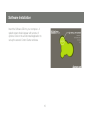
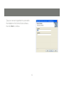
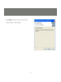
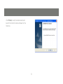
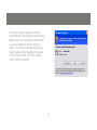
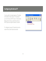
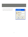
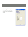
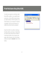
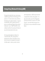
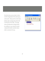
Installation Guide
USB 2.0 Hi-Speed 2-Port Multifunction Print and Storage Server
User Manual
GMFPSU22W6
PART NO. M0389
Introduction
Thank you for purchasing the IOGEAR GMFPSU22W6 2 Port USB 2.0 Multifunction Print and Storage
Server (hereafter referred to as “server”). This server is designed to connect your All-In-One/Multifunction
devices, standard printers, and USB storage devices (hard drives, flash drives, and memory card readers)
to your network, allowing all network users access to these shared USB resources.
About this Manual
This manual provides introductory information as well as detailed instructions on how to set up and manage the IOGEAR GMFPSU22W6 in various network environments.
To fully benefit from this document, you should be familiar with basic networking principles. The instructions described in this manual are based on the settings in a new server. If needed, you can reset the
server back to the factory defaults. For details, please refer to the chapter “Restore Factory Defaults”.
Table of Contents
Package Contents
6
Customer Support
29
Physical Description
7
Radio & TV Interference Statement
30
Hardware Installation
9
Limited Warranty
31
Software Installation
10
Configuring the Server IP
18
Printer/Fax/Scanner Setup (Virtual USB)
21
Storage Setup (Windows File Sharing/SMB)
23
Storage Setup (Virtual USB)
24
Restore Factory Defaults
28
Package Contents
Verify that nothing is missing from the package by using the checklist below. Please contact your dealer
if anything is missing or damaged. All packing materials are recyclable. Please confirm the items in the
package below:
1 x USB Multifunction Print and Storage Server
1 x Quick Start Guide
1 x Software CD
1 x Power adapter
1 x Warranty/Registration card
Physical Description
1. Power Adaptor Connector: DC IN 12V/1A adapter
2. Init Button: restores all settings to default values
3. Ethernet Connector: a twisted pair category 5 cable
4. USB Host Ports: USB 1.1/2.0 low, full, and hi-speed compliant
5. Indicator Lights
Indicator
Behavior
Description
Power
Lit
Power On
Not lit
Power off/System error
Lit
Network connected
Not Lit
No physical connection to network
Blinking
Activity on network
Not lit
No activity on network
Lit
USB device connected
Blinking
Connected USB device error
Not lit
No physical connection to USB device
Lit
USB device connected
Blinking
Connected USB device error
Not lit
No physical connection to USB device
Link
Status
USB1
USB2
Hardware Installation
Make sure that your USB devices are switched off and that the server’s power adapter is disconnected.
Connect the print and/or storage devices to the server’s USB ports.
Connect the server to the network with the included Ethernet cable.
Turn on the USB devices and make sure they are ready for use.
Connect the power adapter to the server. The power indicator will light up and USB1 and USB2 indicators
will flash in turn. When the Link indicator lights up, the Server is correctly connected to the network. When
USB1 and USB2 indicators do not flash, the Server is working normally.
Software Installation
Insert the Software CD into your computer. A
splash screen should appear with a menu of
options. Click on the words Install Application to
set up the server’s Control Center software.
10
Click Next to continue the installation wizard.
11
Type your name and organization to personalize
the installation of the Control Center software,
then click Next to continue.
12
Click Change… if you would like to install the
software to somewhere besides the default
location, then click Next to continue.
13
Click Install and wait a moment for the Control
Center software to finish loading.
14
Click Finish to exit the install wizard and
launch the Control Center software for the
first time.
15
If you have a software firewall you may be
alerted that the Control Center is being blocked.
Make sure that you unblock the Control Center
or you may experience difficulty using your
server. If you need to manually configure your
firewall, make sure the following ports are open
for both TCP and UDP: 7303, 7305, 20005,
30201, 30202, and 30203.
16
After a moment your print server should appear
in the server list. Click the server name once
and any attached devices should be listed below it. This means your Control Center software
is installed properly. You may close the window
using the X in the top right corner and the
Control Center will continue to run in the background. If you wish to open the Control Center
again simply double-click the grey IOGEAR icon
in the system tray area by your clock.
17
Configuring the Server IP
You may wish to manually assign an IP address
to the server in some cases. For example, if
you do not have a DHCP server on the network.
Most users who have a router that acts as a
DHCP server can skip this section, however.
To configure the server IP, double click on the
server in the Control Center’s server list.
18
At the prompt, enter the administrator username
(default: admin) and password (default: admin).
19
After you have logged in successfully, select
the TCP/IP tab. Here you may select Static IP
and manually configure all network settings for
the server.
20
Printer/Fax/Scanner Setup (Virtual USB)
Your print server supports a technology called
Virtual USB in addition to more traditional print
server ports. A Virtual USB connection allows
your printer software to think the printer is connected directly to your computer, for maximum
compatibility. All fax and scan features of a
multifunction printer will work as expected.
Using this method is very similar to setting up
the printer without a print server. Simply follow
your printer’s setup instructions but instead of
connecting the printer to the computer when
asked, select the printer in the Control Center
software and press the Connect button on the
toolbar.
21
Your printer should be detected and installed automatically at this point. You can repeat this setup
procedure on all your computers as needed. One
weakness of the Virtual USB technology is that only
one computer can be connected to the printer at a
time. For this reason it is recommended that you
set your printer to auto-connect if you will be using
it regularly. In the Control Center software select
the printer again and click on the Auto-Connect
Printer button on the toolbar, then on Set AutoConnect Printer. You will see a list of all printer
icons available on your computer. Check the box in
front of the appropriate model and click the Apply
button. Now whenever you print a document the
Control Center software will attempt to automatically restore the link to your printer.
22
Storage Setup (Windows File Sharing/SMB)
with multiple disks or a USB hub) and the third
x represents the number of the partition. You
may read or write to any FAT or FAT32 disk in
this way, and read but not write to NTFS disks
this way. If you need read/write access to an
NTFS disk you must use Virtual USB mode (see
below).
Storage devices attached to your server are accessible through Windows File Sharing and FTP
protocols. For local network access, Windows
File Sharing is the preferred method. To browse
the shared files, start by opening Internet Explorer or any Windows Explorer window with an
Address bar. Type “\\GMFPSU22W6” into the
address bar (without the quotes) and hit enter to
see what is being shared by the server.
All storage will be labeled according to the
convention USBx_DxPx, where the first x
represents the number of the USB port of the
server, the second x represents the number of
the Disk (usually 1 unless you attach a device
23
Storage Setup (Virtual USB)
To gain full control of NTFS disks you will need to use the Virtual USB mode for storage devices. In this
mode only one computer has access to a disk at a time, but any disk operation is possible including
formatting or partitioning. Once you turn on Virtual USB mode for storage devices, all storage devices can
only be accessed in this way. Plan carefully which mode is the best match for your needs.
24
To turn on Virtual USB mode, open the Control
Center software and double click on the
server name in the list. Enter the administrator username (default: admin) and password
(default: admin) at the prompt. Switch to the
Supported Protocols tab. In the lower right,
select Virtual USB mode for storage access.
Click Apply and allow the server to restart so
that the change takes effect.
25
Once this is done, you may connect or disconnect from storage devices in the same way you
would a printer. Simply open the Control Center
interface, select a storage device and click the
Connect button in the toolbar. The storage
device will be detected as if plugged directly
into a USB port on your computer. No other
computers will be able to access the device
while it is connected in this way.
26
When you are done using the drive, click the
Safely Remove Hardware icon in the tray area
by your clock to prevent further communication
with the drive and help protect against data loss.
Once this step is completed you may use the
Control Center software to disconnect the drive
and allow others to connect to it.
27
Restore Factory Defaults
If you are having difficulty finding or connecting to your print server using the Control Center software due
to network issues or a forgotten password, you can clear all settings on the server using the Init button on
the device. To properly reset all settings to factory defaults, unplug the power adapter from the device.
Then hold the Init button and plug the power adapter back in. Instead of blinking alternately as during
a normal startup, the USB1 and USB2 lights should begin blinking at the same time. Unplug the power
adapter once again, and then plug in the adapter without holding the Init button. The server should go
through the normal startup process and all network and password settings will be at defaults.
28
Customer Support
Should you require any technical assistance, call toll-free: 866-9-IOGEAR (866-946-4327) or visit our
website at http://www.iogear.com for the latest product information and support files. This document is
subject to change without prior notice.
29
Radio & TV Interference Statement
WARNING!!! This equipment generates, uses and can radiate radio frequency energy and, if not installed
and used in accordance with the instruction manual, may cause interference to radio communications.
This equipment has been tested and found to comply with the limits for a Class B computing device
pursuant to Subpart J of Part 15 of FCC Rules, which are designed to provide reasonable protection
against such interference when operated in a commercial environment. Operation of this equipment in a
residential area is likely to cause interference, in which case the user at his own expense will be required to
take whatever measures may be required to correct the interference.
30
Limited Warranty
IN NO EVENT SHALL THE DIRECT VENDOR’S LIABILITY FOR DIRECT, INDIRECT, SPECIAL, INCIDENTAL OR CONSEQUENTIAL DAMAGES RESULTING FROM THE USE OF THE PRODUCT, DISK, OR ITS
DOCUMENTATION EXCEED THE PRICE PAID FOR THE PRODUCT.
The direct vendor makes no warranty or representation, expressed, implied, or statutory with respect to
the contents or use of this documentation, and especially disclaims its quality, performance, merchantability, or fitness for any particular purpose.
The direct vendor also reserves the right to revise or update the device or documentation without obligation to notify any individual or entity of such revisions, or updates. For further inquires please contact your
direct vendor.
31
About Us
FUN
IOGEAR offers connectivity solutions that are innovative, fun, and stylish,
helping people enjoy daily life using our high technology products.
GREEN
IOGEAR is an environmentally conscious company that emphasizes the
importance of conserving natural resources. The use of our technology
solutions helps reduce electronic waste.
HEALTH
IOGEAR supports healthy and fit lifestyles. By integrating products with
the latest scientific developments, IOGEAR’s solutions enhance the life of
end-users.
© 2007 IOGEAR, INC.