1
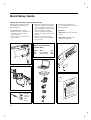
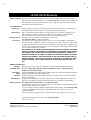
RJP-201M
Remote Jack Pack
Installation
& Setup Guide
Warranty
© Copyright 2010, LG Electronics U.S.A., Inc.
For Customer Support/Service, please call: 1-888-865-3026
www.lgsolutions.com
The exclamation point within an equilateral triangle is intended to alert the user to the presence
of important operating and maintenance (servicing) instructions in the literature accompanying
the appliance.
CAUTION:
TO REDUCE THE RISK OF ELECTRIC SHOCK - - USE ONLY INDOORS
ATTENTION:
RISQUE DE CHOCS ÉLECTRIQUE - - POUR INSTALLATION À L¡¯INTÉRIEUR SEULEMENT
WARNING:
TO PREVENT FIRE OR SHOCK HAZARDS, DO NOT EXPOSE THIS PRODUCT TO RAIN OR MOISTURE.
Apparatus shall not be exposed to dripping or splashing and no objects filled with liquids, such as
vases, shall be placed on the apparatus.
AVERTISSEMENT:
L’appareil ne doit pas être exposé à des égouttements d’eau ou des éclaboussures et de plus
qu’aucun objet rempli de liquide tel que des vases ne doit être placé sur l’appareil.
REGULATORY INFORMATION:
This equipment has been tested and found to comply with the limits for a Class B digital device, pursuant to Part 15 of the FCC Rules. These limits are designed to provide reasonable protection against
harmful interference when the equipment is operated in a residential installation. This equipment
generates, uses and can radiate radio frequency energy and, if not installed and used in accordance
with the instruction manual, may cause harmful interference to radio communications. However, there
is no guarantee that interference will not occur in a particular installation. If this equipment does
cause harmful interference to radio or television reception, which can be determined by turning the
equipment off and on, the user is encouraged to try to correct the interference by one or more of the
following measures:
• Reorient or relocate the receiving antenna.
• Increase the separation between the equipment and receiver.
• Connect the equipment into an outlet on a circuit different from that to which the receiver
is connected.
• Consult the dealer or an experienced radio/TV technician for help.
CAUTION:
Do not attempt to modify this product in any way (except as noted herein) without written authorization from LG Electronics U.S.A., Inc. Unauthorized modification could void the user’s authority to
operate this product.
COMPLIANCE:
The responsible party for this product’s compliance is:
LG Electronics U.S.A., Inc., 2000 Millbrook Drive
Lincolnshire, IL 60069, USA • Phone: 1-847-941-8000.
Marketed and Distributed in the United States by LG Electronics U.S.A., Inc.
2000 Millbrook Drive, Lincolnshire, IL 60069
2
© Copyright 2010, LG Electronics U.S.A., Inc.
Table of Contents
Safety Warnings . . . . . . . . . . . . . . . . . . . . . . . . . . . . . . . . . . . . . . . . . . . . . . . 2
Table of Contents . . . . . . . . . . . . . . . . . . . . . . . . . . . . . . . . . . . . . . . . . . . . . . 3
Overview . . . . . . . . . . . . . . . . . . . . . . . . . . . . . . . . . . . . . . . . . . . . . . . . . . 4-5
Accessories . . . . . . . . . . . . . . . . . . . . . . . . . . . . . . . . . . . . . . . . . . . . . . . . .6-7
Installation
Installation in Cabinet Backsplash . . . . . . . . . . . . . . . . . . . . . . . . . . . . . . . . . . . 8
Installer Connections . . . . . . . . . . . . . . . . . . . . . . . . . . . . . . . . . . . . . . . . . . . . 9
Installation Mixed Signal Breakout Cable . . . . . . . . . . . . . . . . . . . . . . . . . . . . . . .10
Connections to TV Display Panel . . . . . . . . . . . . . . . . . . . . . . . . . . . . . . . . . . . . 11
End-User Operation
End-User Connections Overview . . . . . . . . . . . . . . . . . . . . . . . . . . . . . . . . . . . . .12
End-User Multi-Media Interface Connections . . . . . . . . . . . . . . . . . . . . . . . . . . . . 13
End-User Connectable External Source Devices . . . . . . . . . . . . . . . . . . . . . . . . . . . 14
Specifications . . . . . . . . . . . . . . . . . . . . . . . . . . . . . . . . . . . . . . . . . . . . . 15-16
Troubleshooting
Troubleshooting . . . . . . . . . . . . . . . . . . . . . . . . . . . . . . . . . . . . . . . . . . . . . . 17
Troubleshooting Flow Chart . . . . . . . . . . . . . . . . . . . . . . . . . . . . . . . . . . . . . . . 18
RJP-201M Scaler RJP Supported Timing List . . . . . . . . . . . . . . . . . . . . . . . . . . . . 19
Quick Setup Guide . . . . . . . . . . . . . . . . . . . . . . . . . . . . . . . . . . . . . . . . . . . .20
Warranty . . . . . . . . . . . . . . . . . . . . . . . . . . . . . . . . . . . . . . . . . . . . . . Back Cover
3
Overview
The Remote Jack Pack (RJP) contains circuitry to determine the presence of a signal at each input jack.
(Note: Audio In, Audio In L-R and Video In inputs detect the presence of the inserted plug, regardless if a signal is present or not.)
When a source is detected, its priority is compared to the priority of
other sources which may be present. If the newly-connected active
source is of higher priority than the existing source(s), the RJP
directs the TV display panel to that source.
Video and audio are monitored and switched independently.
Power is supplied to the RJP by the TV display panel via the control
signal cable.
4
Overview
CLEANING CAUTION:
Since the end-user jack panel is exposed, use extreme caution when
cleaning. Do not use liquid cleaners on the connection panel. Do
not allow liquids to be spilled, sprayed onto or otherwise come into
contact with the connection panel on either the end-user side or
the installer side. Clean with a slightly damp cloth.
7 AMPS MAXIMUM CURRENT FOR THE AC OUTLETS:
The maximum combined total current that is allowable to the four
AC power outlets is 7 Amps. These are protected by a circuit breaker
type re-settable fuse.
Introduction
Conveniently installed right in the room where guests will stay, the LG Remote
Jack Pack, (RJP) multi-media interface is available to end-users to connect audio,
video and computer devices to hear and view on the in-room TV display panel.
The RJP can be set up to interface with the TV display panel to show the image
and/or sound from a portable DVD/CD Player, Camcorder, MP-3 Player, Notebook
computer, or portable Video Game Player. Or, devices with digital video output
such as DVD players. A USB connection is available for future applications. If the
end-user does not connect any devices, then the in-room TV display panel will
remain on the source selected. When the end-user connects a device, the interface switches the TV display panel to the new source. Users can recharge laptop
or cell phone batteries while watching TV.
The RJP interface is designed to be able to process audio from one source, and
video separately from a different source, if required. (The end-user can work on a
laptop computer while listening to music from an MP-3 player.) However, only
one audio and one video source can be heard/seen at the same time.
The end-user can simply plug the device’s power cord into one of the four convenience AC power outlets provided on the RJP. Then plug in its Audio/Video
cable(s) to the RJP input jack(s) and turn the device on. The RJP completes the
connection between the newly-connected audio and/or video source and the TV
display panel. No end-user menus are involved, all connections are made directly
to the interface.
The RJP continually monitors its source inputs. When a signal is detected, (a
device is plugged into one of the RJP inputs) the interface sends a message to
the TV display panel to switch to the newly-connected source (if the new source
is of higher priority). The interface allows only the higher priority audio and
video to be heard and seen on the TV display panel. The control cable supplies
12 Volt DC power from the TV display panel to operate the interface.
5
Accessories
Supplied Accessories
Ensure that the following accessories are included with your product.
Mixed Signal Cable Assembly
Installation & Setup Guide
Network Cable (8-Pin RJ-45)
w/Black Protective Sleeve
(approx.6.0 feet)
6-Pin RJ-11 Phone Cable
(approx.6.0 feet)
5-Retainer Clips, L-Shaped
5-Machine Screws w/Serrated
Washers
6
Mixed Signal Breakout Cable
Mixed Signal In
Mixed
Item
No.
1.
2.
3.
Gender Cable
Assembly
approx.
12.9
Feet
in
Length
1.
Audio Cable
(L - R)
2.
Digital Video
Cable
Signal Breakout Cable
Description
Audio Cable (Left/Right)
Digital Video Cable
Control Cable (8-pin RJ-45)
3.
Control
Cable
Note: The actual appearance of the cable, cabinet, mounting hardware etc., may be different than shown in
these drawings.
7
Installation in Cabinet Backsplash
The RJP-201M can only be installed in a vertical position
into the backsplash of the cabinet. Vertical mounting in the
backsplash is required so that if liquid is spilled on the desk
top, it will not be able to flow into the RJP. The RJP must
only be installed in the backsplash panel cutout opening. It will then
need to be secured with the four retainer clips, serrated washers and
machine screws provided. The cable wiring assembly and individual
cables will need to be connected to the RJP. All cables will need to
be threaded along the backside of the backsplash panel through the
TV wiring cutout to the TV and other in-room resources.
Note: The connector set that is closest to the mesh sleeving is for
hook up to the TV display panel.
(4-Screws)
Installation Instructions
1. Remove the cabinet backsplash and insert the RJP into the cutout
opening.
2. Install the faour L-shaped mounting retainer clips, screws and
serrated washers provided to hold the RJP securely in place. Check
to assure that the RJP is securely mounted.
3. Make all connections to the RJP, please see the following page for
details.
4. After attaching cable hardware etc., reinstall backsplash on the
cabinet.
CAUTION: The cable wiring assembly should be handled
carefully to avoid damage, as it is fed through the opening
and attached to the RJP. The cable assembly needs to be
looped down into the area provided and then threaded
along the channel in the backside of the backsplash to the TV wiring
cutout in the cabinet. The AC power cord should be plugged into a
dedicated and appropriate AC wall power outlet.
Note: The actual appearance of the
cable assembly, cabinet, backsplash,
mounting hardware and cable
clamps etc., may be different than
shown in these drawings.
8
Installer Connections
The RJP-201M and the cables listed below are to be connected to both the TV display panel
and any entertainment resources available in the room.
CAUTION: Be sure power is turned off before attempting to connect the RJP-201M to the
TV display panel and in-room resources.
MIXED SIGNAL NETWORK PHONE
OUT
OUT
OUT
MIXED SIGNAL NETWORK PHONE
OUT
OUT
OUT
Mixed Signal Cable
Mixed Signal Cable from Mixed
Signal Breakout Cable assembly
must connect to Mixed Signal Out
Connector.
Otherwise damage will occur.
Network Port (8-Pin RJ-45)
Connect to LAN wall jack, if available. Allows the end-user to access
the LAN (local area network) server of the institution.
Phone Port (6-Pin RJ-11)
Connect to telephone line wall jack. Allows the end-user, using a
computer modem, to connect to their ISP (Internet Service
Provider) to access the Internet through a local phone line.
AC Power Cord (Installed on RJP)
Connect to standard 120V 60Hz AC power outlet.
(Four 120 Volt 60 Hz AC power outlets are provided for
the end user.
However, 7 Amps. is the maximum combined current
allowed for the AC outlets.)
AC Power Cord
Connect to 120V 60 Hz AC
power outlet. Supplies
power to the four convenience AC power outlets for
end-user. (Maximum combined total current allowed
is 7 Amps.)
6-Pin RJ-11 Phone Cable
Connect to telephone line
wall jack panel.
Network Cable (8-Pin RJ45) w/Black Protective
Sleeve
Connect to LAN wall jack
panel.
9
Installation Mixed Signal Breakout Cable
CAUTION: Be sure power is turned off before attempting to connect the RJP to the TV display
panel.
1. Take off the two-sided tape that is
attached to the Mixed Signal Breakout
cable.
2. Attach the Mixed Signal Breakout cable
to TV display panel on the back.
3. Connect the Mixed Signal Breakout
cable to the TV display panel.
Note : The actual appearance of the cable, cabinet, hardware etc., may be different than shown in these
drawings.
10
Connections to TV Display Panel
After completing connections between the RJP and the TV display panel, be sure the installer menu items have
been updated to enable the RJP. Installer Menu item 040 Auto Camport needs to be set to 000 and 093 RJP
Available needs to be set to 005 or 006.
(See TV installation guide for complete instructions on new TV installations.) A brief description of each of the
available RJP connections is provided below.
Network Port (8-Pin RJ-45)
Connect to LAN wall jack, if available. Allows the end-user to
access the LAN (local area network) server of the institution.
Phone Port (6-Pin RJ-11)
Connect to telephone line wall jack. Allows the end-user, using a
computer modem, to connect to their ISP (Internet Service
Provider) to access the Internet through a local phone line.
AC Power Cord (Installed on RJP)
Connect to standard 120V 60Hz AC power outlet.
(Four 120 Volt 60 Hz AC power outlets are provided for
the end user.
However, 7 Amps. is the maximum combined current
allowed for the AC outlets.)
AV IN 1
VIDEO
AUDIO
RESET
UPDATE
RGB IN (PC)
L(MONO) R
RJP
2
L
VIDEO
AUDIO IN
R
AUDIO
1
(RGB/DVI)
COMPONENT IN
/DVI IN
SPEAKER OUT REMOTE
(8 )
CONTROL OUT
RS-232C IN
(SERVICE ONLY)
Digital Video
Cable
Audio Cable
(L-R)
Control
Cable
Power Cord
Note:
- The actual appearance of the TV display panel
connections etc., may be different than shown
in this drawing.
- Installer Menu Item 093 RJP Available
(HDMI) for HDMI set to
(Digital video & Audio) for DVI set to
6-Pin RJ-11
Phone Cable
Network Cable
(8-Pin RJ-45)
w/Black
Protective
Sleeve
005
006
- TV/STB Installer Menu Item 093 RJP Available must have options 005 and 006 to be compatible.
Be sure to make all RJP connections before setting installer items.
11
End-User Connections Overview
The end-user simply plugs a device such as a laptop computer with the appropriate cables, as shown in the
example, into the RJP connection panel. The Remote Jack Pack senses the new source connection and
switches the TV to the newly-connected source. The device’s sound and image are then presented on the inroom TV display panel. The TV display panel adjusts automatically to the computer output format.
When the laptop is disconnected, the interface directs the TV to revert back to the previous source for video
and audio.
The end-user has several audio/video connection options available for connecting external devices. The
guest/user can connect a portable DVD Player, CD Player, Camcorder, MP-3 Player, Notebook Computer,
Portable Video Game Player, etc. For added convenience, four AC power outlets are also available on the front
of the interface to provide power for these external devices and/or recharge laptop or cell phone batteries.
(The maximum combined current allowed for the AC power outlets is 7 Amps.)
An end-user could connect and hear audio from one device and connect and view video from a different
device. The RJP offers two different stereo audio input jacks to accommodate various end-user devices.
However, only the higher priority audio source will be selected and heard. Similarly, multiple video inputs are
available, but only the higher priority video source will be selected and displayed.
(See page 12 input priorities.)
Typical
In-Room TV
Display Panel
S TO RES
ES
ET
PR
Today's
Report
DIGITAL VIDEO IN
CHARGE
PHONE IN NETWORK IN
10 AMP MAXIMUM CURRENT
SYNC
PC VIDEO IN
AUDIO IN
L-AUDIO IN-R VIDEO IN
End-User
Connection Panel
CHARGE
s
Today'
Report
SYNC
IN
VIDEO
IN
DIGITAL
AUDIO
IN
PC
VIDEO
IN
VIDEO
IN-R
®
L-AUDIO
IN
IN
TO RESE
T
PR
E
PHONE
SS
T
10
12
AMP
M CURREN
MAXIMU
NETWORK
End-User Multi-Media Interface Connections
USB Charging Port
Connection for USB
device charging.
USB Sync Port
Connection for playing
multi-media file.
S TO RES
ES
ET
PR
Reset Switch
Circuit breaker for
AC power outlets.
DIGITAL VIDEO IN
CHARGE
PHONE IN NETWORK IN
SYNC
10 AMP MAXIMUM CURRENT
PC VIDEO IN
AUDIO IN
VIDEO IN L-AUDIO IN-R
3.5 mm Stereo
Audio Input Jack
Connection for MP-3
player or PC audio.
AC Power Outlets
Four (4) convenience AC outlets
for end-user. (Total combined
current is 7 Amps maximum.)
Video/Audio Input Jacks
Connection for composite
Video/Left-Right Audio
sources.
Phone In (RJ-11) Jack
Access to room’s phone line (PC
Modem).
Network In (RJ-45) Jack
Port for access to institution’s
local area network server, if
available.
Digital Video Input Port
Connection for digital video
sources. (portable DVD)
PC Video (RGB) Input Port
Connection for PC Video.
End-User Audio/Video Input Priorities
Note: The highest priority is listed first.
Video Inputs
Direct Connections to In-Room Resources
1st.
2nd.
3rd.
4th.
5th.
A.
B.
C.
Digital Video
PC Video
S-Video
Video Composite Jack
TV Display Panel Tuner Video (Video Default)
USB (if available)
LAN RJ-45
Phone RJ-11
Audio Inputs/Sources
1st.
2nd.
3rd.
4th.
3.5 mm Stereo Audio Jack
Left - Right Audio Jacks
Digital Video Audio
TV Display Panel Tuner Audio (Audio Default)
Note: Audio In, Audio In L-R and Video In inputs detect the presence of the inserted plug, regardless if a signal is present or not.
13
End-User Connectable External Source Devices
Examples of devices a guest/end-user
can connect are shown to the right.
There are four AC power outlets
available on the jack pack for added
convenience.
The End-User Can Connect:
• PC Laptop/Notebook Computers
• Portable Video Game Players
• Portable DVD/CD Players
• Camcorders
• Digital Cameras
• MP-3 Audio Players
• USB Flash Drives
and other USB devices
(if available)
14
Specifications
Application
Makes available to the hotel’s guests, a multi-media interface to the in-room TV display panel and media
resources. Input jacks are provided for external portable devices such as DVD/CD Players, Laptop
Computers, Camcorders, etc.
Dimensions
Height
Width
Depth
Weight (Approx.)
4.08 Inches
16.49 Inches
2.18 Inches
2.54 Pounds
(103.6 mm)
(418.95 mm)
(55.4 mm)
(1.15 kg)
End-User Device Inputs
AC Outlets x 4
Phone In
Network In
Audio In
Audio In L-R
Video In
PC Video In
Digital Video In
USB In
AC 120V 60Hz (Maximum 7 Amps.
total combined current allowed for AC outlets)
Phone Jack (6-Pin RJ-11)
LAN Jack (8-Pin RJ-45)
3.5 mm Stereo Audio Jack
Left - Right Audio Jacks
(Nom In: 250mV RMS @ 22K ohms)
Overload In: 1.6V RMS Max
Composite Video Jack
1 Vpp, 75 ohms
15-pin RGB PC Monitor Connector
Digital Video Connector
USB Connector (“A”-type female)
Installer Connections
(RJP Back)
Network Out
Phone Out
(TV Display Back)
Mixed Signal Breakout
Cable
LAN Jack (8-Pin RJ-45)
Phone Jack (6-Pin RJ-11)
• Digital Video Cable
• Audio L-R
• Control Cable (8-pin RJ-45)
15
Specifications
Regulatory
UL, FCC
Class B, Digital Video Device
Environmental Parameters
Operating Temperature
0° to 40° Degrees Celsius
(32° to 104° Degrees Fahrenheit)
Storage Temperature
-20° to 85° Degrees Celsius
(-4° to 185° Degrees Fahrenheit)
Cooling
Humidity
Free Air Convection
10% to 90% Non-condensing
Supplied Accessories List
(Cable Assembly)
• Mixed Signal Cable Assembly (approx.12.9 ft)
(Separate Cables)
• Phone Cable (6-Pin RJ-11)
• Network Cable (8-Pin RJ-45)
(Attached Cable)
• AC Power Cord, 120V 60Hz
(Misc. Hardware)
• 5-Retainer Clips, L-Shaped (4-Required)
• 5-Machine Screws w/Serrated Washers (4-Required)
Note: Design and specifications are subject to change without prior notice.
16
Troubleshooting
Equipment Setup Analysis Notes
• RJP USB port is a pass-through connection, reserved for future applications.
• Make sure all connectors and connections are tight and secure on user device, RJP-201M and TV.
• Check to assure user device, RJP-201M and TV are all powered up and working properly and that the TV
Installer menu items are set correctly.
• Check to assure network interface to host is viable and working.
• Audio and Video can be from different sources. Default is TV tuner Audio and Video, if no other
audio/video source is connected.
• Audio source must be viable. The audio output from the customer’s device must be present when connected
to be heard at the TV.
• RJP AC circuit breaker maximum is 7 Amps. If 7 Amp current limit is exceeded, breaker will trip; unplug all
accessory devices from RJP AC outlets and press RESET.
Test Procedures
• Test and connect only one user device to determine if RJP is providing audio/video to TV.
• Test user device on another RJP (perhaps located in a different room) to determine if user device is com-
patible with RJP.
• On LCD or Plasma TVs, be sure Installer menu item 040 is set to 000 and 093 is set to 001 to enable RJP
mode.
Following are some possible solutions to problems:
Problem
Possible Cause(s) Check RJP, User Device and In-Room TV
No Power
• Power not connected?
• Circuit breaker on RJP tripped?
(Unplug all accessory devices from RJP AC outlets, press RESET.)
No Audio
•
•
•
•
•
•
•
Have all audio connections been made?
Audio output available?
Volume level turned up?
Sound muted?
TV setup correct for RJP? (Installer menu item 040 is set to 000 and 093 set to 001.)
Try another RJP.
Priority level? (Disconnect other devices.)
No Video
•
•
•
•
Video output available?
All video cables connected?
TV setup correct for RJP? (Installer menu item 040 is set to 000 and 093 set to 001.)
Priority level? (Disconnect other devices.)
Poor Video
• Check connections. (Video pass-through no user action possible.)
USB
No USB
function
• USB connected?
• RJP USB port is a pass-through, no action possible.
17
Troubleshooting Flow Charts
No
Power
Power
Failure?
Yes
Restore
Power
RJP
Has Circuit
Breaker
Tripped
?
Yes
Remove AC
load, press
RESET
RJP
Has Circuit
Breaker
Tripped
?
No
Connect
Power
Cord
RJP
Is Audio
connected
?
No
Connect
Audio
Cables
RJP
Is Video
connected
?
Yes
Yes
Remove AC
load, press
RESET
No
RJP
Are other
audio devices
connected
?
Yes
Disconnect
other
Audio devices
RJP
Are other
Video devices
connected
?
No
Connect
Power
Cord
Yes
TV
Is TV
turned
On
?
No
Turn
TV On
TV
Are
Speakers
turned Off
?
No
TV
Is TV
turned
On
?
Yes
Turn
Speakers
On
User
Device
Is correct
Video output
selected
?
No
Select
correct Video
output
PC
External
Port
Yes
No
Turn
Power
On
TV
Is sound
Muted
or set too
low
?
Yes
Press
Volume
Up
No
User
Device
Is Audio
connected
?
No
Connect
Yes
User
Device
Audio
available &
turned up
?
18
Turn
TV On
Are
Installer menu
items set up?
User
Device
Is Video
connected
?
Yes
Yes
No
No
Connect
Power
Cord
Yes
User
Device
Is device
turned On
?
Disconnect
other
Video devices
Turn
Power
On
Yes
User
Device
Is power cord
connected
?
Yes
Are
Installer menu
items set up?
No
Connect
Video
Cables
Yes
Yes
TV
Is TV power
turned on
?
No
No
No
TV
Is power cord
connected
?
Remove AC
load, press
RESET
Yes
Yes
RJP
Has Circuit
Breaker
Tripped
?
Yes
No
No
No
RJP
Is power cord
connected
?
No Audio (or
not desired
Audio)
No Audio (or
not desired
Audio)
No
Turn
Volume
Up
No
Connect
RJP-201M Scaler RJP Supported Timing List
1. Input
2. Output
Format
(Pixels x Lines)
Video Input
1
640x350@70
RGB/HDMI(DVI)
2
[email protected]
RGB/HDMI(DVI)
3
640x400@85
4
Format
(Pixels x Lines)
Video Output
Comments
1
800x600@60
HDMI(DVI)
Installer Menu only
2
1360x768@60
HDMI(DVI)
Shipping Default
RGB/HDMI(DVI)
3
1680x1050@60
HDMI(DVI)
Future Using
[email protected]
RGB/HDMI(DVI)
4
1920x1080@60(RB)
HDMI(DVI)
Future Using
5
720x400@70
RGB/HDMI(DVI)
6
640x480@60
RGB/HDMI(DVI)
7
640x480@66
RGB/HDMI(DVI)
8
640x480@72
RGB/HDMI(DVI)
No
9
640x480@75
RGB/HDMI(DVI)
10
800x600@56
RGB/HDMI(DVI)
11
800x600@60
RGB/HDMI(DVI)
12
800x600@72
RGB/HDMI(DVI)
13
800x600@75
RGB/HDMI(DVI)
14
832x624@75
RGB/HDMI(DVI)
15
1024x768@60
RGB/HDMI(DVI)
16
1024x768@70
RGB/HDMI(DVI)
17
1024x768@75
RGB/HDMI(DVI)
18
1280x960@60
RGB/HDMI(DVI)
19
1280x960@75
RGB/HDMI(DVI)
20
1280x1024@60
RGB/HDMI(DVI)
21
1280x1024@75
RGB/HDMI(DVI)
22
1360x768@60
RGB/HDMI(DVI)
23
1360x768@75
RGB/HDMI(DVI)
24
1400x1050@60
RGB/HDMI(DVI)
25
1400x1050@75
RGB/HDMI(DVI)
26
1600x1200@60
RGB/HDMI(DVI)
27
1680x1050@60
RGB/HDMI(DVI)
28
1920x1080@60
RGB/HDMI(DVI)
29
480i
CVBS/HDMI(DVI)
30
480p
RGB/HDMI(DVI)
31
576i
CVBS/HDMI(DVI)
32
576p
RGB/HDMI(DVI)
33
720p50
RGB/HDMI(DVI)
34
720p60
RGB/HDMI(DVI)
35
1080i50
HDMI(DVI)
36
1080i60
HDMI(DVI)
37
1080p24
HDMI
38
1080p25
HDMI
39
1080p30
HDMI
40
1080p50
RGB/HDMI(DVI)
41
1080p60
RGB/HDMI(DVI)
Comments
No
19
Quick Setup Guide
Installer RJP-201M Quick Setup Reference Guide
Following are the tasks associated
with installing and setting up an
RJP-201M System.
1. Install RJP-201M in cabinet.
2. Make all hard wire connections to
RJP-201M, TV and any other
inroom resources.
3. Plug all system components into
power sources.
4. Adjust TV installer menu items 040
and 093 to enable RJP capability.
(See TV installation guide for complete instructions on new TV installations. The master TV setup
can be modified to include RJP
settings for multiple system installations.)
5. Test the system with user-type
devices to assure TV sound/picture
are as desired.
6. Provide user information in
room. (As applicable to your entertainment system.)
Suggestions
• RJP-201M Tent Card. (Or equiv-
alent)
• RJP-201M Quick Reference
Guide. (Or equivalent)
Typical TV Display Panel
Installer Menu
Item
040
093
Desc.
Auto Camport
RJP Available
Set
000
001
RJ
P-2
01
M
Re
mo
te
J
ee
k (S
ac
kP
ac
er
oth
e
sid
)
AV IN 1
VIDEO
AUDIO
RESET
RGB IN (PC)
L(MONO) R
UPDATE
RJP
2
L
VIDEO
AUDIO IN
R
AUDIO
1
(RGB/DVI)
COMPONENT IN
/DVI IN
SPEAKER OUT REMOTE
(8 )
CONTROL OUT
RS-232C IN
(SERVICE ONLY)
e
rfac
Inte ide
u
dia
i-Me ce G
Mult eferen
R
k
Quic
tel.
s ho
at thi
ilable
be ava
not
may .
ble
ove
wn ab availa
ns sho s are
optio resource
ction what
ne
con
firm
d PC
k
media to con
eo an
multi- hotel
e
Pac
, vid
All the with the
Jack terfac rsonal audio
Note: check
ote edia In
pe
r,
Please
ect panel.
orde
Rem
i-M
conn lay
-M
Camc
yer, devices
Mult ovided to TV/disp
-201
CD Pla nt
RJP l Guest
is pr in-room
DVD/ rtainme
e
Pack
rtable r ente
Hote mote Jack view on th
t a po othe
Re ar and
her
nnec yer and .
or ot The
e LG
n co
• Th es to he
d.
kers
u ca Game Pla watch TV
e ma ovide
t, yo
d
devic
coffe tlets pr
e lef , Video etc. an
,
th
ns
PC
iro wer ou
n on ptop laptop
ing
La
e,
show
cloth AC po
• As Player, ll phon
yers, the four
MP-3 your ce
ir dr
e
e
t ha es to ps.
Gam
hine
nnec ic devic 10 Am
charg
Mac
t co
is
ts.
e.
Do no nt electr outlets
outle interfac e. For
.
rre
ur
ION:
ia
vic
ur AC
ce
e fo lti-med ent de laptop PC
CAUT r high-cu for all fo
terfa of th
fer
d
simila um loa
ia In o one to the mum a dif on your laptop
ed
DVD
your me
lti-M rd int tput
eo fro work
maxim
er
Play
e Mu power co ideo ou w vid ile you displays the sa
m
e th
/v
d vie yer wh r and
o fro
to Us vice’s audio e an
How your de vice’s e devic MP-3 pla -3 playe dio/vide
de
au
g
on
MP
e
ur
y
• Plu ect th
from n to yo m your typicall
er
cord
dio
.)
nn
Cam
• Co n to au can liste und fro , more ections
so
Or
te
• Lis ple you plays screen. able conn
is
exam -room TV e TV’s r avail
th
fo
limit in
tal
this rs, sim
The age on her side
Digi
era
. If
cu
im
Cam
Amps this oc
PC’s (See ot
e.
at 10 . If
it.
devic
rated rned offet the un
is
tu
er
res
is
MP3
break wer
and
er
Play
cuit d AC po power
cir
hableps up an tate AC
h
ns
switc
Flas
The tton po n to rei
Drive
ITCH: SET bu T butto
RE
T SW
SE
RESE ed, the e red RE
ed
exce sh in th
ply pu
PC
Standard
120 Volt
60Hz AC
Power
Outlet
20
Memo
21
Memo
22
Memo
23
LG RJP-201M Warranty
Remote Jack Pack Welcome to the LG family! We believe that you will be pleased with your new LG product.
Please read this warranty carefully, it is a “LIMITED WARRANTY” as defined under Federal Law.
This warranty gives you specific legal rights, and you may also have other rights that vary
from state-to-state within the U.S.A.
LG’S RESPONSIBILITY
Service Labor
Replacement
Warranty Service
Not Covered
During a period of one year from effective warranty date, LG will replace a defective unit, as
determined by the LG service center, as a result of manufacturing defects.
New or remanufactured replacements for factory-defective units will be supplied by an LG
authorized service center for one year from effective warranty date. Such replacement
unit is warranted for the remaining portion of the original warranty period.
Warranty service is provided in the institution in most cases.
Call 1-888-865-3026 for further information.
This warranty covers manufacturing defects and does not cover installation, adjustment of
customer controls, installation or repair of antenna systems, cable converters or cable company-supplied equipment; it also does not cover damage due to misuse, abuse, negligence, acts
of God or other causes beyond the control of LG. Any alteration of the product after manufacture voids this warranty in its entirety.
THIS WARRANTY IS IN LIEU OF ANY OTHER WARRANTY, EXPRESS OR IMPLIED, INCLUDING
WITHOUT LIMITATION, ANY WARRANTY OF MERCHANTABILITY OR FITNESS FOR A PARTICULAR PURPOSE, AND LG SHALL NOT BE LIABLE FOR ANY CONSEQUENTIAL, INDIRECT, OR
INCIDENTAL DAMAGES OF ANY KIND, INCLUDING LOST REVENUES OR PROFITS IN CONNECTION WITH THIS PRODUCT. SOME STATES DO NOT ALLOW LIMITATIONS ON HOW LONG AN
IMPLIED WARRANTY LASTS OR THE EXCLUSION OR LIMITATION OF INCIDENTAL OR CONSEQUENTIAL DAMAGES, SO THE ABOVE LIMITATIONS OR EXCLUSIONS MAY NOT APPLY TO
YOU.
OWNER’S RESPONSIBILITY
Effective
Warranty Date
Warranty begins on the date of installation of the RJP-201M Multi-Media Interface.
For your convenience, keep the dealer’s dated bill of sale or delivery ticket as
evidence of the purchase date.
Installation Read the Installation and Setup Guide carefully so that you will understand the functions of
Guide the RJP-201M and how to make adjustments.
Antenna Reception problems caused by inadequate antenna or faulty antenna connections are the
owner’s responsibility.
Audio Output Audio problems caused by inadequate audio devices or audio material with sound level
lapses are not within the control of LG and therefore are the owner’s responsibility.
Warranty Service For warranty service information, call 1-888-865-3026.
- A replacement unit that is LG’s responsibility (see above) will be provided without charge.
Other service is at the owner’s expense.
- If you have any problem in obtaining satisfactory warranty service, call 1-888-865-3026.
- You must provide the model number, serial number and date of purchase or date of
original installation.
- Before you ask for warranty service, reread this guide. You might avoid a service call.
For Customer Support/Service please call: 1-888-865-3026
www.lgsolutions.com
LG Electronics U.S.A., Inc.
2000 Millbrook Drive, Lincolnshire, IL 60069
P/NO : 3350GDKM013?A
GPN10MA017B