1
3A0-602413-363
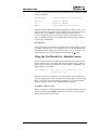
These timer registers are processed as parallel feedback just as an absolute
encoder would be. Using the Executive program Encoder Table Configure
window, you select the Parallel Y Data with Filtering conversion method. If
writing directly to the table, this is the $30 format. The source address is the
address of the appropriate timer as shown above ($C000, $C008, etc.)
Bits Enabled: Entry Second Line
The second line of the conversion table entry is the Bits Enabled Mask word.
This should be set to $07FFFF, specifying use of 19 bits of the timer. Note that
19
this does not necessarily limit the absolute position range to 19 bits (2 LSBs,
or 524,288 LSBs); the full range is set by the number of bits read by Ix10 at
power-up/reset; this is suggested to be 23 bits for a range of 2
8,388,608 LSBs (see below).
23
LSBs, or
Maximum Change: Entry Third Line
The third line of the conversion table entry is the Maximum Change filter value.
This value, expressed in bits per servo cycle, specifies the maximum change in
the source data that will be accepted as real. This is an important protection
against extra or missing return pulses. It should be set to a value slightly greater
than the maximum real velocity expected in the application.
Table Result Register
The result of this conversion is in the X-register of the last (third) line of the
entry. Any function using this value should address this register. For example,
if this were the first entry in the table, which starts at $0720, the result would be
in X:$0722.
Example
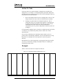
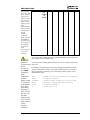
To set up the encoder conversion table to process MLDTs on Channels 1 to 8
only, with a maximum change per servo cycle of 32 LSBs per servo cycle, the
following direct memory write commands could be used:
WY:$0720,$30C000,$07FFFF,32
WY:$0723,$30C008,$07FFFF,32
WY:$0726,$30C010,$07FFFF,32
WY:$0729,$30C018,$07FFFF,32
WY:$072C,$30C000,$07FFFF,32
WY:$072F,$30C008,$07FFFF,32
WY:$0732,$30C010,$07FFFF,32
WY:$0735,$30C018,$07FFFF,32
;
;
;
;
;
;
;
;
Parallel
Parallel
Parallel
Parallel
Parallel
Parallel
Parallel
Parallel
read
read
read
read
read
read
read
read
of
of
of
of
of
of
of
of
Timer
Timer
Timer
Timer
Timer
Timer
Timer
Timer
1
2
3
4
5
6
7
8
The resulting values from these conversions are in the following registers:
Channel 1
X:$0722
Channel 2
X:$0725
PMAC2 User’s Manual – 15 March 1997
10-7