1
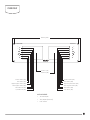
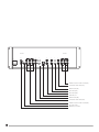
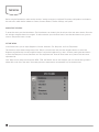
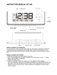
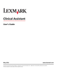
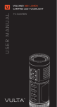
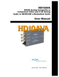
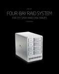
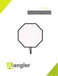
IN
SRM-7X2-LT
S
STUDIOVISION
SRM-7X2-LT
Dual 7″ Rack Mount Monitors
STUDIOVISION
SRM-7X2-LT
STUDIOVISION
SRM-7X2-LT
INPUT
INPUT
MENU
MENU
ENTER
ENTER
FN
FN
1
2
2
user MANUAL
MONITOR 1
MONITOR 2
IN
TALLY
IN
IN
IN
IN
IN
VIDEO
HDMI
SDI
SDI
HDMI
VIDEO
OUT
OUT
OUT
OUT
OUT
OUT
IN
IN
TALLY
1 TALLY1 Green
2
4
6
7
8
TALLY1
TALLY1
TALLY2
TALLY2
TALLY2
Red
GND
GND
Green
Red
POWER+12V
Y
Pb
Pr
OUT
LAN IN
Y
Pb
Pr
OUT
MONITOR 1
IN
IN
IN
IN
IN
INTRODUCTION
Thank you for choosing Elvid.
The Elvid SRM-7X2-LT StudioVision is a rack-mounted dual-monitor system with advanced
features to help you optimize your images. The StudioVision is equipped with 3G-SDI, HDMI,
component video, and composite video inputs—all with loop-through—for flexible connectivity.
The dual 7″ LED panels’ native resolution is 1280 × 800, and you can set the aspect ratio to full
screen (16:10), 16:9, 4:3, 1.85:1, and 2.35:1.
The StudioVision incorporates broadcast-specific features like underscan, safety-frame markers,
H/V delay, and a tally connector. It’s also equipped with a false color display to provide visual
guidance for achieving precise exposure levels. The StudioVision is easy to customize. Choose
from a palette of 12 functions from which you can set the function button to provide a shortcut
for enabling modes and onscreen tools. An Ethernet connection, intended for advanced users,
provides optional software control.
PRECAUTIONS
2
•
Please read and follow these instructions and keep this manual in a safe place.
•
Keep this product away from water and any flammable gases or liquids.
•
Use only the correct, recommended voltage.
•
Do not attempt to disassemble or repair this product.
•
Do not place or store the StudioVision facedown, since this can damage the screens.
•
Handle this product with care. Avoid any unnecessary impacts to this product.
•
Do not block the vents in this product.
•
Disconnect this product from its power source before storage and during electrical storms.
•
Do not use chemical solutions to clean this product. Clean it with only a soft, dry cloth.
•
Keep this product away from children.
•
Make sure that this product is intact and that there are no missing parts.
•
To avoid damage to this product, be careful not to overtighten or improperly thread any of the
threaded fittings.
•
All photos are for illustrative purposes only.
OVERVIEW
Mounting holes
STUDIOVISION
SRM-7X2-LT
STUDIOVISION
SRM-7X2-LT
INPUT
INPUT
MENU
MENU
ENTER
ENTER
FN
FN
2
1
Monitor 1 (M1)
MONITOR 2
MONITOR 1
Monitor 2 (M2)
IN
IN
IN
IN
IN
VIDEO
HDMI
SDI
SDI
HDMI
VIDEO
OUT
OUT
OUT
OUT
OUT
OUT
IN
TALLY
IN
IN
TALLY
1 TALLY1 Green
2
4
6
7
8
TALLY1
TALLY1
TALLY2
TALLY2
TALLY2
Red
GND
GND
Green
Red
Function button (M1)
POWER+12V
Y
Pb
OUT
Pr
LAN IN
Y
Pb
Pr
Function button (M2)
OUT
Enter button (M2)
Enter button (M1)
Right navigation button (M1)
Right navigation button (M2)
Left navigation button (M1)
Menu button for(M1)
Left navigation button (M2)
Menu button (M2)
Input button (M2)
Input button for(M1)
ALSO INCLUDED
•
12 V DC adapter
•
Tally adapter (bare-end)
•
User manual
3
STUDIOVISION
SRM-7X2-LT
STUDIOVISION
SRM-7X2-LT
INPUT
INPUT
MENU
MENU
ENTER
ENTER
FN
FN
2
1
MONITOR 1
MONITOR 2
IN
TALLY
IN
IN
IN
IN
IN
VIDEO
HDMI
SDI
SDI
HDMI
VIDEO
OUT
OUT
OUT
OUT
OUT
OUT
IN
IN
TALLY
1 TALLY1 Green
2
4
6
7
8
TALLY1
TALLY1
TALLY2
TALLY2
TALLY2
Red
GND
GND
Green
Red
POWER+12V
Y
Pb
OUT
Pr
LAN IN
Y
Pb
Pr
OUT
YPbPr component video in/out (M1)
Composite video in/out (M1)
HDMI in/out (M1)
SDI in/out (M1)
SDI in/out (M2)
Ethernet port
HDMI in/out (M2)
Composite video in/out (M2)
YPbPr component video in/out (M2)
DC power input
DB15 tally connector
4
MENU
GETTING
STARTED
POWERING THE STUDIOVISION
To power the StudioVision, use the ENTER
included 12 V DC adapter to connect the StudioVision’s DC power input to your AC power
source.
FN
MOUNTING THE STUDIOVISION
Important!
1
Make sure your rack can support the StudioVision.
The StudioVision is designed for rack-mounted use. Use rack screws to install the StudioVision to your rack system via the unit’s
four screw-holes. Make sure the assembly is secure before proceeding.
CONNECTING TO YOUR VIDEO SOURCE
To connect the StudioVision to your video source, follow these steps:
1. Choose the appropriate cable to connect your video source to the corresponding input connections on the back of the monitor.
Make sure the input corresponds to the monitor you are using.
2. Press the Input button repeatedly until the correct input appears on the monitor.
Loop Through: The StudioVision offers video loop-through (also known as pass-through). To loop the video signal through the
monitor, make sure your video source is connected to the video input, and then connect the appropriate cable to the corresponding
output connection on the back of the monitor. For example, if you’re using the SDI input, you would use the SDI output connection
for video loop-through.
MONITOR 2
TALLY CONNECTION
If desired, connect your tally cable to the StudioVision’s DB15 tally connector or the included bare-end adapter. Refer to the
diagram in this manual for the specific tally pin connections.
IN
TALLY
IN
TALLY
1 TALLY1 Green
2
4
6
7
8
TALLY1
TALLY1
TALLY2
TALLY2
TALLY2
Red
GND
GND
Green
Red
5
10
15
4POWER+12V
3
2
1
14
9
13
8
12
7
11
Y
Pb
Pr
VIDEO
6
OUT
OUT
5
THE MENU
Before using the StudioVision, make sure the monitors’ settings are properly configured. The setting configurations are located in
the main menu, which has five submenus: Picture, Onscreen Markers, Features, Settings, and System.
NAVIGATING THE MENU
To access the menu, press the Menu button. The five submenus are located in the left column of the main menu window. Press the
left and right navigation buttons to navigate. To make a selection, press the Enter button. Press the Menu button at any point to
return to the previous menu or screen.
PICTURE MENU
In the Picture menu, you can adjust Brightness, Contrast, Saturation, Tint, Sharpness, and Color Temperature.
The shortcut to adjust these settings except Color Temp is to exit the menu and press the navigation buttons to access the
Brightness adjustment bar. Use the navigation buttons to adjust the brightness up or down. Continue pressing the Menu button
to access the Sharpness, Contrast, Saturation, and Tint adjustment bars. Press the Enter button at any time to exit the current
adjustment bar.
Color Temp: You can select from the presets 6500, 7500, and 9300 K. You can also configure your own custom setting, which is
labeled User in the Color Temp menu. Customizing the color temperature is recommended only for advanced users.
6
MARKERS MENU
Center Marker: This setting displays a marker in the center of the screen. The marker will appear onscreen after you exit the menu.
Safety Marker: You can set the StudioVision to display an onscreen box as a safety frame marker at a set percentage of the screen
size. You can set this to 95%, 93%, 90%, 88%, 85%, or 80%. The marker will appear onscreen after you exit the menu.
FEATURES MENU
Aspect Ratio: You can set the aspect ratio for the onscreen image. The options are full screen (16:10), 4:3, 16:9, 1.85:1, and 2.35:1.
Full screen will stretch the image to fill the full extent of the StudioVision’s screen, and the other options will scale the image to fit
those specific aspect ratios. The default setting is full screen.
H/V Delay: This mode is recommended only for broadcast professionals. You can set it to H, V, or H & V to display the horizontal,
vertical, or combined view of the video blanking interval.
Check Field: In Check Field mode, just the selected color will appear onscreen. You can select mono, red, green, or blue. In mono, a
gray scale image will appear onscreen. Check Field mode is useful for calibrating the monitor.
Pixel-to-Pixel: Use Pixel-to-Pixel mode to turn off scaling and display the incoming video signal in its native resolution and aspect
ratio with 1:1 pixel mapping. If the picture is larger than the monitor’s 1280 × 800 resolution, the center of the image will appear
onscreen.
Underscan: Underscan shrinks the picture so you can see the entire video image, including the area that is not broadcast-safe. You
can turn this mode on or off. The default setting is off, which displays only the broadcast-safe image.
Color Bar: Display color bars onscreen.
Zoom: Zoom into the onscreen image without altering the incoming signal or loop-through. You can choose ×2, ×4, ×6, or ×8.
Image Flip: This setting flips the image and all onscreen displays, markers, and menus horizontally, vertically, or both.
Freeze Input: Turning this setting on will freeze the current onscreen image. Any change in input, power or hitting buttons will
remove the onscreen image.
PIP: Use PIP, or picture-in-picture mode, to simultaneously display two incoming video signals on a single monitor. In the PIP Mode
submenu, you can set the size of the inset picture to small, medium, or large. You can also choose PBP to show the pictures side
by side and scaled, with scopes under and above the images; or POP to show the pictures side by side and stretched, with scopes
on top of the images. Use PIP Source to choose the source for the inset picture—SDI, HDMI, or (composite) video. Use the PIP
Position submenu to move the inset picture to different corners of the screen. PIP Swap will switch the inset and main pictures. To
deactivate PIP mode, first set the FN button to PIP (see Using the FN Button on page 8) and press it until PIP mode is turned off.
7
SETTINGS MENU
Camera: Camera mode scales the incoming video signal to fill the screen. You can set it to 480p or 1080i. This is useful when
shooting on a DSLR.
SYSTEM MENU
LOGO: Choose whether the Elvid StudioVision logo is displayed when the unit boots up.
Language: You can set the onscreen language to English or Simplified Chinese (中文).
Manufacturer Default: Restore the StudioVision to the factory default settings. This will erase all current settings and replace
them with the default settings. To do this, use the navigation buttons to highlight ON, and then press the Enter button to make a
selection.
Back Light: Adjust the brightness of the backlight from 0 to 100.
ISP: For factory use only—do not select this. If you select this, immediately reboot the StudioVision.
USING THE FN BUTTON
For greater efficiency while using the StudioVision, you can assign a unique setting to the FN (function)
button on each of the two monitors.
The options for customizing the FN button are Center Marker, Safety Marker, Check Field, Color Bar,
Aspect Ratio, Camera, PIP, Image Flip, Zoom, Pixel-to-Pixel, Freeze Input, Underscan, and H/V delay.
To customize the FN button, follow these steps:
1. Press and hold the FN button until a menu with a list of options appears on the right side of the
screen.
2. Use the left and right navigation buttons to navigate the menu and highlight the desired function.
3. Press the Enter button to select a function. The function button will remain programmed even after
the StudioVision is rebooted.
Press the Menu button at any point to return to the previous menu or screen.
8
THE ETHERNET CONNECTION
The StudioVision’s Ethernet connection is intended for software control and is recommended only for advanced users. Before using
the Ethernet connection, download and install the Elvid StudioVision software, available online at www.elvidcinema.com.
To set up the Ethernet connection, follow these steps:
1. Use an Ethernet cable to connect the StudioVision’s Ethernet port to your computer.
2. Set your computer’s IP address to 192.162.1.XXX network segment, where XXX is a user-definable parameter. Try starting with
000. For information on this topic, refer to your computer’s user manual.
To change a monitor’s settings via software, follow these steps:
1. Open the Elvid StudioVision software.
2. Select the monitor you want to adjust by clicking the corresponding button at the top of the window.
12345678
3. Change a setting by clicking the Read button to determine that setting’s current status.
4. Click the corresponding drop-down menu and select a value from it to make a change.
Bl
Br
Br
Bl
W
G
W
Bl
WG
O
WO
To exit the software, press the Exit button.
W
O
W
T568B
1 2 3 4 5 6 7 8
WO
G
WG
T568A
1 2 3 4 5 6 7 8
Bl
Br
Br
For advanced users only
SPECIFICATIONS
• Panel: Dual 7″ LED backlit (IPS) panels
• Outputs
• Native resolution: 1280 × 800 pixels
3G-SDI: ×2 (one per monitor)
• Aspect ratio: 16:10
HDMI: ×2 (one per monitor)
• Brightness: 400 cd/m²
Component video (YPrPb): ×2 (one per monitor)
• Contrast: 800:1
Composite video: ×2 (one per monitor)
• Viewing angle (H/V): 178°/178°
Current: 1500 mA
• Input voltage: 7 to 24 V DC, 1.5 A
Power consumption: ≤18 W
• Inputs
• Dimensions (L × W × D): 18.9″ × 5.3″ × 1.0″
3G-SDI: ×2 (one per monitor)
HDMI: ×2 (one per monitor)
Component video (YPrPb): ×2 (one per monitor)
Composite video: ×2 (one per monitor)
Ethernet: ×1
Tally (DB-15 connector): ×1
(48.3 × 13.4 × 2.5 cm)
• Weight: 6.4 lb. (2.9 kg)
9
SUPPORTED RESOLUTIONS AND FRAME RATES
SINGAL
MODE
SUPPORT
MODE
SUPPORT
Composite
NTSC
YES
1080p (23.98)
YES
PAL
YES
1080p (24)
YES
480i (59.94)60
YES
1080p (25)
YES
576i (50)
YES
1080p (29.97)
YES
480p (59.94)60
YES
1080p (30)
NO
576p (50)
YES
1080p (50)
YES
720p (50)
YES
1080p (59.94)
YES
720p (59.94)
NO SIGNAL
1080p (60)
YES
720p (60)
YES
1080p (23.98sF)
NO SIGNAL
1080i (50)
YES
1080p (48khz)
YES
1080i (59.94)
NO SIGNAL
2040 x 1080 (23.98sF)
NO SIGNAL
1080i (60)
YES
2040 x 1080 (24sF)
NO SIGNAL
1080p (23.98)
NO SIGNAL
2040 x 1080 (23.98p)
NO SIGNAL
1080p (24)
NO
2040 x (24p)
NO SIGNAL
1080p (25)
NO
1080p (29.97)
YPBPR
HDMI
480i (59.94)
YES
NO SIGNAL
480i (60)
YES
1080p (30)
NO
576i (50)
YES
1080p (50)
YES
480p (59.94)
NO
1080p (60)
YES
480p (60)
NO
1080p (23.98sF)
NO SIGNAL
576p (50)
NO
1080p (24sF)
NO
720p (23.98)
NO SIGNAL
480p(59.94)
(59.94)
480i
YES
(50)
720p (24)
YES
NO
480i (60)
YES
(59.94)
720p (25)
YES
576i (50)
YES
720p (60)
YES
480p (59.94)
YES
1080i (50)
YES
480p (60)
YES
1080i (59.94)
YES
576p (50)
YES
1080i (60)
YES
480p (59.94)
YES
1035i (59.94)
NO SIGNAL
480p (60)
YES
1035i (60)
NO SIGNAL
576p (50)
YES
1080p (23.976)
YES
720p (23.98)
NO
1080p (23.98)
NO SIGNAL
720p (24)
NO
1080p (24)
YES
720p (25)
YES
1080p (25)
YES
720p (29.97)
YES
1080p (29.97)
YES
720p (30)
YES
1080p (30)
YES
720p (50)
YES
1080p (50)
YES
720p (59.94)
YES
1080p (59.94)
YES
720p (60)
YES
1080p (60)
YES
1080i (50)
YES
1080p (48khz)
NO SIGNAL
1080i (59.94)
YES
1080p (24sF)
YES
1080i (60)
YES
2040 x 1080 (23.98PsF)
NO
1035i (59.94)
YES
2040 x 1080 (24PsF)
NO SIGNAL
1035i (60)
YES
2040 x 1080 (23.98p)
NO SIGNAL
YES
2040 x 1080 (24p)
NO SIGNAL
1080p (23.976)
10
SINGAL
SDI
TROUBLESHOOTING
Problem
Solution
The StudioVision will not turn on.
• Make sure that the 12 V DC adapter is fully plugged in, and
that your AC power source is reliable. Try switching AC power
sources.
The screen displays only a black and white image.
• Check whether the color saturation is properly configured.
• Make sure the Check Field mode is disabled.
The StudioVision is turned on but there is no onscreen image
• Check your cables to make sure they are properly connected.
• Make sure your cables are securely plugged into the input for
the correct monitor.
• Make sure the video resolution and frame rate are supported by
the monitor. See the Supported Resolutions and Frame Rates
chart on page 10.
• Make sure the monitor’s input is set to the proper channel.
• Check your cables to make sure they are reliable.
The StudioVision is not receiving a video signal.
• Make sure the monitor’s input is set to the proper channel.
• Check your cables to make sure they are properly connected.
• Check your cables to make sure they are reliable.
• Make sure your cables are securely plugged into the input for
the correct monitor.
A “no signal” or “not supported” message is displayed
onscreen.
• Make sure the video resolution and frame rate are supported by
the monitor. See the Supported Resolutions and Frame Rates
chart on page 10.
The onscreen image size is incorrect.
• Make sure the Underscan and Zoom modes are disabled.
• Check whether the aspect ratio is set correctly.
11
ONE-YEAR LIMITED WARRANTY
This Elvid product is warranted to the original purchaser to be free from defects in materials
and workmanship under normal consumer use for a period of one (1) year from the original
purchase date or thirty (30) days after replacement, whichever occurs later. The warranty
provider’s responsibility with respect to this limited warranty shall be limited solely to repair
or replacement, at the provider’s discretion, of any product that fails during normal use of this
product in its intended manner and in its intended environment. Inoperability of the product
or part(s) shall be determined by the warranty provider. If the product has been discontinued,
the warranty provider reserves the right to replace it with a model of equivalent quality and
function.
This warranty does not cover damage or defect caused by misuse, neglect, accident, alteration,
abuse, improper installation or maintenance. EXCEPT AS PROVIDED HEREIN, THE WARRANTY
PROVIDER MAKES NEITHER ANY EXPRESS WARRANTIES NOR ANY IMPLIED WARRANTIES,
INCLUDING BUT NOT LIMITED TO ANY IMPLIED WARRANTY OF MERCHANTABILITY OR
FITNESS FOR A PARTICULAR PURPOSE. This warranty provides you with specific legal rights,
and you may also have additional rights that vary from state to state.
To obtain warranty coverage, contact the Elvid Customer Service Department to obtain a
return merchandise authorization (“RMA”) number, and return the defective product to Elvid
along with the RMA number and proof of purchase. Shipment of the defective product is at the
purchaser’s own risk and expense.
For more information or to arrange service, visit www.elvidcinema.com or call Customer Service
at 212-594-2353.
Product warranty is provided by the Gradus Group. www.gradusgroup.com
Elvid is a registered trademark of the Gradus Group. LLC.All Rights Reserved.
© 2014 Gradus Group
TM
ELVID
www.elvidcinema.com
A Gradus Group Brand