1
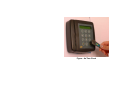
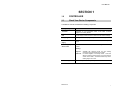
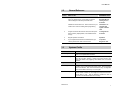
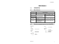
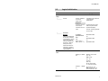
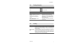
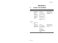
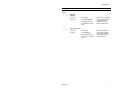
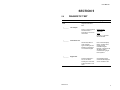
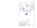
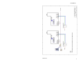
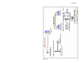
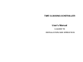
TIME CLOCKING CONTROLLER User's Manual A GUIDE TO INSTALLATION AND OPERATION Figure: An Time Clock Table of Contents 1.0 1.1 1.2 1.3 2.0 2.1 2.2 3.0 3.1 3.2 3.3 3.4 3.5 3.6 MICRO ID CONTROLLER ..............................................................................1 Check Your Device Components .................................................................1 General Reference.......................................................................................2 Systems Profile ............................................................................................2 TO START UP THE CONTROLLER...............................................................3 Wiring...........................................................................................................3 Cold Start & Master Card Registration.........................................................3 OPERATION ...................................................................................................4 Menu Selection ............................................................................................4 Functional programming tree chart of the MT45 ..........................................4 Logical Initialisation......................................................................................5 Clocking Information ....................................................................................6 Clocking .......................................................................................................6 Printing of Records ......................................................................................7 4.0 GENERAL PROGRAMMING ..........................................................................8 5.0 DIAGNOSTIC TEST......................................................................................10 User Manual SECTION 1 1.0 CONTROLLER 1.1 Check Your Device Components A standalone controller constitutes the following components. Primary Components Details controller Depending on your purchased model, it has either a built-in Wiegand or Proximity Reader. LCD For the display of date and time as well as access status message. 12-key Keypad The keys are used for programming and session clocking. Line to 12V Power Supply Power line is located at the back of the MT45 unit, to a 12V powersupply. Card or Key-shaped Access Card Access Cards for the MT45 unit comes in Wiegand or Proximity Format. Reading: Key form - Available with wiegand format only and reading requires touching the surface of the reader. Card form - For either Wiegand or Proximity format. Card form allows a maximum reading range of 2 inches from the surface of the reader. An external reader may have a reading range of 5 inches. Sounder relay Revision 2.0 The controller provides an output relay for sounder installation. 1 User Manual 1.2 General Reference Section WHAT TO DO REFERENCE TITLE Set up the unit with connections to a Sounder device and a 12V power-supply. Ensure that you have the relevant Wiegand or Proximity formatted cards. MT45 Controller Diagram (Wiring); Turning on the Controller Initialize the device before use. Select a card to be your master card in order to enable general programming. Initialization: To cold start and register a master card 4 Program the device with relevant Timer, Sounder (Time Zone, Duration), Display Mode, User-enabled session change. To Program The Controller 3 Regular operation commands Operation 5 If you suspect that the device has malfunctioned, you need to perform basic tests over the device. To perform Diagnostic Test 2 1.3 Systems Profile Functional Card storage Note that card storage is not available. The controller reads any valid card compatible with its Reader. Transaction storage Maximum transaction storage space is 1920 records (accounting for both 'IN' and 'OUT' clocking). Reads only 6-digit (20 bits) card. With 20-bit limited card, applying card number must not exceed '065536'. Physical Power surge The occurrence of power surge would cause the controller to self kick-start. Prior configurations will remain intact. Normal operation will not be affected. User is recommended to carry out diagnostic test to ensure data and memory is not corrupted. Clock accuracy Power surge does not affect the accuracy of the clock. Over the course of time, however, the clock might run-off by 30 seconds to 1 minute within a year. User is advised to update the clock in accordance to individual's demand on accuracy. Revision 2.0 2 User Manual SECTION 2 2.0 TO START UP THE CONTROLLER 2.1 Wiring Refer to appendices for wiring diagrams. No. Description Reference No. 1 Cabling: Connection to a PC, Sounder, and Power Supply CT45-501 2 Controller's wiring for reader CT45-101 3 Networked wiring to an RS485 convertor CT45-102 External READERS: Take note, that external readers are connectable at pins labelled CN5 or CN6. 2.2 Cold Start & Master Card Registration What to do first What you will see What to do next Press Key '1', turn off and on the power then release the Key. MT45……v<x.y.z>, where <x.y.x> is the version number Key in PIN: '123456' Card Type: Wieg To do selection of a Card Type: Key in Master: <Your selected card> Key 8 (UP '') Key 0 (Down '') Select your relevant card type: Wieg or Prox. It is 'Wieg' by default. Press 'Enter' to initialize the controller. ……Initialize…….. <hh:mm:ss> Revision 2.0 <date> 3 User Manual SECTION 3 3.0 OPERATION 3.1 Menu Selection To do selection of a function Keys Usage description For Programming For Regular Operation [If User-enable Mode is set ON]. To scroll through functional menu or sub-menu items. Keys between '0' and '9' (including '0' and '8') are for the selection of session. '8' (UP '') '0' (Down '') '#' (Enter) It is used for entering submenu level. For the selection of 'OUT' indicator. (ESC) It is to escape from a submenu level back to main menu or to escape from the programming mode. For the selection of 'IN' indicator. '*' 3.2 Functional programming tree chart of the MT45 Date & Time Timer Time Zone |________ Sounder Time Zone Controller Setup |________ |________ Sounder Duration Set Double Clock Comm setup |________ |________ Unit No Baud Rate Revision 2.0 Printing |________ Print Transaction Diagnostic Test |________ |________ |________ |________ |________ Test outputs Comm Echo Test Keypad Test Reader Test Memory test 4 User Manual 3.3 Logical Initialisation What to do What you get Unit No: <between 01 and 16> Controller's unit number for communication identification. Comm setup |________ Unit No Press 'Enter' Response |________ If entered unit no. is out of bound System will ignore value when user press 'Enter'. If entered unit no. is valid System will display: To select a particular baud rate Baud Rate: 9600 'Unit No', meaning returned to menu item. Baud Rate Briefing 9600 is the default rate for PC and controller's communication, as well as for daisy chaining among controllers in a single bus. (Refer to wiring CT45-102.) Use: Key 8 (UP '') Key 0 (Down '') Or Baud Rate: 4800 Or Baud Rate: 2400 Other baud rates are alternatives. Refer to your local dealer if you need assistance. Date & Time Ddmmyyw..<00000 00> dd: day of the month (01 - 31) mm: month (01 - 12) yy: year (00 - 99) w: day of the week (0 - 6 for Sun to Mon) Hhmmss….<00000 0> Revision 2.0 hh: hours (00 - 23) mm: minutes (00 - 59) ss: seconds (00 - 59) 5 User Manual 3.4 Clocking Information Configuration Sequence Step 1 Define Step 2 Define → Timer Sounder Time Zone Limitation notes Timer Sounder Time Zone There are 4 available Timer records (1, 2, 3 and 4). The turning on of sounder is based upon its applied time zone and sounding duration. Each Timer record constitutes 16 activation-times, for the purposes of Sounder. There is only 1 set of Time zone consisting of 7weekdays' timers. So, each weekday's timer would be either 1, 2, 3 or 4, which in turn relate to sets of activation-times. When configuring, the hours range is between 0001 and 2359. A Time Zone Å 7 Day's Timers Å Each Day's Activation-times 3.5 Clocking Subject Description on Operational Responses Clocking Just badge a valid card at the controller. Card will be registered with the displaying of card number and indicator '>> PASS <<'. The controller will not respond if invalid card format is attempted. It allows continuous swiping (or high traffic clocking). Double Clocking (DC) To avoid the registration of double clocking sequentially, user is advised to apply relevant DC card reject duration (with at the least 3 seconds) (e.i. via 'DC Time' - refer to programming section). The controller, however, would actually able to read the same card again within the same minute if there is intermediate distinct card number(s) being applied. Revision 2.0 6 User Manual 3.6 Printing of Records The printing of records in MT45 concern only recorded transactions. How it is done • Via a TM, TM32 or Hyper Terminal; or • Via software, called WinCom DigiTime (for transactions only). Refer to its manual. Subject Description Recorded Transactions System has been allocated with 1500 transactions space. Steps [MT45] -------------------- [PC] Ensure that the controller (at CN7) is connected to your PC's communication port via an RS232 cable. Your 'TM' is activated accordingly. At MT45, enter programming mode using your master card. Select 'Printing' and follow by 'Print Tran' menu. Output ** Micro-ID MT45 ** ** CLOCKING REPORT ** UNIT #: <controller's unit no for identification> MT45 V<version number> <dd/mm/yy> <hh:mm> <card number> SAMPLE ** Micro-ID MT45 ** ** CLOCKING REPORT ** UNIT # : 16 MT45V1.0.1 01/10/02 03:04 050607 04/10/02 09:46 030328 04/10/02 09:46 030450 08/10/02 15:33 030420 08/10/02 16:29 030420 Revision 2.0 7 User Manual SECTION 4 4.0 GENERAL PROGRAMMING What to do What you get Press 'Enter'. System exits back to Timer menu item upon the completion of each Timer setup. Timer (Applicable to Sounder Time Zone only. There are 4 available Timers. For each Timer, there are 16 available entries of activationtimes.) Key in Timer Set: <between 01 and 04> For the selected Timer set: At '1:', key in <between 0001 and 2359> Do the same, if relevant, for '2:', up to '16:'. Press 'Enter' to save the setup. Time Zone |________ Sounder Time Zone (There is only 1 sounder timezone that applies any of the defined Timers.) Press 'Enter'. Key in the TZ Set by: Key in for Sunday: <Timer between 01 and 04> System exits back to Sounder TZ menu item upon the completion of the setup. Press ' Enter' for subsequent day. Do the same, where relevant, for Monday to Saturday. Revision 2.0 8 User Manual What to do What you get Press 'Enter'. Sounder will be turned on for the specified duration whenever the clock matches with the set timer's activation time. Controller Setup |________ Sounder Duration (It is set in seconds) Key in Sounder ON: <between 00 and 99> Press 'Enter' to confirm setup. |________ Set Double Clock (It is set in seconds) Press 'Enter'. Key in DC Time: <between 00 and 99> Press 'Enter' to confirm setup. Revision 2.0 User will be prevented from clocking (badging card more than once) continuously within the specified duration. 9 User Manual SECTION 5 5.0 DIAGNOSTIC TEST What to do Press 'Enter' to get into diagnostic sub-menu / field. Diagnostic Test |________ Test Outputs Press '1' on the keypad to activate Sounder Press 'Esc' to exit or turn off the tests. |________ Type something at PC's keyboard or press keys on controller's keypad. Action Pressed '1' ∏ Sounder will be activated. PC's screen will display letters / numbers when pressing keys at controller's keypad. Likewise, controller's LCD will display letters / numbers when typing at PC's keyboard. Keypad Test Press keys between '1' and '9', and 'Enter'. Pressing 'Esc' will cause system exit back to submenu. Revision 2.0 Default Display 1:Sounder Comm Echo Test Activate TM, TM32 or Hyper Terminal |________ What you get Corresponding keyed number will be displayed on the controller's LCD. 10 User Manual What to do |________ What you get Press 'Enter' to get into diagnostic sub-menu / field. Diagnostic Test Reader Test Wave / Badge card at controller / Reader. Corresponding Reader's and Card's information will be displayed on the controller's LCD: C: <Card no.> P: <PIN no.> At TM or Hyper Terminal screen: C: <XXXXXX> P: <xxxx> C: <YYYYYY> P: <yyyy> |________ Memory Test 'Press # to Start' will be displayed. Press 'Enter'. If there is no problem with the controller's memory, '……GOOD……' will be displayed; otherwise '……BAD…….". Under very rare circumstances, if 'Bad' reading is obtained: Conduct a cold start to the controller and repeat the memory test. If problem persists, refer to your local dealer for assistance. Most likely the controller requires repair. Revision 2.0 11 User Manual Revision 2.0 12 User Manual Revision 2.0 13 User Manual Revision 2.0 14