1
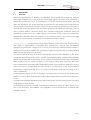
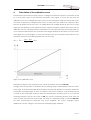
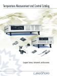
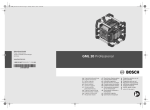
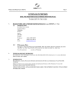
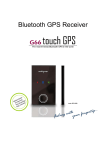
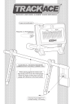
UltraLab ULS User Manual 2007 GENERAL ACOUSTICS UltraLab ULS User Manual User’s notes: Page 2 UltraLab ULS User Manual Table of Contents 1. GENERAL...................................................................................................................................................4 1.2 WARRANTY STATEMENT..................................................................................................................................6 2.3 THE PRINCIPLES OF MEASURING DISTANCES BY MEANS OF (AIR) ULTRASOUND....................................................... 8 2.3.1 COMPENSATION WITH AN INTEGRATED TEMPERATURE PROBE (STANDARD FOR USS)........................................10 2.3.2 COMPENSATION WITH AN EXTERNAL TEMPERATURE PROBE............................................................................ 10 2.3.3 COMPENSATION USING A REFERENCE MEASUREMENT..................................................................................... 10 3. OPERATING THE SYSTEM. BENCHTOP INSTRUMENT ULS40-D........................................... 11 4. CALCULATION OF THE CALIBRATION CURVE......................................................................... 12 4. CE CONFORMITY STATEMENT....................................................................................................... 14 5. TECHNICAL SPECIFICATIONS......................................................................................................... 14 Page 3 UltraLab ULS User Manual 1. General 1.1 Safety instructions For your own safety and for the safe operation of the system, please read the following instructions carefully PRIOR to operating the system for the first time. The ULTRALAB® ULS laboratory instrument, as well as the associated ultrasound sensors, represent state-of-the-art technology and comply with the latest safety regulations. The manufacturer has made every effort to guarantee safe operation. The user must ensure that the instrument is set up and installed in such a way that its safe usage is not impaired. The instruments are factory tested and were delivered in a safe operational condition. This User Manual contains information and warnings, which must be observed by the user under all circumstances to ensure safe operation of the instruments. • The instrument may only be put into operation by authorised persons and only operated by trained personnel. All users working with this instrument must read the User Manual prior to any operation. • The user may only perform the repair and maintenance work described. Only the specified parts are to be used. Servicing work may only be carried out by authorised service technicians from GENERAL ACOUSTICS. • All instruments and additional devices used for this purpose must be properly earthed. • The earth leads must not be interrupted at any point. • The ULTRALAB® ULS laboratory instrument may only be operated within the specified temperature range of -20 to +70°C. Otherwise measurement inaccuracies and instrument faults or defects may occur. The temperature stability of connection cables must match the operating temperature of the measurement system. • The sensor should only be connected to the instrument when it is switched off. • The sensors are to be treated with care and are only to be screwed in hand-tight; otherwise there is the risk of damage. Sufficient leverage is obtained from the sensor casing itself. • Avoid electrostatic discharges. • The ULTRALAB ® ULS laboratory instrument must not come into contact with liquids. • Never operate the instrument at sites where water may get into the instrument. • Also take care that the instrument is always operated above the water line of experimental reservoirs. Protect the instrument against falling into water. • Isolate all system devices from the mains before undertaking cleaning. Ensure there is no current. Do not use aggressive cleaning chemicals, liquid cleaners or sprays; only use a damp cloth. Never bring this or any other cloth into contact with parts of the system that will subsequently conduct electricity. Page 4 UltraLab ULS User Manual • Never attempt to open instruments with objects or to insert objects into an instrument. The voltages existing in the instruments can lead to short-circuits and electric shocks. • Ensure adequate ventilation when operating the ULTRALAB® ULS. As the instrument has low power consumption, it requires no additional ventilation under normal conditions. However, the instrument should never be placed on a source of heat (computer monitors, radiators …). Only operate the ULTRALAB® ULS at the intended mains voltage of 230 VAC (optionally 110 VAC). • For safety reasons, the ULTRALAB® ULS is provided with a sealed appliance plug with earth contact for its mains power. In this context, only appliance cables and plugs with earth contacts may be used. Operation of the system is prohibited if you do not have this option. Never use an extension cable without an earth contact. • The instrument is protected from mains voltage by a blowout fuse in the appliance plug. A finewire fast-blow fuse (G fuse 5 x 20 mm) compliant with IEC with a nominal value of 0.25 A is to be used as a replacement. Only the specified values may be used. Higher tripping values or bridging of fuses is not permissible. If the fuse repeatedly blows, the Service Department of GENERAL ACOUSTICS should be informed, as the cause would need to be resolved. • We recommend protecting the circuit with FI protective switches to ensure safe operation of your complete system. • Take care that power cables are not worn, abraded or otherwise defective. When routing connecting cables, make certain that the cables do not represent an obstacle or risk of tripping. • When using extension cables, the total nominal current of all the devices connected must not exceed the allowable maximum current of the cable. The current ratings of all devices connected to a single plug should never exceed 15 A, unless the plug is specifically designed for this purpose. If you are unsure what type of mains power exists in your premises, ask your Safety Officer or an authorised electrician. It is imperative to isolate instruments from the mains in the following cases: • If power cables or plugs are worn or damaged. • If water or any other liquid has found its way into one of the instruments. • If the instrument is not working correctly despite following the specified operating instructions. • If one of the instruments has fallen down or the chassis is damaged. • If the instrument shows any noticeable departure from normal operation. • If the sensor connections have become wet. With the exception of the actions explicitly specified in the manual, you should never attempt your own repairs on devices belonging to the ULTRALAB® ULS system. Besides the resulting revocation of warranty coverage, you also risk an electric shock or other injury from the components. All maintenance work, unless explicitly described in the manual, should only be carried out by GENERAL ACOUSTICS. Page 5 UltraLab ULS User Manual 1.2 (1) Warranty statement Warranty period GENERAL ACOUSTICS GmbH, as manufacturer, will, itself or through its authorised sales partners, provide end-users with warranty coverage on all GENERAL ACOUSTICS products purchased as new and unused for a period of 12 months from the date of sale. (2) GENERAL ACOUSTICS procedure Any part, which has been correctly used and is found to be defective as a result of manufacturing and/or material faults within the above-mentioned warranty period, will either be repaired or replaced with a new part by GENERAL ACOUSTICS after expert opinion has been sought. Material and/or labour costs arising as a result will not be charged. All exchanged parts become the property of GENERAL ACOUSTICS (3) Conditions for labour rendered under warranty Instruments delivered must have been operated correctly, unauthorised modifications or repairs must not have taken place and the benchtop instrument must not have been opened. (4) No warranty claim exists in the following cases - Parts subject to normal wear - Damage caused by incorrect maintenance, fitting and addition of non-approved parts and devices, as well as unauthorised modification of components - Damage caused by electrolysis - Damage caused by fire or accident, incorrect usage, misuse or negligence - Damage/rust/corrosion caused by the entry of water (5) Explicit or tacit guarantees These guarantees confer special rights to you, and you may also have other rights, which differ from country to country or from province to province. Where these guarantee claims apply, all other explicit or tacit guarantees provided by GENERAL ACOUSTICS automatically lose their validity, incl. all market access guarantees or guarantees of fitness for every specific purpose. Conversely, the guarantees thus arising are limited to the period of this warranty. Neither sales partners nor traders are authorised to make any other assurances, representation of facts or warranty offers than those contained in the warranty conditions. Page 6 UltraLab ULS User Manual 2. Introduction 2.1 Overview Ultrasound measurement of distances in laboratory measurement technology has become increasingly established in recent years. The advantages gained are quite clear: particularly in small-scale experimental set-ups, it is imperative to avoid any mechanical intervention that may affect the experiment, but at the same time, parameters must be measured and evaluated. This not only applies to laboratory operation and the medium of water. As the distance to an object is measured by sound propagation time measurement, and not by intensity measurement, as is the case in optical methods, ultrasound sensors have excellent background suppression. Almost all materials that reflect sound are reliably detected, irrespective of their colour. Even transparent materials and thin foils present no problems for our ultrasound sensors. As a result of their high sensitivity, our sensors are also predestined for the detection of liquid surfaces. GENERAL ACOUSTICS USS ultrasound sensors permit distance measurement from 30 mm to 3.4 m and, thanks to high-resolution propagation time measurement, measure with sub-millimetre resolution. The sensors with a range up to 1.3 m can even resolve the measured distance down to an impressive 0.18 mm. In addition, the unit features a high measurement rate up to 75Hz, allowing highly dynamic processes to be recorded. The sensors measure in dusty air as well as through fine fog. Even thin deposition on the sensor membrane does not impair the sensor’s function. These characteristics, combined with extremely slender sound cones (with no secondary cones), make for completely new laboratory applications. The ULS series of ULTRALAB® sensors are based on an ultrasound pulse echo technique. They have been developed for temporally and spatially high-resolution measurement of distances in air. The easy-to-use ULTRALAB® ULS laboratory instrument excels as a consequence of the diverse functions implemented, making it suitable for use in complex measurement tasks without having to set a series of parameters. The measurement object can be, for example, the water surface as a level or the moving water surface as a wave. This is where the temporally highly resolved distance measurement comes into its own. A complex measurement algorithm ensures high measurement accuracy and resolution, as well as a high degree of data security. The analogue measurement voltage, proportional to distance, is output at a BNC socket on the front of the instrument. This facilitates easy integration of the ULS system into an existing data acquisition system. Page 7 UltraLab ULS User Manual 2.2 System components The ULTRALAB® ULS instrument system consists of the following components: - Laboratory apparatus ULTRALAB® ULS - At least one ultrasound sensor of type USS XXX (XXX specifies the measurement ranges in mm), and the - Sensor cables between the sensor and instrument (10m is standard). Example: USS20130 is an ultrasound sensor with a measuring range of 200 to 1300mm, i.e. it has a blind zone below 200 mm from the sensor’s lower edge and a maximum measurement range of 1300 mm from the sensor’s lower edge. That is a net range of 1100 mm or 1.1 m. The selection of a suitable ultrasound sensor depends on the nature of the surface to be measured, the maximum measured distance and the required measurement resolution. The following models are currently available: Sensor identifier Measurement frequency [kHz] USS325 320 USS635 USS20130 USS35340 Response time at Technical analogue output resolution [mm] [ms] 40 0.18 400 55 200 70 120 130 Update rate Reproducibility1 ± 1.00 75 Hz 0.18 ± 1.00 75 Hz 0.18 ± 2.00 50 Hz 1.00 ± 3.0 20 Hz 2.3 The principles of measuring distances by means of (air) ultrasound The ULTRALAB® ULS sends out an acoustic pulse via the ultrasound sensor. The ultrasound pulse emitted is reflected on the measurement object and is received back as an echo. A key aspect when it comes to measuring distances is the time required for the transmitted pulse to cover the distance to the respective measurement object and back. This sound propagation time is measured by the ULTRALAB® ULS with high resolution. The measured propagation times are averaged. A tolerance band (expectation range) is set around the average propagation time. Only measurement values that lie within the expectation range are admitted for further calculation of the measurement value. The average value is modified according to changes in distance. The measured distance is converted to a voltage signal (0-10V) proportional to the distance. A US sensor can be divided into three functional groups for purposes of illustration: 1. The ultrasound converter 2. The evaluation unit 3. The output (end) stage The sound source (piezo crystal) is stimulated to oscillate for a brief period. This emits ultrasound waves. 1 Reproducability, or more precisely: accuracy. This implies the accuracy, which remains constant under variable conditions Page 8 UltraLab ULS User Manual 1. ultrasound converter 2. evaluation unit 3. output stage target object transmitted pulse echo pulse transmitted pulse amplitude time reception readiness repetition time transmitted pulse input echo pulse output Figure 1: The functionality of an ultrasound-based distance sensor The sound source is then switched to receive (comparable with a microphone) and the incident US pulses are evaluated. The propagation time of the sound to a possible target is determined within the defined measurement window. A voltage value is output, proportional to the measured distance. The sound propagation time and the measured distance obtained from it will depend to a certain extent on the following environmental conditions: Air temperature: The sound propagation time is dependent on air temperature (0.17%/K). Relative to an air temperature of 20°C, the speed of sound changes by +3.5% at temperatures of approx. 40°C and the measured distance in turn by around 3.5%. These temperature-related changes can lead to a shift in the localisation of the water surface. Humidity: The speed of sound increases by a maximum of 2% between dry air and air saturated with moisture. Consequently, the switching distance changes by a maximum of 2%. Air pressure: Taking into account all normal atmospheric fluctuations (± 5%), the speed of sound fluctuates by around 0.6% at a fixed location. The resultant shift in echo propagation time may be considered negligible. Air currents: Changes in the speed of sound arising from the continuous changes in current direction, through changes in air current velocity, as well as the resulting turbulences, is very difficult to formulate in a general statement. Normally these turbulences can be ignored. For wind speeds Page 9 UltraLab ULS User Manual above 50 km/h, changes in the speed and direction of the sound of more than 3% cannot be ruled out. General guide: Under normal environmental conditions, changes in the speed of sound are not of any notable significance. The distance in metres is measured from the propagation time taking into account the speed of sound. Compensation should be performed if the speed of sound varies significantly. 2.3.1 Compensation with an integrated temperature probe (standard for USS) This type of compensation guarantees accurate results for slight variations in environmental conditions (laboratory). More extensive compensation methods must be applied if conditions are subject to considerable changes along the measurement path. For this purpose, the integrated temperature compensation of the sensors must be deactivated by the manufacturer. 2.3.2 Compensation with an external temperature probe Here temperatures along the measurement path are measured and used for correction. As a consequence of temperature variations along the measurement path, measurement inaccuracies can still arise, which are not straightforward to measure. The direct measurement of temperature can permit very accurate measurement of the speed of sound. The correction of the speed of sound in air and the associated correction of distance values is, however, only possible offline, i.e. after a measurement. 2.3.3 Compensation using a reference measurement The most accurate type of compensation is that of a reference measurement. This can be necessary for very long measurement paths (several metres) or for extremely variable conditions. In the case of density variation or stratification of air masses, through which the ultrasound pulse must penetrate, it is necessary to measure the real speed of sound. An ULTRALAB® ULS measurement channel can be specially used for such applications as a reference path. The reference sensor emits sound along a path of maximum possible length, parallel to the measurement channel, through the same medium/media as the measurement path itself, onto a fixed target at a defined distance (e.g. 1.0 m when using the USS20130 sensor). The same influences on the speed of sound are necessarily measured as those on the measuring path itself. If the reference channel is also recorded, variations in the distance to a fixed object can be concluded from the data from the change in the speed of sound, and consequently used for highly accurate compensation. Page 10 UltraLab ULS User Manual 3. Operating the system. Benchtop instrument ULS40-D The benchtop instrument has 4 independent channels for easy operation of up to 4 USS series ultrasound sensors. Each channel can be switched individually; the LED shows the operational status of the channel (green=on, red=off). The sensor cable is connected to the BNC socket; the output signal on the BNC socket OUT (0-10V). Page 11 UltraLab ULS User Manual 4. Calculation of the calibration curve The ultrasound measurement system outputs a voltage proportional to distance of between 0 and 10 V at the BNC output of the benchtop instrument. From Figure 2, it may be seen that the calibration curve is a) a straight line and b) does not pass through the origin. This means that a) the conversion of distance to voltage is linear and b) an offset has to be added to the distance value because all ultrasound sensors have a so-called blind zone starting directly at the sensor’s lower edge (see specifications of the individual sensors). Using an example, it will be shown here how the calibration curve is calculated with the parameters. It is recommended that the experimental setup be measured beforehand, the expected wave heights determined and then to set the sensors accordingly. If e.g. wave heights of 10 mm are expected, the sensor should be placed close to the expacted waves but considering the blind zone of the sensor. hmess = U mess × hmax − hmin + hmin U max − U min Figure 2: The calibration curve Example from Figure 3: The expected wave or level fluctuations are around 600 mm. The right sensor for this task is a USS20130 with a measuring range of 200-1300mm below the sensor lower edge. As environmental disturbances always increase with distance, it should be attempted to bring the measuring range as close as possible to the sensor. Therefore, a measurement set-up as shown in the lower figure would be ideal. The window limits are shifted (see 3.2.1) so that the measuring window near the sensor lies at 200 mm and the measuring window away from the sensor at 1000 mm below the sensor edge. This results in a measuring range of 1000-200=800 mm, the value representing the expected max. wave amplitude. The sensor’s analogue output distributes the output voltage of 10V across the measuring range of 800mm: Page 12 UltraLab ULS User Manual Figure 3: Measuring setup Page 13 UltraLab ULS User Manual 4. CE conformity statement THE INSTRUMENT CONFORMS TO THE REQUIREMENTS OF THE EEC DIRECTIVE 89/336/EWG AND THE REVISIONS THROUGH 92/31/EWG AND 93/68/EWG ARTICLE 5 PERTAINING TO “ELECTROMAGNETIC COMPATIBILITY”, AS WELL AS 73/23/EWG AND THE REVISIONS THROUGH 93/68/EWG ARTICLE 13 PERTAINING TO “SAFETY”. 5. Technical specifications Instrument model Sensors Measuring range Accuracy ULTRALAB® ULS-40D USSxx, IP 65, M30x1.5, with temperature compensation, nickel plated brass tube (optionally stainless steel) between the blind zone (from 30 mm to 350 mm) and the detection range limit (from 250 mm to 3400 mm) up to +/- 1mm (under stable environmental conditions) (dependent on sensor model) Resolution from 0.18 mm to 1 mm (dependent on sensor model) Measurement from 20 Hz to 75 Hz (dependent on sensor model) frequency Voltage output BNC socket: 0–10 V Power supply 230 VAC, 250 mA (110 VAC optional) Chassis approx. 250 / 90 / 190 mm width / height / depth IP 50 Temperature -20…+70°C range Delivery package laboratory instrument ULS-40D, ultrasound sensor USSxx, 10 m sensor cable, user manual, mains cable Page 14