1
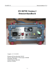
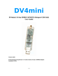
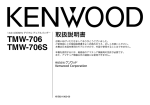
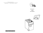
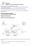
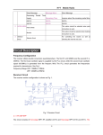
DV 3.0 User ManualV1.0 DV 3.0 User Manual Edition:11.05.2013 for FW Version: DV 1.37 and GW 1.23 Planning and Network Technology:DG1HT Software:DJ0ABR Distribution, Software:DH2YBE Hardware Development and Manufacturing:DG8FAC Documentation and Pictures: DH5RAE Translation: N1DL -1- DV 3.0 User ManualV1.0 Table of Contents: Technical Data: ............................................................................................................. 3 Connections: ................................................................................................................. 5 Power Supply: ........................................................................................................5 USB Connector: .....................................................................................................5 Ethernet Connector: ...............................................................................................6 Transceiver Connector: ...........................................................................................6 Pinout DVRPTR-V3: .......................................................................................6 Microphone Connector: ...........................................................................................7 External Speaker (LS): .............................................................................................8 Internal Speaker: ....................................................................................................8 User Controls: .............................................................................................................. 8 TFT-Display: .........................................................................................................8 Rotary Switch: ........................................................................................................9 Basic Functions: ............................................................................................................ 9 Callsign Editing: ........................................................................................................... 14 Connection to a PC: ..................................................................................................... 15 Operation in the Car: .................................................................................................... 16 Stand-Alone(withoutPC)Repeater: ................................................................................... 16 Stand-Alone(ohnePC) mit Netzwerk: ............................................................................... 16 Stand-Alone REPEATER (withoutPC) with Internet: .......................................................... 17 Operation with PC Control Center: ................................................................................. 17 Firmware Update: ......................................................................................................... 19 Firmware Update DV-Controller: ............................................................................ 19 Manual Start of the Bootloader: ...................................................................... 20 Firmware Update Gateway-Controller: ..................................................................... 20 -2- DV 3.0 User ManualV1.0 Technical Data: The DV-3.0 board is a high quality 4 layer board with generous ground and power planes and thus extremely interference free. It serves as the motherboard for the plug in Ethernet board, the AMBE board, the Display as well as the iTRX board. The modular concept allows future expansion and improvements. In addition one can create new modes by just changing a module board. The development of the iTRX is continuing and will also fit a V2 board. A mini SD card slot on the motherboard provides extra storage capacity. This may in the future enable storage of repeater and/or map information that can be accessed if needed. It is made for these digital voice modes: Stand-Alone (no PC and Internet): DV-Transceiver without PC(e.g. mobile operation in the car) Repeater with Gateway connection With or without a PCbut with an existing Internet connection: DV-Transceiver with PC Hotspot -3- DV 3.0 User ManualV1.0 Repeater GatewayLink DongleMode (talk directly to the internet) Conference Mode Standard Mode (without PC):; If no PC is connected then after “Power On” of the DV 3.0 all modes can be selected. As is the case with the DVRPTR V2 board the connection works via the Ethernet port. This also allows to completely control the DV 3.0 remotely without a PC at the repeater site (like on a mountain top) with the Control Center running in the shack of the repeater administrator. This simplifies the maintenance of the repeater and saves travel time and expenses. In addition there is still a USB connector on the board. Power supply: 12 V Current consumption: about 100 mA Ethernet: IP via DHCP Speakers: 2 speakers front/internal can be connected Microphone: any microphones can be connected via patch panel 9-Pin SUB-D:connector for GPS mouse, automatic insertion into DV data stream, Power connection and an additional serial interface as well as all the signals that are on the TRX socket. Transceiver: external mobile TRX or optional internal iTRX Display Interface: for the 160 x 128 TFT-screen. All indicators will be displayed here. User Switch: rotary/push switch (knob) -4- DV 3.0 User ManualV1.0 Connections: Power Supply: 2,5mm DC-Plug center pin:+12Volts(10 to 14Volts) ring pin: GND A low-noise power supply should be used. When operating in the car the 12V line should be buffered with a capacitor of at least 10,000 uF/25V. (otherwise the board may commence a reset when starting the car) USB Connector: Mini-B-USB Connector used to connect to a PC. Under Windows the xDVRPTR-32-64-2-inf driver must be installed. This driver can be found in the Yahoo group DVRPTR. This driver generates a virtual COM port which is automatically detected by the Control Center Software. Under Linux no drivers are needed. The port will be found automatically. It may be necessary to start the Control Center with root privileges. However the recommended method is to use an Ethernet connection. (however not both at the same time!) -5- DV 3.0 User ManualV1.0 Ethernet Connector: 8-pole Western plug (RJ45), any standard network cable can be used. Use this to connect the board to a PC or to the Internet if in stand alone mode. If the Control Center is in the same local network, the IP address is automatically found. With an external network the IP address must be entered manually. It is also possible to use a dyndns address and port forwarding so that multiple DV 3.0 boards can be addressed at the same location. Transceiver Connector: Pin out DVRPTR-V3: 6-pinMiniDIN Plug: it is compatible with the 9k6 jacks of standard transceivers. Therefore a standard PS-2 cable can be used for the connection. This picture shows the Mini-DIN socket mounted on the 3.0 board looking at the socket. ICOM, Kenwood, Yaesu and other transceivers have this pin allocation: -6- DV 3.0 User ManualV1.0 Funktion Pin TRX 9k6 input of the TRX to be connected to the TX-Audio output of the DVRPTR 1 GND 2 PTT 3 Output (9k6) of the TRX to be connected to the RX-Audio input of the DVRPTR 4 AUX-socket: Used to connect a GPS mouse. Recommended is one with the SIRF-3 chip set. It must have a serial interface and be PC compatible (not TTL). Furthermore this socket also provides access to the power supply, the pins of the TRX connector and an additional serial interface. As a SUB-D socket is easier to solder and the plug can be secured with screws, it is preferred for repeater and mobile use. Pin configuration: Pin 1: Pin 2: Pin 3: Pin 4: Pin 5: Pin 6: Pin 7: Pin 8: Pin 9: 12V IN TxD (AT)(GPS) RxD (AT)(GPS) TxD (Ti) GND RxD (Ti) PTT ( (parallel to Mini DIN6) RxAF (parallel to Mini DIN6) TxAF (parallel to Mini DIN6) (AT) (the serial connection of ATMEGA) (Ti) (the serial connection of ETH module) Microphone Connector: 8-pole Western plug (RJ45), now common with most microphones. With the 8-pole patch panel (behind the microphone jack) almost any microphone can be adapted. -7- DV 3.0 User ManualV1.0 The assignment is compatible with Yaesu microphones. If you use Yaesu you can connect the patch panel 1:1. For other microphones, the patch panel must be connected as required.. Pin assignment: 1 2 3 4 5 6 7 8 ... do not connect, for future expansions ... GND PTT ... PTT ... AUDIO ... GND AUDIO ... +5 V ... do not connect, for future expansions ... do not connect, for future expansions If a dynamic microphone is used, (e.g. MD100 or similar) DO NOT connect the +5V line (this connection would couple noise into the mic line). External Speaker (LS): 3.5mm mono jack for the connection of an external speaker with 4 or 8 ohms, or a headset. Internal Speaker: 2.56mm 3-pin connector for the connection of a speaker with 4 or 8 ohm mounted inside the chassis. Each of the outer pins can be connected to the speaker, the middle pin is not used. The speaker must NOT have any ground connection!(One needs a larger box for that installation) User Controls: TFT-Display: 160 x 128 Pixel -8- DV 3.0 User ManualV1.0 262 000 colors size 40 x 30 mm 1.8 inch diagonal Rotary Switch: Selection of menus and adjusting operating values. The current settings are displayed on the TFT display and also shown as a color on the rotary switch (knob). Basic Functions: The following functions can be selected by pressing the knob. Then the value can be changed by turning the knob. An additional pressing selects that menu item (menu line turns red) and one can change the value by rotating the knob. Pressing the knob once more brings you back to the menu. If you press the knob ca. 2 seconds it will end the menu operation. The following menu items are currently available: iTRX frequency small * iTRX frequency wide * Band Selection Duplex Offset * Operating Mode iTRX Power * DCS Server DCS Channel CCS on/off Language Display style Repeater call Mycall Urcall Items marked * can only be selected if an iTRX board is inserted. Speaker – Volume: Knob Color: White Display: LS - the lower line shows the value While in receive mode this adjusts the speaker volume -9- DV 3.0 User ManualV1.0 Microphone – Volume: Knob Color: White (if PTT is activated) Display: MIC - the upper line varies with the adjustment While in transmit mode the Microphone amplification can be adjusted. If one presses the knob during transmit the AGC can be turned on or off. Display Style: Knob Color: yellow Allows to select smaller or larger fonts which may be easier to read in mobile operation. -10- DV 3.0 User ManualV1.0 Band Selection: Knob Color: RED Display: Band: 10m, 2m, 70cm, 23cm The band selection automatically adjusts the repeater module letter. It is not possible to enter this letter manually. 10m = E 2m = C 70cm = B 23cm = A If an iTRX is used then this setting selects the TRX band. The modules A and E are not selectable. iTRX frequency small: (only of the optional iTRX sub board is installed) Knob Color: RED Display: QRG 6.25 kHz (with 2m) or 12.5 kHz (with 70cm) In MENU press the knob and turn it until the menu position is reached, then press the knob and the font color turns red. By turning the knob the receive frequency of the iTRX can now be tuned in small steps. When the required frequency has been reached press the knob for 2 seconds. iTRX Frequency wide: (only if the optional iTRX sub board is installed) Knob Color: RED Display: QRG 100 kHz (with 2m) or 200 kHz (with 70cm) As above the Receive Frequency of the iTRX is adjusted with coarse frequency steps. Duplex Offset: (only if the iTRX option is installed) -11- DV 3.0 User ManualV1.0 Knob Color: YELLOW Display: DUPLEX OFFSET The offset frequency for working repeaters is selected here. In North America commonly 0.6 for 2m and 5.0 for 70cm. Operating Mode: Knob Color: CYAN (green-blue) Display: possible modes: DVTRX or Standalone Repeater Display Mode: Private Hotspot Public Hotspot Gateway Link Repeater DV-TRX + AMBE AMBE + Internet TRX + AMBE + Internet This allows the selection of the operating mode without a PC. Refer also to the chapter on mobile operation and standalone repeater. If a PC is connected and the PC software active then the actual PC selected operating mode is displayed and cannot be changed with the knob. If a PC is connected and the PC software is running, then the current mode is displayed and cannot be changed with the knob. TX-invers: (Only visible without an iTRX) Knob Color: VIOLETT Display: Txinverse: normal or reverse This is to set the TX polarity. Monitor the TX signal with an ICOM transceiver then set the Txinvers mode. If receiving with a DV 3.0 this setting is not required because it can receive both polarities. TX output level: -12- DV 3.0 User ManualV1.0 Knob Color: GREEN Display: Txlevel: AF voltage in volts adjust the level of the output signal during transmission. Usual values: Yaesu mobile transceivers: 0.7 V Kenwood Mobile Transceiver: 1.5 V To adjust this level listen to the transmitted signal with a FM Transceiver and compare the signal to another DV transceiver (e.g. ICOM). If in doubt use lower values as overmodulation leads to signal errors. However too low levels increase the error rate rapidly also. TX-Delay: Knob Color: GREEN Display: TX DELAY 100msec to 850msec After the PTT has been activated this adjustment allows the delay time after PTT is pressed. Common transceivers need about 300 msec. If you should use a slow radio you can increase this delay. iTRX output power: (only if iTRX option installed) Knob Color: BLUE Display: TXpower: high / low DCS-Server: Knob Color: YELLOW Display: Refl.: DCS001 To select a DCS reflector. This setting is only visible in the Stand Alone mode without PC (when a PC is connected than the PC software will handle DCS connections). DCS-Channel: -13- DV 3.0 User ManualV1.0 Knob Color: CYAN Display: Module: Y For selecting the DCS reflector channel (module). This setting is only visible in the Stand Alone mode without PC (when a PC is connected than the PC software will handle DCS connections). CCS-Mode: on or off Knob Color: VIOLETT Display: disconnected or Active To allow or reject CCS calls. (Callsign Routing). To manually cancel a CCS connection switch to „disconnected“ and back to „Active“. This setting is only visible in the Stand Alone mode without PC (when a PC is connected than the PC software will handle CCS connections). You can also use DTMF “A” to disconnect a CCS connection however. Language for Speech Announcements: Knob Color: BLUE Display: the selected language This language is used for announcements i.e. when connected to a DCS reflector Callsign Editing: The menu to enter call signs is slightly different as one has to make several entries sequentially. Press the knob and the text turns red with an underline showing the position. To edit a character first select it by turning the knob. The selected character is underlined. Then press the knob. The character will be highlighted inverse and by turning the knob you can select the number of letter. Then press the button again to store the new character value. This must be repeated until all positions are done. Now press the knob 3 to 4 seconds which will exit the menu. Required are: Repeater call MYCALL URCALL Of course these entries can also be made via the Control Center (in the DV-TRX window) However for mobile operation without a PC this menu will be needed. -14- DV 3.0 User ManualV1.0 Connection to a PC: Even if the DV 3.0 can work without a PC some operating modes require a PC to be connected. This can be done via USB or Ethernet. When operating via the Ethernet the DV 3.0 requests an IP address via DHCP. You must have a DHCP server in your local network (i.e. In the DSL router). This picture shows the automatic detection enabled. Whether USB or Ethernet, the control center detects the DV 3.0 automaticaly and requires no operator actions. (On Windows, of course, the USB driver must have been installed). A special feature is the operation via Internet at a distant location. For that this location does not require an official URL (web address). One can get a dynamic one for private use for example from www.dyndns.org. -15- DV 3.0 User ManualV1.0 In the Control Center one selects this URL in the Modem window and a connection to the DV 3.0 will be made. Important: The connection from the PC to the DV 3.0 is activated via TCP Port 23. If a Firewall is used then this port must be forwarded. The Control Center allows the selection of a different port. This allows to use several DV 3.0 boards or DVRPTR-2 boards to be controlled by assigning them to different ports. When operating with the Internet the Port 23 on the router at the DV 3.0 location must also be forwarded. Operation in the Car: When operating in the car voltage drops (especially when you start the car) can reset the DV 3.0 Therefore the 12V supply should be buffered with a larger electrolytic capacitor, at least 10,000 uF / 25V. With a 6-pin PS-2 cable the DV 3.0 can be connected to the packet radio jack of the mobile transceiver. Set the TRX to 9k6 mode. With the frequency and offset adjusted properly you can now operate in DV mode. Stand-Alone (without PC) Repeater: This mode allows to build a DV repeater very easily. It needs no PC or Internet, only the power supply for the DVRPTR and the transceiver. The setup is simple: the two transceiver (a transmitter and the other as a receiver) can be connected to the DV 3.0. Then the DV 3.0 immediately operates as DV repeater. This mode is especially useful in exposed locations where no Internet is available, or where no PC can be installed. The Internet connection is performed by a ground station using a second DVRPTR V1 or V2 or DV 3.0 board. This station runs in Gateway-Link Mode and sends the data via a normal TRX to the stand-alone repeater. (refer to Control Center “Gateway-Link mode). Stand-Alone (without PC) with Network: The DDV 3.0 board can work without any PC in all operating modes: Dongle, Hotspot, -16- DV 3.0 User ManualV1.0 Link, Repeater and all AMBE modes as DV-Transceiver and the Conference Mode. It's very simple to enter the PC-less standalone mode: Power ON, ready. As long as no PC software is running the DV 3.0 handles the internet traffic automatically and connects to DCS and CCS servers by itself. The bottom line of the display shows : „Standalone Mode“. As soon as a PC software is started (i.e. the ControlCenter) and connected to the board all internal network functions are deactivated and the control is given to the PC software. The display's bottom line shows: „PC connected“. : These functions are provided by the standalone mode: 1) Connection to DCS Reflectors (selectable by rotary knob) 2) Connection to CCS to handle Callsign Routing 3) Control of DCS and CCS with the commonly used DTMF codes. 4) Control of DCS and CCS with the commonly used URCALL entries. (Refer to the DCS list in the Control Center where all control codes are depicted. Stand-Alone REPEATER (without PC) with Internet: To build a complete DV repeater without a PC you need these components: 1. DV 3.0 board 2. RX and TX transceivers 3. Duplexer and antenna 4. Power supply 5. Network connection (Ethernet or WLAN via adapter) to the Internet Operation with PC Control Center: Selection of the Speaker: The external, internal or both speakers can be turned on or off in this menu item. -17- DV 3.0 User ManualV1.0 The most important selections: Dongle mode for own personal call sign: If selected all operating modes (especially Dongle or Hotspot/Simplexlink) will only be accepted if they are originating from ones own call sign. This prevents that other hams can utilize a private hotspot. Use old XREF and REF Linking: If selected the system will accept DTMF tones and thus can be remotely control the connection to Reflectors or make CCS calls. Announcements: If selected voice announcements will be made e.g. connected to reflector, or time announcements. Ref changing via HF: If selected the system can be remotely connected to reflectors. To do this the link request is entered into the URCALL on the radio. How this link request must be formatted is visible in every room in the DCS window. Remember to connect use the L in the 8th position, to disconnect use the U in the 8th position. e.g. DCS006NL Roger Beep: The system knows two totally different Roger Beeps. Both can be turned on or off here. Roger Beep that is transmitted via HF. In operating modes Hotspot, Link and Repeater (and Conference) at Beep will be sent at the end of the transmission to the radio. This data also includes further information which will be displayed as message text in the display of the radio. In operating modes where the local microphone and speaker are used (DV-TRX, Dongle) a Roger Beep will be created in the speaker when the other station stops transmitting. Pitch, Volume and duration of these Beeps can be adjusted. -18- DV 3.0 User ManualV1.0 Firmware Update: The DV 3.0 board contains two microcontrollers: Controller-1: this controller handles all Digital-Voice functions like repeater, hotspot, microphone, speaker ... Controller-2: this controller handles all network related functions like PC connection, DCS reflector connections ... New firmware updates are available for both controllers on a regular basis. The following description shops how to update these two controllers: Firmware Update DV-Controller: This updates all DV functions. Some updates require also an update of the gateway controller as shown in the next chapter. Firmware File: have the file extension .fw2 Connection: the update runs via Ethernet only and cannot be done via USB. Update Procedure: -19- DV 3.0 User ManualV1.0 1) Start the Control Center and wait until a connection to the board is established. The IP is shown in the bottom left corner. The MAC address is shown in the upper half of the window as „Ser.No.:“ …. PLEASE WRITE the IP address and MAC address on a piece of paper. You will NEED it for updating the Gateway-Controller ! 2) Go to the „Modem“ windows and click on the button „Flash programming mode“ 3) A file selection box will open, navigate to the .FW2 file and click „Open“. The update process is shown in the display and below the „Flash programming mode” button. If the update process is interrupted it can be repeated at a later time. Manual Start of the Bootloader: If the firmware is broken and/or the boot loaded is not started automatically then you can start the bootloader manually. if using the complete DV 3.0 board: a) switch power OFF b) press and hold microphone-PTT c) switch power ON now continue with the Control Center as described above. Firmware Update Gateway-Controller: This updates the internet/gateway/reflector related functions. Some updates require also an update of the DV controller as shown in the previous chapter. Firmware File: has the file extension .bin Connection: the update runs via Ethernet only and cannot be done via USB. Operating System: The Update requires Windows XP, Win7 or Win8. The Update is done with a special software tool from Texas Instruments. You can download it from this web site: http://www.ti.com/tool/lmflashprogrammer -20- DV 3.0 User ManualV1.0 After a registration you will get the file LMFlashProgrammer.msi. Double-Click this file to install it on your PC. When installed, you can start the Texas Instruments LM flasher: (Note: If you are using Windows Vista, Win7 or Win8 you should start the program as “Administrator”. Otherwise the values will not be saved and one has to re-enter them every time.) After opening this program the following display appears: enter these settings: Quick Set: Manual Configuration – see below Interface: Ethernet (choose from the list) then enter: IP and MAC address of the DV 3.0 board. -21- DV 3.0 User ManualV1.0 Now click the „Program“ tab: Click the button „Browse“. This opens a file selection window, navigate to the .bin file and press „Open“. Now click the button „Program“ at bottom left and the update process is running. -22-