1
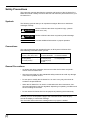
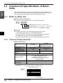
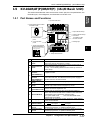
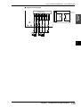
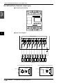
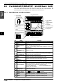
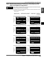
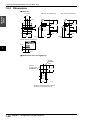
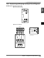
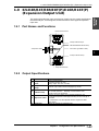
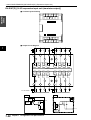
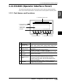
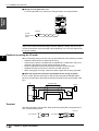
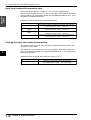
1.11 KV-D20 (Operator interface panel)
1.11 KV-D20 (Operator Interface Panel)
Visual KV
Series
This section describes the name and function of each part, the general specifications, the functional specifications, and dimensions of the operator interface panel.
1.11.1 Part Names and Functions
1 Customized indicator lamps
1
2
3
4
5 Communication port
(provided on rear face)
2 Liquid crystal
display screen
6 Bit guide
7 6 5 4 3 2 1 0
F1
F2
F3
F4
11
3. Customized switches
N o.
N ame
1
Cust omiz ed
indicat or lamps
2
Liquid cry st al
display screen
3
Cust omiz ed
swit ch
4
5
6
4. Setting operation switches
Funct ion
Assigned to special utility relays as follows.
Lamp 1: 2504 Lamp 2: 2505 Lamp 3: 2506 Lamp 4: 2507
When a relay turns ON, the corresponding LED becomes lit.
Displays ladder comments (up to 20 characters) and all devices
in KV Series.
Assigned to special utility relays as follows.
F 1: 2500 F 2: 2501 F 3: 2502 F 4: 2503
When a switch is turned on, the corresponding relay turns ON.
S et t ing operat ion
Changes screen display.
swit ches
RJ-11 Modular connector.
Used for communication between KV basic units while
Communicat ion
connected to the basic unit's communication port with an
port
accessory cable (OP-26487). This port also supplies driving
power for the KV-D20.
Shows the corresponding number of each bit on the KV-I/O
B it guide
monitor screen, the operator screen, or the 8-bit ON/OFF
indication in the device mode.
Chapter 1 Configuration and Specifications
1-59