1
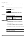
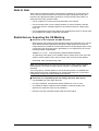
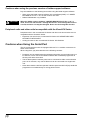
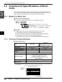
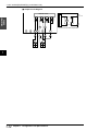
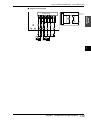
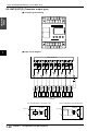
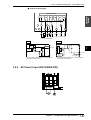
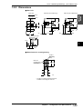
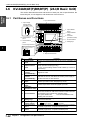
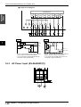
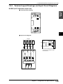
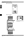
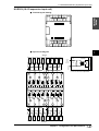
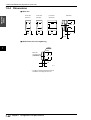
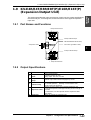
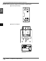
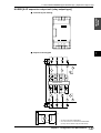
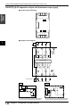
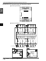
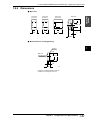
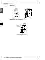
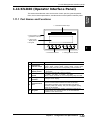
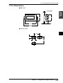
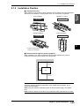
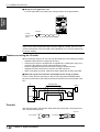
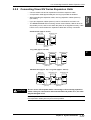
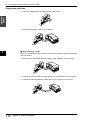
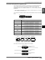
2.1 Installation Environment
■ Wiring for a DC type basic unit
For a DC type basic unit, perform the wiring as shown in the figure below.
Visual KV
Series
KV-10DR
001
000
C1
002
KV-10DR
003
004
005
IN
503
OUT
C2
EYENCE
0ch
0
1
0
1
2
3
2
3
4
5
5ch
501
24V-IN-OV
500
C3
502
C4
Breaker
24 VDC
external power
supply
Note: Connect the power supply to the power supply input terminals with 24 VDC
output, which offers a sufficient margin of power capacity. Usually, the sum of the
current consumption of all connected units multiplied by 1.5 or more is required for
the power capacity.
Cautions on wiring for I/O units
2
When performing wiring for an I/O unit, pay strict attention to the following contents.
•
•
•
•
•
Separate input lines from output lines in wiring.
If the wiring for power is located near I/O signal lines, a malfunction may occur
caused by the effects of a high voltage and large current.
Keep I/O signal lines away from the power wiring by at least 100 mm.
Separate 24 VDC I/O lines from 100 VAC and 200 VAC lines.
When using pipes for wiring, make sure that the pipes are securely grounded.
■ When I/O signal lines cannot be separated from the wiring for power
In such a case, perform grounding on the KV side using batch-shielded cables.
(In some environments, grounding should be performed on the reverse side of the
KV.)
Shielded cable
KV
Sensor
Input
RL
Output
24 VDC
Ground
Terminal
The terminal screws used are M3. When performing wiring with crimp-style terminals, use the following ones.
Unit: mm
6.0 maximum
6.0 maximum
M3
1-68
Chapter 2 System Installation