1
122
• vacon
parameter descriptions
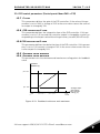
9.17 Modbus RTU
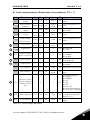
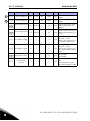
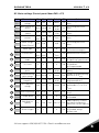
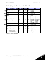
Vacon 20 has a built-in Modbus RTU bus interface. The signal level of the interface
is in accordance with the RS-485 standard.
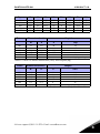
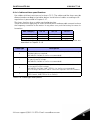
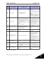
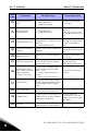
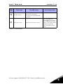
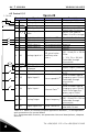
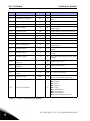
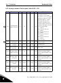
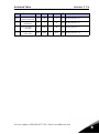
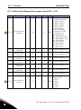
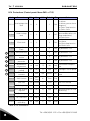
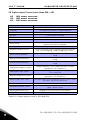
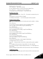
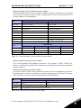
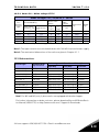
The built-in Modbus connection of Vacon 20 supports the following function codes:
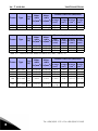
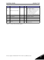
Function
code
Broadcast
messages
Function name
Address
03
Read Holding Registers
All ID numbers
No
04
Read Input Registers
All ID numbers
No
06
Write Single Registers
All ID numbers
Yes
16
Write multiple registers
All ID numbers
Yes
Table 9.3: Modbus RTU
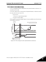
9.17.1 Termination resistor
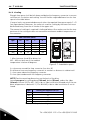
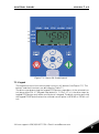
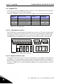
The RS-485 bus is terminated with termination resistors of 120 ohms in both ends.
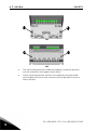
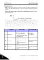
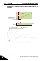
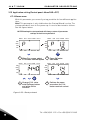
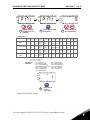
Vacon 20 has a built-in termination resistor which is switched off as a default (presented below). The termination resistor can be switched on and off with the right
hand dip switch located above IO-terminals in the front of the drive (see below).
3
15
6
16
7
18
8
9
R13 R14
22
20
*
26
25
10
A
B
DI
Enco Nor
+10VAI1 GND 24V DI-C DI1 DI2 DI3
ON
J500
R24
23
24
R21 R22
AI2
mA
2
14
V
1
13
AO
mA
5
V
4
RS485
- term
AI2 GND DO- DI4 DI5 DI6 AO DO+
OFF
Figure 9.25: Termination resistor
9.17.2 Modbus address area
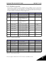
The Modbus interface of Vacon 20 uses the ID numbers of the application parameters
as addresses. The ID numbers can be found in the parameter tables in chapter 8.
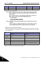
When several parameters / monitoring values are read at a time, they must be consecutive. 11 addresses can be read and the addresses can be parameters or monitoring values.
Tel. +358 (0)201 2121 • Fax +358 (0)201 212205
9