1
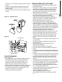
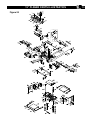
MAINTENANCE
10
ADJUST ROLLERCASE LEVEL
Refer to Parts Illustration
• The rollercase level is checked in factory and should
work properly. However, it can become out of alignment
during shipping and handling.
• If the rollercase (Key No.102) is not level with the base
(Key No. 167), the depth-of-cut will not be even from
side to side. The end result is tapered cut where the
thickness on one side is different from the other side.
This can result from uneven wear of the blade as well.
Check to see blades are in good working order.
• Test run with two test pieces on right and left ends of
the planer to determine the amount needs to be
corrected.
• Carefully place the planer on its back.
• From the bottom of the machine, identify and loose two
socket head bolts (Key No. 181) that secure chain idler
bracket (Key No. 179). (The adjustment can be done
from either side.)
• Release the chain idler bracket (Key No. 179) and loose
the chain (Key No. 186).
• Identify the elevation screws (Key No. 166) and rotate
according to the amount needs to be corrected. Each
complete turn will move that side of rollercase by 1/16”.
• Replace and partially tighten the chain idler bracket
(Key No. 179) and two socket head bolts (Key No. 181).
• Tighten the chain (Key No. 186) with the chain idler
bracket (Key No. 179).
• Tighten the socket head bolts (Key No. 181) completely.
• Sit the planer upright carefully.
• Test run the planer to check the rollercase level
adjustment.
• Repeat the procedures if further adjustment is
necessary.
REPLACE V-BELTS
Refer to Parts Illustration
• There are two V-belts (Key No. 47 and 140) in this
machine.
• To inspect V-belts, the head panel (Key No. 10) needs
to be removed.
• Remove socket pan head screw and washer (Key No. 1
and 2) on the rollercase elevation crank handle. Remove
the crank handle.
• Remove the thickness pre-set gauge control knob (Key
No. 206). Simply pull it off.
• Remove 4 screws (Key No. 15) on the head panel and
removed the head panel (Key No. 10).
• Remove right side panel (Key No. 205).
• Now both V-belts (Key No. 47 and 140) are visible.
Check the belt tension and any wear, tear, or crack on
the V-belts. Loose or damaged V-Belts need to be
replaced. Replace with new V-belts only.
• To replace V-belts, gently remove the used V-belts by
turning the pulleys and gradually sliding the V-belts off
the pulleys (Key No. 46, 138 and 142).
• To install new V-belt, slide the new V-belt onto pulleys
gradually while rotating the pulleys. Check to see the
V-belt sits securely on both pulleys.
• Repeat the same procedure to replace another V-belt if
necessary.
• Replace right side panel (Key No. 205).
• Replace head panel (Key No. 10). Make sure the side
panels (Key No. 205) are in alignment.
• Tighten 4 screws (Key No. 15) on the head Panel.
• Replace the rollercase elevation crank handle. Secure
with socket pan head screw and washer (Key No. 1
and 2).
• Replace the thickness pre-set gauge control knob (Key
No. 206).
CLEAN AND LUBRICATION
• Vacuum clean the planer machine to remove wood
chips, saw dust, and debris.
• Use cleaner solution to remove resin and grease
residue.
• Check and empty dust collection bag.
• Remove saw dust, wood chips, and grease from chains
and gears.
• The bearings in motor and cutterhead units are
permanently sealed in factory and should require no
further lubrication.
• Four components require regular lubrication: rollercase
elevation screws (2x), rollercase lock cam, the columns
(4x), and the feed roller chain drive. Remove the top and
both side panels to access these components.
• Remove old grease residues, with minerals spirits if
necessary, then apply a coat of light grade
multi-purpose grease.
• Chain drive should be cleaned before lubrication. Use
spray oil to lubricate the chain. The chain should be
wiped dry after the lubricant has had enough time to
penetrate the links.
• The work table and extension table can be coated with
very thin lubricating wax to protect the surface from rust
and to facilitate smooth feed during operation.