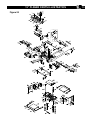
1
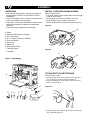
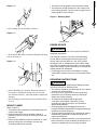
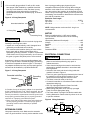
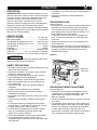
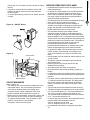
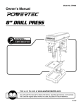
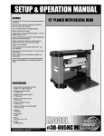
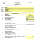
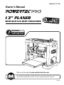
Model No. PL1300
Owner’s Manual
13” PLANER
WITH BUILT-IN DUST COLLECTION
QUESTION...
0
1•877•393•7121
Visit us on the web at www.southerntechllc.com
You will need this manual for safety instructions, operating procedures, and warranty.
Put it and the original sales invoice in a safe, dry place for future reference.
09-0911
TABLE OF CONTENTS
SECTION
PRODUCTION
SPECIFICATIONS
PAGE
SAFETY RULES
1
Horsepower (Maxmum Developed)........................... 2.4 HP
Voltage..........................................................................120 V
Work Preparation
Work Area Preparation
Tool Maintenance
Tool Operation
Amperes..............................................................................1
5
Hertz...................................................................................60
ASSEMBLY
2
Motor RPM.........................................................17,500 RPM
Unpacking
Install Elevation Crank Handle
Attach Dust Collection Bag
Mount Planer
Power Source
Grounding Instructions
Extension Cords
Electrical Connections
OPERATION5
Table Size.......................................................13” x 10-1/4”
Blade Width....................................................................13”
Maximum Depth of Cut................................................3/32”
Cuts per Minute........................................................16,000
Dust Collection Port....................................................2-1/2”
5
Description
Specifications
Safety Precautions
Rollercase Lock
Rollercase Height Adjustment
Depth of Cut
Thickness Pre-set Gauge
ON/OFF Switch
Circuit Breaker
Before Operating the Planer
Operate the Planer
MAINTENANCE
Phase............................................................................Single
9
Check and Replace the Blades
Inspect and Replace the Motor Brushes
Adjust Rollercase Level
Replace V-Belt
Clean and Lubrication
TROUBLESHOOTING
11
PARTS ILLUSTRATION &
LIST
13
WARRANTY
17
SAFETY RULES
WARNING
For your own safety, read and understand all warnings
and operating instructions before using any tool or
equipment.
WARNING
Some dust created by operation of power tool contains
chemicals known to the State of California to cause
cancer, birth defects or other reproductive harm.
To reduce your exposure to these chemicals: work in a
well ventilated area and work with approved safety
equipment. Always wear OSHA/NIOSH approved,
properly fitting face mask or respirator when using such
tools.
WARNING
Failure to follow these rules may result in serious personal
injury. Remember that being careless for even a fraction
of a second can result in severe personal injury.
WORK PREPARATION
• Wear proper apparel. Do not wear loose clothing,
gloves, neckties, rings, bracelets or other jewelry which may get caught in moving parts of the tool.
• Nonslip protective footwear is recommended.
• Wear protective hair covering to contain long hair.
• Wear eye and hearing protection. Always use safety
glasses. Eye protection equipment should comply with
ANSI Z87.1 standards. Hearing equipment should
comply with ANSI S3.19 standards.
• Wear face mask or dust mask if operation is dusty.
• Be alert and think clearly. Never operate power tools when tired, intoxicated or when taking medications that cause drowsiness.
WORK AREA PREPARATION
• Keep work area clean. Cluttered work areas and
benches invite accidents.
• Work area should be properly lighted.
• Do not use the machine in a dangerous environment.
The use of power tools in damp or wet locations or in
rain can cause shock or electrocution.
• Three-prong plug should be plugged directly into
properly grounded, three-prong receptacle.
• Use the proper extension cord. Make sure your
extension cord is in good condition and should have a
grounding prong and the three wires of
extension cord should be of the correct gauge.
• Keep children and visitors away. Your shop is a potentially dangerous environment. Children and visitors can
be injured.
•Make your workshop childproof with padlocks, master
switches or remove switch keys to prevent any unintentional use of power tools.
1
TOOL MAINTENANCE
• Turn the machine "OFF", and disconnect the machine
from the power source prior to inspection.
• Maintain all tools and machines in peak condition. Keep
tools sharp and clean for best and safest performance.
• Follow instructions for lubricating and changing
accessories.
• Check for damaged parts. Check for alignment of
moving parts, binding, breakage, mounting and any
other condition that may affect tool's operation.
• Poorly maintained tools and machines can further
damage the tool or machine and/or cause injury.
• A guard or any other part that is damaged should be
repaired or replaced. Do not perform makeshift repairs.
TOOL OPERATION
• Avoid accidental start-up. Make sure that the tool is in the “OFF” position before plugging in.
• Use the right tool for your job. Do not force your
tool or attachment to do a job for which it was not
designed.
• Disconnect tool when changing parts.
• Don't force the workpiece on the machine. Damage to
the machine and/or injury may result.
• Never leave tool running unattended. Turn the power off and do not leave tool until it comes to a complete stop.
• Do not overreach. Loss of balance can make you fall
into a working machine, causing injury.
• Never stand on tool. Injury could occur if the tool tips, or
if you accidentally contact the cutting tool.
• Know your tool. Learn the tool’s operation, application and specific limitations before using it.
• Use recommended accessories. Use of improper accessories may cause damage to the machine or injury
to the user.
• Handle workpiece correctly. Keep hands away from
moving parts.
• Turn tool off if it jams.
CAUTION: Think safety! Safety is a combination of operator common sense and alertness at all times when tool is
being used.
WARNING
Do not attempt to operate tool until it is completely
assembled according to the instructions.
ASSEMBLY
2
UNPACKING
• Check freight damage before opening the package. If
freight damage is noticed, file claim with the carrier
immediately.
• Check for complete part list. Contact Customer Service
Center immediately for missing parts.
• This Planer comes mostly assembled. It requires some
additional assembling, installation, and adjustment
before use.
• Locate the following parts before assembling:
A. Planer
B. Elevation Crank Handle Assembly
C. 6mm Flat Washer
D. 6-1.0 x 20mm Socket Pan Head Bolt
E. 4mm Hex Wrench
F. Dust Chute
G. Magnet (2)
H. Dust Collection Wire
I. Dust Bag Clamp
J. Dust Bag
INSTALL ELEVATION CRANK HANDLE
Refer to Figure 2 and 3
• The planer handle can be installed either to the top-right
or top-left of the planer.
• Remove plug from the end of elevation screw (a)
• Insert handle (b) onto elevation screw top (a).
• Secure handle with bolt using the enclosed wrench (c).
Figure 2
a
Figure 3
c
b
0
Figure 1 Unpackaging
ATTACH DUST COLLECTION BAG
A
Refer to Figure 1 and 4
• Install the Dust Chute (F) by slipping it over the Dust
Port. Tighten the screw on the Dust Chute (F).
• Insert Dust Bag Wire (H) through a small hole on the
sleeve of Dust Bag (J).
H
B
C D
G
E
F
Figure 4 - 1
I
J
• Draw the open end of Dust Bag (J) sleeve through the
ring of Dust Bag Wire (H).
• The planer must be bolted to a firm and level surface.
• There must be enough clearance for the moving work
piece during operation. There must be enough room for
safety operation of the machine.
ASSEMBLY
Figure 4 - 2
Figure 5 – Mounting Holes
3
• Place Clamp (I) over Dust Bag (J) Sleeve.
Figure 4 - 3
Mounting Holes
POWER SOURCE
WARNING
• Slide Sleeve with Clamp (I) and Dust Bag Wire (H) Ring
over Dust Chute (F).
Figure 4 - 4
Do not connect to the power source until the machine is
completely assembled.
The machine is wired for 120 volts, 60 HZ alternating
current. Before connecting the machine to the power
source, make sure the switch is in the "OFF" position.
Running the unit on voltages which are not within range
may cause overheating and motor burn-out. Heavy loads
require that voltage at motor terminals be no less than the
voltage specified on nameplate.
• Power supply to the motor is controlled by a locking
rocker switch. Remove the key to prevent unauthorized
use.
GROUNDING INSTRUCTIONS
WARNING
• Secure Dust Bag (J) in position. Rotate the handle on
the Clamp (I) to adjust the clamp size so it can slide
over the Dust Chute (F). Press the handle to tighten the
Clamp (I).
• The Dust Bag (J) should be secured on the Dust Chute
(F) now.
MOUNT PLANER
Refer to Figure 5
• The planer must be installed in a well-lighted area with
correct power supply.
• Eight mounting holes are on the base of planer. If
pre-drilled holes do not exist on the bench surface, drill
four holes.
• Planer can be installed on either a workbench or a tool
stand by using bolts, lock washers, and hex nuts.
(mounting hardware not included)
Improper connection of equipment grounding conductor
can result in the risk of electrical shock.
• The machine should be grounded while in use to protect
operator from electrical shock.
• In the event of an electrical short circuit, grounding
reduces the risk of electrical shock by providing an
escape wire for the electricity.
• This machine is equipped with an approved
3-conductor cord rated at 150V and a 3-prong
grounding type plug (Figure 6) for your protection
against shock hazards.
• Grounding plug should be plugged directly into a
properly installed and grounded 3-prong grounding-type
receptacle, as shown (Figure 6)
• The plug must be plugged into an outlet that is properly
installed and grounded in accordance with all local
codes and ordinances.
• Check with a qualified electrician or service personnel if
these instructions are not completely understood or if in
doubt as to whether the tool is properly grounded.
ASSEMBLY
• Do not modify plug provided. If it will not fit in outlet,
have proper outlet installed by a qualified electrician.
Use only 3-wire extension cords, that have 3-prong
grounding type plugs and matching 3-conductor
receptacles that accept the machine's plug, as show in
Figure 6
Figure 6 - 3-Prong Receptacle
4
Grounded outlet Box
have 3-prong grounding type plugs and 3-pole
receptacles which accept the tool plug. When using an
extension cord, make sure to use one heavy enough to
carry the current of the machine. An undersized cord will
cause a drop in the voltage, resulting in loss of power and
overheating. Use the table to determine the minimum wire
size (A.W.G.) extension cord.
Extension Cord Length
Wire Size . . . . . . . . . . . . . . . . . . . . . . . . . . . . . . . . A.W.G.
Up to 25 ft. . . . . . . . . . . . . . . . . . . . . . . . . . . . . . . . . . . . 18
25 to 50 ft. . . . . . . . . . . . . . . . . . . . . . . . . . . . . . . . . . . . 16
NOTE: Using extension cords over 50 ft. long is not
recommended.
3 - Prong Plug
MOTOR
Grounding Prong
WARNING
Do not permit fingers to touch the terminals of plug when
installing or removing from outlet.
• Inspect tool cords periodically, and if damaged, have
repaired by an authorized service facility.
• The conductor with insulation having an outer surface
that is green with or without yellow stripes is the
equipment-grounding conductor. If repair or replacement
of the electric cord or plug is necessary, do not connect
the green (or green and yellow) wire to a live terminal.
A temporary 3-prong to 2-prong grounding adapter (see
Figure 7) may be used to connect this plug to a matching
2-conductor receptacle as shown in figure 7. The temporary adapter should be used only until a properly grounded outlet can be installed by a qualified electrician.
Figure 7 - 3-Prong Receptacle
Grounded outlet Box
Adapter
Grounding
Means
In Canada, the use of temporary adapter is not permitted
by the Canadian Electric Code. Where permitted, the rigid
green tab or terminal on the side of the adapter must be
securely connected to a permanent electrical ground such
as a properly grounded water pipe, a properly grounded
outlet box or a properly grounded wire system.
• Many cover plate screws, water pipes and outlet boxes are not properly grounded. To ensure proper ground, grounding means must be tested by a qualified
electrician.
EXTENSION CORDS
Use proper extension cords. Make sure the extension
cord is in good condition. Use only 3-wire extension cords
Planer is supplied with a 2.4 HP motor installed.
The 120 Volt AC universal motor has the following
specifications:
Horsepower (Maximum Developed) . . . . . . . . . . . .2.4 HP
Voltage . . . . . . . . . . . . . . . . . . . . . . . . . . . . . . . . . . . . .120
Amperes . . . . . . . . . . . . . . . . . . . . . . . . . . . . . . . . . . . . .15
Hertz. . . . . . . . . . . . . . . . . . . . . . . . . . . . . . . . . . . . . . . .60
Phase . . . . . . . . . . . . . . . . . . . . . . . . . . . . . . . . . . . Single
Cutterhead RPM . . . . . . . . . . . . . . . . . . . . . . . . . . . .8,000
ELECTRICAL CONNECTIONS
WARNING
• Turn the switch off and disconnect the machine from
power source before performing any repair or
maintenance work.
• Some electrical wiring and connection work must be
performed by qualified electrician in accordance with
local regulations.
• Scheme of the motor and electric wiring inside this
machine is shown in Figure 8
• There is a green grounding wire fastened to the frame of
the machine to provide Shock Protection. Do not
disconnect the Grounding Wire from the frame.
• The Motor is rated for used at 120 Volts.
• Connect this machine to 3-Conductor Power outlet with
appropriate rating only.
• Use only 3-pronged Extension Power Cord with
appropriate rating with this machine.
• When change the power cord, use only 3-pronged
Power Cord with appropriate rating.
• The Power switch is a Single Pole Rocker switch with
Locking Mechanism. Remove the Key when not in use
to prevent accidents.
Figure 8 Wiring Schematic
OPERATION
DESCRIPTION
POWERTEC PRO 13” planer handles workpiece up to 13”
(330 mm) wide and 6” (152 mm) thick. The planer features
a powerful 15 amp, 2.4 HP (max. developed) motor with
overload protection, built-in dust collection for fast
removal of wood chips, rollercase lock for uniform
thickness, depth-of-cut gauge and 6 pre-set depth gauge
setting for convenient and consistent set-up, sturdy
four-post design for snipeless planing, easy blade change,
top rollers for workpiece return and larger extension tables
with rollers for smooth operation.
SPECIFICATIONS
Maximum Cutting Width ………………..…….13” (330 mm)
Max Cutting Height ………………………..……6” (152 mm)
Cutting Depth for Width from 0” to 6”……....3/32” (2.4 mm)
Cutting Depth for Width from 6” to 13”……..1/16” (1.6 mm)
Cuts per Minute…………………………………….….16,000
Feed Rate ………………………………………….…19 FPM
Table Material ………………………………..Stainless Steel
Table Size ……………….13” x 10-1/4” (330 mm x 260mm)
Table Size with Extension.....13” x 24-5/8” (330 mm x 625 mm)
WARNING
5
• Turn switch off and disconnect power whenever planer
is not in use.
• Keep planer maintained. Follow maintenance
instructions.
ROLLERCASE LOCK
Refer to Figure 9
• Rollercase Lock is the locking mechanism that prevents
rollercase from movement during planning operation.
The rollercase lock lever is located on the right side
panel, between the side panel and the rollercase. It is
easily visible from the front of planer.
• To lock the rollercase, pull down the rollercase lock
lever. To unlock the rollercase, lift up the Rollercase
Lock Lever.
• Always use rollercase lock for smooth planning and
uniform thickness.
• Always unlock the rollercase lock before adjusting the
rollercase height. The Locking mechanism will wear out
prematurely if excessive force is used to move the
rollercase while locked.
Figure 9
For our own safety, read the entire operating manual and
safety instructions before using this tool.
SAFETY PRECAUTIONS
• Be aware of general power tool safety. Make sure all the
safety rules are understood.
• Disconnect the machine from power source whenever
adjusting or replacing any parts.
• Do not plug in unless switch is in the “OFF” position.
• Keep hands away from all moving parts.
• Wear eye protection or face shield during operation.
• Make sure all mobile parts move freely and are free
from interference.
• Keep blades sharp, aligned and properly attached
cutterhead.
• Properly secure the blades in the cutterhead.
• Never turn the machine “ON” with the workpiece
contacting the cutterhead.
• Never make cuts deeper than 3/32” (2.4mm) to prevent
kickback.
• Do not force cut. Slowing or stalling will overheat the
motor.
• Do not perform planing on workpiece shorter than 5”,
narrower than ¾”, wider than 13” or less than 1/8” thick.
• Properly support long or wide workpieces.
• Do not perform a workpiece that is warped, contains
knots, or is embedded with foreign objects (nails,
staples, etc) to prevent kickback.
• Do not feed a workpiece into the planer outfeed table.
• Do not allow anyone to stand or cross in line of
cutterhead rotation. Kickback or thrown debris will travel
in this direction.
Rollercase
Lock Lever
ROLLERCASE HEIGHT ADJUSTMENT
Refer to Figure 10
• Rollercase is the centerpiece of the planer machine.
It contains motor, cutterhead with blades, infeed and
outfeed rollers, dust collection assembly, and
depth-of-cut gauge.
• Unlock the rollercase lock before moving the rollercase
up or down.
• The rollercase can be moved up or down precisely by
rotating the elevation crank handle on the top of planer
machine. The elevation crank handle can be installed
on either right or left side of the planer top. One
complete turn of elevation crank handle is equivalent to
1/16” movement of rollercase in either direction.
Elevation Crank Handle
0
Elevation
Depth-of-Cut Gauge
DEPTH OF CUT
Refer to Figure 11
• Thickness pre-set gauge is a knob with scale that shows
six settings: 1/8”, ¼”, ½”, ¾”, 1”, and 1-1/4”. It is located
at bottom of right side panel, on right side of the planer
machine.
1
2/ ”
THICKNES PRE-SET GAUGE
Figure 11
1/
4”
1/
8”
Refer to Figure 10
• The depth-of-cut is the thickness of wood material
removed from the surface of workpiece during each
pass. The depth-of-cut is determined by the relative
position of rollercase to the top of workpiece.
Depth-of-cut can be easily measured and adjusted with
depth-of-cut gauge.
• Depth-of-cut gauge is the small measuring device
located on the right lower corner of rollercase front. The
reading ranges from 0” to 3/32”.
• To use the depth-of-cut gauge, place the workpiece
under the gauge. Crank down the rollercase until it
touches the workpiece. Now watch the gauge while
carefully move the rollercase up and down, until the
desired depth-of-cut reading appears.
• To protect long use life of motor and cutterhead unit, the
recommended maximum depth-of-cut are:
3/32” for workpiece up to 6” wide
1/16” for workpiece from 6” to 13” wide
• Depth-of-cut gauge is calibrated in factory and should
have reasonable accuracy. For woodworking of
precision, use of calipers after each planning is
recommended.
3 / 4”
Figure 10
OPERATION
• Use thickness pre-set gauge to set the desired thickness of the final finished product.
• Thickness pre-set gauge works by stopping the rollercase from moving any lower once it reaches the pre-set
thickness. The workpiece may need to pass the planer
several times before reach the desired final thickness.
But the thickness pre-set gauge will ensure the final
finish product is not over done. This makes the whole
planing process easier and faster. This is especially
useful and efficient when processing several pieces of
wood product with the same desired thickness.
• Thickness pre-set gauge is calibrated in factory and
should have reasonable accuracy. For woodworking of
precision, use of calipers after each planning is
recommended.

To Set the Thickness Pre-set Gauge:
• With the machine turned off, raise the rollercase until it
is slightly higher than the intended workpiece.
• Place the workpiece below the Rollercase to check that
it can pass under the rollercase easily.
• Turn the control knob of thickness pre-set gauge to the
desired setting.
• Now the rollercase will stop moving lower once it
reaches the set thickness.

To Reset the Thickness Pre-set Gauge:
• With the machine turned off, use elevation crank handle
to raise the rollercase by a few turns. This is to ensure
the gauge is not jammed and is ready to be reset.
• Repeat the same procedures as to set the thickness
pre-set gauge.
11/8”
1”
6
• There is an elevation scale at the front of left side panel.
It has a pointer with English and Metric scale. The
reading is the height of cutterhead from the table
platform. Therefore, the elevation scale setting
represents the approximate thickness of the workpiece
after planning.
• Elevation scale is calibrated in factory and should have
reasonable accuracy. For woodworking of precision, use
of calipers after each planning is recommended.
ON/OFF SWITCH
Refer to Figure 12 and 13
The ON/OFF switch is located on the front of planer. To
turn the machine ON, pull the switch to the up position. To
turn the machine OFF, push the switch to the down
position.
NOTE: When the machine is not in use, the machine
should be locked in the “OFF” position to prevent
unauthorized use.
• To lock the machine, turn the switch to the “OFF”
position.
Figure 12 – ON/OFF Switch
Figure 13
0
Circuit Breaker
ON/OFF Switch
CIRCUIT BREAKERR
Refer to Figure 13
• This machine has a circuit breaker installed next to the
main power switch. The circuit breaker protects the
motor unit by shutting off the power supply when
excessive electric current is detected. If the circuit
breaker is tripped, the machine will not power on.
• Before reset of circuit breaker, check motor, switch, and
line connection for short circuit or faulty components.
• To reset the circuit breaker, Turn the switch to "OFF"
position. Then press the circuit breaker
reset button next to the main switch.
BEFORE OPERATING THE PLANER
•Understand the machine function and observe all the
safety measurement.
•In general, the desired depth-of-cut and final thickness
of workpiece are determined before planing. Since
there is limit of maximum depth-of-cut, the workpiece
may have to pass the machine several times before
reach the desired final thickness.
•The Rollercase has to be lowered manually before each
pass, if more than one pass are necessary.
•The planer machine setting involves readings of
elevation scale, depth-of-cut gauge, thickness pre-set
gauge, and operation of rollercase elevation crank
handle and thickness pre-set control knob.
•The rollercase elevation crank handle controls
rollercase position in height. In combination with the
depth-of-cut gauge, the amount of wood material to be
removed (depth-of-cut) in each pass can be determined.
Thickness of the remaining workpiece after planing (final
thickness) is observed in elevation scale. The thickness
pre-set gauge and control knob are used to stop
rollercase automatically when it reaches the
pre-determined final thickness. It prevents overcut and
makes the whole planing process easier and faster.
•In general, thin depth-of-cut produces better outcome:
smooth surface, even thickness, less kickback, less
snipe, even thickness, less wear on cutterhead and
motor.
•Set thin depth-of-cut for hardwood, wide workpiece, and
uneven surface.
•This planer machine is designed to process natural
wood material only.
•Remove glue and any foreign objects from the
workpiece before planing.
•Avoid wood stock with many or large knots.
•Avoid wood stock with excessive twisting, cupping, or
bowing.
•If necessary, process one side with jointer machine first
to obtain at least one flat surface before using the planer
machine.
•For better outcome, plane both sides of wood board with
½ of depth removed from each side. This will produce
two smooth surfaces with equal amount of moisture
content. The board is less likely to warp when it dries
naturally.
•Test cut with similar wood material for better accuracy.
•The Minimal length of workpiece that can be processed
is 5”. The minimal width is ¾”. The minimal thickness is
1/8”. (This is not to be confused with depth-of-cut.)
•The maximal width of workpiece that can be processed
is 13”. The maximal thickness is 6”.
•To protect long use life of motor and cutterhead unit, the
recommended maximum depth-of-cut are:
3/32” for workpiece up to 6” wide
1/16” for workpiece from 6” to 13” wide
•Use additional roller stand for workpiece longer than
24”.
OPERATION
Pull the key out. The switch cannot be turned on without
the key.
• If the key is removed when the switch is at the "ON"
position, the switch can be turned off but cannot be
turned on again.
• To unlock, place the key into the slot on switch unit until
it snaps.
7
OPERATION
8
OPERATE THE PLANER MACHINE
• Always use safety wears and observe safety rules.
• Never stand directly in the pathway of the workpiece,
including infeed and outfeed, to avoid injury. The
operator should stand on the side of the elevation crank
handle.
• Feed the workpiece “WITH The Grain” as much as
possible. That is, at the contact point, the grain points to
the same direction as that of rotating cutterhead. For
this planer machine, the grain direction on the top of
workpiece should point toward the front of the machine.
• Place the workpiece on the infeed table. The surface to
be planed faces up.
• With the planer properly set up, turn the machine on.
• Hold the workpiece firmly and advance toward the
infeed roller slowly.
• Stop pushing or pulling the workpiece once it is
engaged by the infeed roller.
• The infeed roller will move the workpiece automatically
through the planer.
• For long workpiece, gently support the weight of the
workpiece while it is moved into and out of the planer to
stabilize the workpiece and decrease snipe.
• Move to the back of machine to receive the workpiece.
Do not pull.
• Use the Return Roller on top of Planer to help transport
big workpiece back to infeed side.
• Use the entire width of the cutterhead to avoid uneven
wear of knifes.
• For precision woodwork, measure thickness with
calipers after each planing.
MAINTENANCE
WARNING
9
Figure 14
Turn the switch to the OFF position and disconnect the
machine from power source before any maintenance.
CHECK AND REPLACE THE BLADES
Refer to Figure 15 and 16
• Locate the blade cover on the back of planer. Loose
socket head bolts with L wrench and remove the blade
cover.
• Identify the cutterhead inside. Watch for TWO sharp
blades on the cutterhead.
• Without touching the blades, carefully turn the
cutterhead until it stops by the self-engaging latch.
• Use L Wrench to remove 6 bolts on the blade assembly.
• Attach 2 provided magnets to the gib and carefully
removed it.
• Attach 2 provided magnets to the blades and carefully
removed it.
• Check to see if the blade is dull, worn, nicked, torn, and
uneven. These can result in poor performance such as
fuzzy grain, chipped grain, raised grain, raised edge,
and uneven cut.
• Replace with new blades in pairs only. Never mix new
blade with old blade on one cutterhead. Never mix
blades with different degrees of wear. Never use a
blade where unbalanced wear from side to side is
present.
• To replace with the new blade, use the 2 provided
magnets to transfer the blade onto the cutterhead.
Position the blade so it sits securely on the two pins.
• Use the 2 provided magnets to transfer the gib onto the
blade. Position the gib so the 6 holes is aligned with the
holes on the cutterhead.
• Tighten and secure with 6 bolts.
• To access the other blade assembly, gently pull and
hold the latch on the side of cutterhead to release it.
Once the cutterhead rotates, release the latch.
• Without touching the blades, carefully turn the
cutterhead until it stops the self-engaging latch.
• Repeat the same procedure to check and replace the
other blade.
• Replace the blade cover and secure with the socket
head bolts.
Socket Head Bolt
Figure 15
Magnets
Gib
Blade
Cutterhead
Latch
Pin
INSPECT AND REPLACE THE MOTOR
BRUSHES
• Turn the switch in the “OFF” position and disconnect the
planer machine from the power source.
• Inspect the motor brushes after every 100 hours of use.
Brush life varies, depending on the motor loads.
• Replace the motor brushes in set (two brushes) only.
Replace with new parts only.
• To inspect motor brushes, unscrew brush caps on the
sides of motor. There are two caps, one on each side of
motor.
• Remove brush assembly from motor.
• Replace motor brushes if the length of carbon has been
worn to less than 3/8”, or if the springs are worn, or if the
motor does not run smoothly.
• Replace with new motor brush assembly.
• Replace the brush cap and tighten the screw.
• Repeat the same procedure on the other side of motor.
MAINTENANCE
10
ADJUST ROLLERCASE LEVEL
Refer to Parts Illustration
• The rollercase level is checked in factory and should
work properly. However, it can become out of alignment
during shipping and handling.
• If the rollercase (Key No.102) is not level with the base
(Key No. 167), the depth-of-cut will not be even from
side to side. The end result is tapered cut where the
thickness on one side is different from the other side.
This can result from uneven wear of the blade as well.
Check to see blades are in good working order.
• Test run with two test pieces on right and left ends of
the planer to determine the amount needs to be
corrected.
• Carefully place the planer on its back.
• From the bottom of the machine, identify and loose two
socket head bolts (Key No. 181) that secure chain idler
bracket (Key No. 179). (The adjustment can be done
from either side.)
• Release the chain idler bracket (Key No. 179) and loose
the chain (Key No. 186).
• Identify the elevation screws (Key No. 166) and rotate
according to the amount needs to be corrected. Each
complete turn will move that side of rollercase by 1/16”.
• Replace and partially tighten the chain idler bracket
(Key No. 179) and two socket head bolts (Key No. 181).
• Tighten the chain (Key No. 186) with the chain idler
bracket (Key No. 179).
• Tighten the socket head bolts (Key No. 181) completely.
• Sit the planer upright carefully.
• Test run the planer to check the rollercase level
adjustment.
• Repeat the procedures if further adjustment is
necessary.
REPLACE V-BELTS
Refer to Parts Illustration
• There are two V-belts (Key No. 47 and 140) in this
machine.
• To inspect V-belts, the head panel (Key No. 10) needs
to be removed.
• Remove socket pan head screw and washer (Key No. 1
and 2) on the rollercase elevation crank handle. Remove
the crank handle.
• Remove the thickness pre-set gauge control knob (Key
No. 206). Simply pull it off.
• Remove 4 screws (Key No. 15) on the head panel and
removed the head panel (Key No. 10).
• Remove right side panel (Key No. 205).
• Now both V-belts (Key No. 47 and 140) are visible.
Check the belt tension and any wear, tear, or crack on
the V-belts. Loose or damaged V-Belts need to be
replaced. Replace with new V-belts only.
• To replace V-belts, gently remove the used V-belts by
turning the pulleys and gradually sliding the V-belts off
the pulleys (Key No. 46, 138 and 142).
• To install new V-belt, slide the new V-belt onto pulleys
gradually while rotating the pulleys. Check to see the
V-belt sits securely on both pulleys.
• Repeat the same procedure to replace another V-belt if
necessary.
• Replace right side panel (Key No. 205).
• Replace head panel (Key No. 10). Make sure the side
panels (Key No. 205) are in alignment.
• Tighten 4 screws (Key No. 15) on the head Panel.
• Replace the rollercase elevation crank handle. Secure
with socket pan head screw and washer (Key No. 1
and 2).
• Replace the thickness pre-set gauge control knob (Key
No. 206).
CLEAN AND LUBRICATION
• Vacuum clean the planer machine to remove wood
chips, saw dust, and debris.
• Use cleaner solution to remove resin and grease
residue.
• Check and empty dust collection bag.
• Remove saw dust, wood chips, and grease from chains
and gears.
• The bearings in motor and cutterhead units are
permanently sealed in factory and should require no
further lubrication.
• Four components require regular lubrication: rollercase
elevation screws (2x), rollercase lock cam, the columns
(4x), and the feed roller chain drive. Remove the top and
both side panels to access these components.
• Remove old grease residues, with minerals spirits if
necessary, then apply a coat of light grade
multi-purpose grease.
• Chain drive should be cleaned before lubrication. Use
spray oil to lubricate the chain. The chain should be
wiped dry after the lubricant has had enough time to
penetrate the links.
• The work table and extension table can be coated with
very thin lubricating wax to protect the surface from rust
and to facilitate smooth feed during operation.
TROUBLESHOOTING
SYMPTON
POSSIBLE CAUSE(S)
Motor will not start
1. Low voltage
2. Short circuit in line cord or plug
Motor stalls or fails to reach
full speed
1. Power overload
2. Low voltage from power supply
3. Undersized line cord
Motor overheats
1. Motor overloaded
Snipe
1. Reduce workload on the power supply
2. Check power supply for proper voltage
3. Use line cord of adequate size or reduce
length of wiring
4. Motor overload
4. Reduce load on motor
5. Short circuit or loose connection in 5. Inspect the connection in motor for loose or
motor
shorted connection
6. Incorrect fuses or circuit breakers 6. Replace with correct fuses or circuit breakers
7. Wood chips clogged
7. Inspect chip blower assembly and fan belt.
Remove excessive wood chips
1. Reduce load on motor. Turn off the machine
until motor cools down
2. Remove dust build-up
1. Motor overload
2. Inadequate capacity of circuit
breaker
3. Circuit overload
4. Blades are dull
1. Reduce load on motor
2. Replace with correct circuit breaker
1. Inadequate support of workpiece
1. Support long workpiece with additional
platform
2. Replace blades
3. Push workpiece gently during operation
4. Adjust table and rollercase level properly
2. Blades are dull
3. Uneven force on cutterhead
4. Rollercase is not level with planer
base
5. Workpiece is not butted properly
Surface not smooth
SOLUTIONS
1. Check power supply for proper voltage
2. Inspect line cord and plug for faulty
insulation or shorted connection
3. Short circuit in motor
3. Inspect connection on motor
4. Open circuit or loose connection in 4. Inspect connection on motor
motor
5. Incorrect fuses or circuit breakers 5. Replace with correct fuses or circuit
breakers
6. Defective switch
6. Replace switch
7. Defective capacitor
7. Replace capacitor
8. Motor overload results in circuit
8. Turn the machine off and reset overload
breaker tripped
protection.
2. Excessive dust build-up results in
decreased air circulation
Frequent tripping of circuit
breaker
11
1. Blades are dull
2. Fuzzy grain due to high moisture
content in wood
3. Torn grain due to blades cutting
against grain
4. The cut is too deep
3. Reduce circuit load
4. Sharpen or replace blades
5. Butt end to end each workpiece as it passes
through planer
1. Replace blades
2. Use dry wood
3. Change direction and feed workpiece along
grain
4. Decrease depth of cut
Uneven thickness from side to Rollercase is not positioned level with Adjust table and rollercase level properly
side
planer base
TROUBLESHOOTING
12
SYMPTON
POSSIBLE CAUSE(S)
SOLUTIONS
Difficulties in adjusting
rollercase elevation
1. Rollercase lock is engaged
2. Worn elevation screws
3. Dirty elevation screws or columns
1. Release rollercase lock
2. Replace elevation screws
3. Clean and lubricate elevation screws and
columns
4. Clean and lubricate chains and sprockets
5. Adjust table and rollercase level properly
4. Dirty chains or sprockets
5. Rollercase is not positioned level
with planer base
6. Friction between rollercase and
covers
6. Clean and adjust rollercase
Wood thickness does not
match depth of cut setting
Indicator is not set correctly
Adjust and tighten indicator properly
Chain jumping
1. Worn chains
2. Worn Sprockets
1. Replace chains
2. Replace sprockets
Belt slipping
Belt is loose
Replace V-belt
Reollercase cannot be
lowered to the desired height
Workpiece thickness gauge setting
limits rollercase movement
Change thickness gauge setting
Excessive dust in air
1. Leak in bag or hose connections
2. Broken dust bag
1. Check bag and hose connections
2. Check dust bag and bag clamp
Excessive fan noise
1. Loose fan assembly
2. Large wood chips stuck in fan
housing
1. Inspect fan assembly and tighten fan screws
2. Turn machine off, remove blade guard, and
clean the chamber
13" PLANER PARTS ILLUSTRATION
Figure 20
13
13" PLANER PARTS LIST
14
Key No.
1
2
3
4
5
6
7
8
9
10
11
12
13
14
15
16
17
18
19
20
21
22
23
24
25
26
27
28
29
30
31
32
33
34
35
36
37
38
39
40
41
42
43
44
45
46
47
48
49
50
51
52
53
54
55
56
57
58
59
Part No.
Description Specification
PL1300001 Socket Pan Head Screw
M6xP1.0x20L
PL1300002 Flat Washer
ø6.3xø16x1.5T
PL1300003 Handle PL1300004 Hanger PL1300005 Dust Collection Bag
PL1300006 Handle Cap
PL1300007 Handle Bolt
PL1300008 Handle Base
PL1300009 Plug
PL1300010 Upper Cover
PL1300011 Clevis Pin
PL1300012 Bushing
PL1300013 Roller
PL1300014 Plug
PL1300015 Hex Soc. Pan Head Screw M8xP1.25x16L
PL1300016 Grip
PL1300017 Tap Screw
ST4.2x6L
PL1300018 Air Guide
PL1300019 Hex Soc Pan Head Screw M5xP0.8x10L
PL1300020 Dust Guard
PL1300021 Pan Head Tap Screw
M4.2x9.5F
PL1300022 Hex Socket Head Screw M5xP0.8x10L
PL1300023 Dust Chute
PL1300024 Hex Soc Pan Head Screw M5xP0.8x10L
PL1300025 Fan Cover
PL1300026 Hex Soc Pan Head Screw M6xP1.0x25L
PL1300027 Collector Tube
PL1300028 Hex Nut
M8xP1.25
PL1300029 Spring Washer
ø8
PL1300030 Cam (Left)
PL1300031 Ext Ret Ring
ø9
PL1300032 Spring Pin
ø3x12L
PL1300033 Lock Lever
PL1300034 Spring
PL1300035 Lock Lever Cap
PL1300036 Hex Soc Pan Head Screw M6xP1.0x12L
PL1300037 Flat Washer
ø6
PL1300038 Fan
PL1300039 Fan Shaft
PL1300040 Bearing
6000
PL1300041 Spacer
ø5
PL1300042 Hex Soc Pan Head Screw M5x10
PL1300043 Spacer
PL1300044 Deflector Cover
PL1300045 Set Screw
M6xP1.0x6L
PL1300046 Fan Pulley
PL1300047 Belt
135J2
PL1300048 Rod
PL1300049 Spring
ø1.8x18x25.2L
PL1300050 Pad
PL1300051 CAM (Right)
PL1300052 Spring Washer
ø8
PL1300053 Hex Nut
M8xP1.25
PL1300054 Ext Ret Ring
ø24
PL1300055 Chain
PL1300056 SPRocket
PL1300057 Hex Socet Pan Head Screw M5xP0.8x20L
PL1300058 Flat Washer
ø5
PL1300059 Spring
Qty
1
1
1
1
1
1
1
1
1
1
4
4
2
1
4
2
4
1
2
1
3
3
1
2
1
1
1
1
1
1
2
2
1
1
1
1
1
1
1
2
1
1
1
1
1
1
1
4
4
4
1
1
1
1
1
1
1
1
1
Key No.
60
61
62
63
64
65
66
67
68
69
70
71
72
73
74
75
76
77
78
79
80
81
82
83
84
85
86
87
88
89
90
91
92
93
94
95
96
97
98
99
100
101
102
103
104
105
106
107
108
109
110
111
112
113
114
115
116
117
118
Part No.
Description Specification
Qty
PL1300060 Tension Wheel Assembly
PL1300061 Spacer
PL1300062 Hex Socket Pan Head ScrewM5xP0.8x30L
PL1300063 Hex Socket Pan Head ScrewM5xP0.8x35L
PL1300064 Outside Cover
PL1300065 Bearing 6002
PL1300066 Shaft
PL1300067 Gear (Intermediate)
PL1300068 Gear (Large)
PL1300069 Spacer
PL1300070 Inside Cover
PL1300071 Pinion Gear
PL1300072 Bearing
6202
PL1300073 Gear (Small)
PL1300074 Bushing
PL1300075 Space Undercut
PL1300076 Nut
PL1300077 Set Screw
M6xP1.0x6L
PL1300078 Elevating Nut (LH.)
PL1300079 Hex Socket Pan Head ScrewM5xP0.8x10L
PL1300080 Set Plate
PL1300081 Hex Socket Pan Head ScrewM5xP0.8x14L
PL1300082 Pan Head Screw
M5xP0.8x10L
PL1300083 Cable Clamp
UC-1.5
PL1300084 Hex Socket Pan Head ScrewM5xP0.8x10L
PL1300085 Belt Guard
PL1300086 Screw
PL1300087 Elevating Nut (R.H.)
PL1300088 Hex Head Screw
M5xP0.8x16L
PL1300089 Hex Nut
M5xP0.8
PL1300090 Tap Screw
M5xP0.8x8L
PL1300091 Ext Tooth Washer
ø6
PL1300092 Cover
PL1300093 Hex Socket Pan Head ScrewM5xP0.8x10L
PL1300094 Pointer Cover
PL1300095 Pan Head Screw
M4xP0.7x16L
PL1300096 Spring
PL1300097 Pointer
PL1300098 Bushing
PL1300099 Pan Head Screw
M4xP0.7x8L
PL1300100 Pointer Housing
PL1300101 Nut
PL1300102 Rollercase
PL1300103 Motor
PL1300104 Sponge
PL1300105 Plug
PL1300106 Cross Screw
M4x6
PL1300107 Flat Washer
ø4
PL1300108 Pointer
PL1300109 Steel Ball
ø12
PL1300110 Retaining Plate
PL1300111 Tap Screw
3x6
PL1300112 Magnet
PL1300113 Magnet Seat
PL1300114 Flat Head Screw
M5xP0.8x10L
PL1300115 Hex Nut
M10xP1.5
PL1300116 Step Rod
PL1300117 Hex Nut
M5xP0.8
PL1300118 Hex Head Screw
M5xP0.8x16L
1
1
2
4
1
1
1
1
1
2
1
1
1
1
5
4
1
1
1
2
1
2
1
1
2
1
1
1
4
4
2
2
1
2
1
1
1
1
2
2
1
1
1
1
1
1
2
2
1
1
1
2
4
4
4
1
1
1
1
13" PLANER PARTS LIST
Key No.
119
120
121
122
123
124
125
126
127
128
129
130
131
132
133
134
135
136
137
138
139
140
141
142
143
144
145
146
147
148
149
150
151
152
153
154
155
156
157
158
159
160
161
162
163
164
165
166
167
168
169
170
171
172
173
174
175
176
177
Part No.
Description Specification
PL1300119 Flat Washer
ø8
PL1300120 Hex Socket Pan Head ScrewM8xP1.25x25L
PL1300121 Flat Washer ø5
PL1300122 Hex Socket Pan Head Screw M5xP0.8x10L
PL1300123 Cutterhead
PL1300124 Key
A5x12L
PL1300125 Knives
PL1300126 Knife Lock Bar
PL1300127 Pan Head Screw
M6xP1.0x16L
PL1300128 Cutterhead Pin
PL1300129 Spring
PL1300130 Bearing Bed
PL1300131 Bearing
6204
PL1300132 Bearing Cover
PL1300133 Hex Socket Pan Head Screw M8xP0.8x12L
PL1300134 Spring
PL1300135 Cutterhead Lock
PL1300136 Lock Spacer
PL1300137 Hex Socet Pan Head Screw M5xP0.8x10L
PL1300138 Cutterhead Pulley
PL1300139 Hex Nut
M16
PL1300140 Belt 135J6
PL1300141 Set Screw
M6xP1.0x6L
PL1300142 Cutterhead Extend Pulley PL1300143 Motor Pulley
PL1300144 Spring (Outfeed) PL1300145 Roller
PL1300146 Spring (Infeed)
PL1300147 Ext. Ret. Ring
ø15
PL1300148 Sprocket
PL1300149 Bearing Block
PL1300150 Retainer
PL1300151 Hex Socket Pan Head ScrewM5xP0.8x10L
PL1300152 Side Cover (L.H.)
PL1300153 Tool Box
PL1300154 Tap Screw M5x30
PL1300155 Tool Box Cover
PL1300156 Tap Screw
M5x12L
PL1300157 Hex Wrench
4mm
PL1300158 Magnet Set
PL1300159 Platen
PL1300160 Guide
PL1300161 Hex Socket Pan Head ScrewM5xP0.8x10L
PL1300162 Column
PL1300163 Plug
PL1300164 Flat Washer
ø8
PL1300165 Spring Washer
ø8
PL1300166 Elevating Screw
PL1300167 Base
PL1300168 Hex Socket Pan Head ScrewM8x45
PL1300169 Hex Head Screw
M6xP1.0x20L
PL1300170 Hex Nut
M6xP1.0
PL1300171 Spacer
PL1300172 Hex Socket Head Screw
M6xP1.0x8L
PL1300173 Bushing
PL1300174 Support Roller
PL1300175 Pan Head Screw
M4xP0.7x8
PL1300176 Roller Plate (Left)
PL1300177 Extension Table
Qty
1
1
1
1
1
1
2
2
12
4
4
1
1
1
3
1
1
1
1
1
1
1
1
1
1
2
2
2
2
2
4
4
8
1
1
2
1
2
1
2
1
2
8
4
8
4
4
2
1
4
4
4
4
4
4
2
12
2
2
Key No.
178
179
180
181
182
183
184
185
186
187
188
189
190
191
192
193
194
195
196
197
198
199
200
201
202
203
204
205
206
207
208
209
210
211
212
Part No.
PL1300178
PL1300179
PL1300180
PL1300181
PL1300182
PL1300183
PL1300184
PL1300185
PL1300186
PL1300187
PL1300188
PL1300189
PL1300190
PL1300191
PL1300192
PL1300193
PL1300194
PL1300195
PL1300196
PL1300197
PL1300198
PL1300199
PL1300200
PL1300201
PL1300202
PL1300203
PL1300204
PL1300205
PL1300206
PL1300207
PL1300208
PL1300209
PL1300210
PL1300211
PL1300212
15
Description Specification
Qty
Roller Plate (Right)
Idler Bracket
Flat Washer
ø6
Hex Socket Pan Head ScrewM5xP0.8x12L
Sprocket Spacer
Flat Washer
ø6
Hex Socket Pan Head ScrewM6xP1.0x20L
Chain
Flange Bolt
M5xP0.8x10L
Bearing
6000
Bearing Retainer
Spindle Washer
Sprocket
Washer
ø4.3xø16x2t
Hex Socket Pan Head Screw0M4x12L
Hex Nut
M10xP1.5
Adjust Screw
Ext. Ret. Ring
ø8
Step Bracket
Step
Shaft
Hex Socket Head Screw
M5xP0.8x16L
Steel Ball
ø6
Spring
Set Screw
M6xP1.0x6L
Spring Pin
ø4x18L
Side cover (R.H.)
Step Knob
Spring Washer
ø4
Hex Nut M6
Bag Clamp
Pin
Clamp Handle
Pivot Bolt
6x40
2
1
2
2
1
1
1
1
1
4
2
2
2
2
2
2
4
4
1
1
1
1
2
1
1
1
1
1
1
4
1
1
1
1
1
17
WARRANTY
Thank you for investing in a POWERTEC power tool. These products have been designed and manufactured to meet
high quality standards and are guaranteed for domestic use against defects in workmanship or material for a period of
12 months from the date of purchase. This guarantee does not affect your statutory rights.
SOUTHERN TECHNOLOGIES LLC. BENCH TOP AND STATIONARY POWER TOOL
LIMITED 1 YEAR WARRANTY AND 30-DAY SATISFACTION GUARANTEE POLICY
POWERTEC products are designed and manufactured by Southern Technologies LLC. All warranty communications
should be directed to Southern Technologies LLC. 206 Terrace Dr. Mundelein, IL 60060, Attn: POWERTEC technical
service; or by calling 1-877-393-7121 (toll free), 9 AM to 5 PM, Mondy through Friday, US Central Time.
30- DAY SATISFACTION GUARANTEE POLICY
During the first 30 days after the date of purchase, if you are dissatisfied with the performance of this POWERTEC tool
for any reason, you may return the tool to the retailer from which it was purchased for a full refund or exchange. You
must present proof of purchase and return all original equipment packaged with the original product. The replacement
tool will be covered by the limited warranty for the balance of the one year warranty period.
LIMITED ONE YEAR WARRANTY
This warranty covers all defects in workmanship or materials in this POWERTEC tool for a one year period from the
date of purchase. This warranty is specific to this tool. Southern Technologies, LLC reserves the right to repair or
replace the defective tool, at its discretion.
HOW TO OBTAIN SERVICE
To obtain service for this POWERTEC tool you must return it, freight prepaid, to an authorized POWERTEC service
center for bench top and stationary power tools. You may obtain the location of the authorized service center nearest
you by calling (toll free) 1-877-393-7121 or by logging on to the POWERTEC website at www.southerntechllc.com.
When requesting warranty service, you must present the proof of purchase documentation, which includes a date of
purchase. The authorized service center will either repair or replace any defective part, at our option at no charge to
you. The repaired or replacement unit will be covered by the same limited warranty for the balance of one year warranty
period.
WHAT IS NOT COVERED
This warranty applied to the original purchaser at retailer and may not be transferred.
This warranty does not cover consumable items such as saw blades, knives, belts, discs, cooling blocks and sleeves.
This warranty does not cover required service and part replacement resulting from normal wear and tear, including
accessory wear.
This warranty does not cover any malfunction, failure or defect resulting from:
1) misuse, abuse, neglect and mishandling not in accordance with the owner's manual.
2) damage due to accidents, natural disasters, power outage, or power overload.
3) commercial or rental use.
4) alteration, modification or repair by other than an authorized service center for POWERTEC product.
DISCLAIMER
To the extent permitted by applicable law, all implied warranties, including warranties of MERCHANTABILITY or
FITNESS FOR A PARTICULAR PURPOSE, are disclaimed. Any implied warranties, that cannot be disclaimed under
state law are limited to one year from the date of purchase. Southern Technologies LLC. is not responsible for direct,
indirect, incidental or consequential damages. Some states do not allow limitations on how long an implied warranty
lasts and/or do not allow the exclusion or limitation of incidental or consequential damages, so the above limitations may
not apply to you. This warranty gives you specific legal rights, and you may also have other rights which vary from state
to state. Southern Technologies LLC., makes no warranties, representations, or promises as to the quality or
performance of its power tools other than those specifically stated in this warranty.
NOTE
Southern Technologies, LLC
206 Terrace Drive
Mundelein, Illinois 60060