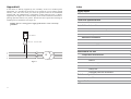
1
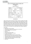
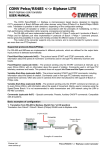
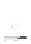
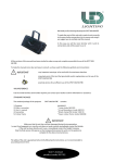
PTC Thermal protection device for electric units 3 ptc input channels, 3 output relays Elettronica Elettronica S.r.l. via Landa, 2/b 40050 Monte San Pietro (BO) Italia tel +39 51 6762544 www.almaelettronica.it 1 5 10 20 40 A1 A2 A3 PTC on USER’S MANUAL Elettronica S.r.l. Appendix A If the device is directly supplied by the secondary circuit of a medium power transformer it is possible for the device to be crushed by a over-voltage of high intensity. This can occur when you insert the general switch of the installation without load. The phenomenon is particularly evident when the PTC is directly supplied by the copper bars of the secondary circuit of the transformer and fixed rephasing capacitor batteries are present. Provide the device protection inserting an insulating 10 VA transformer (see figure 11). Damage due to a wrong power supply of the device is not covered by guarantee. Index Figure Index 4 Introduction 5 Device Overview 5 Technical specifications 6 Cutions 7 Installation Instructions Device and accessories description PTC device 7 Back panel and accessories 8 8 Electrical connections 9 Power Supply 9 Relays outputs connection 9 Probes connection 9 MT 10 Temperature measurement 10 Led 10 Figure 7 14 Frontal panel Instructions for use BT 7 Mechanical installation 220 Vca - 24 Vca 10VA R S T N 7 Buttons 10 Delay setting on channel A1 11 Deactivation of channel A1 11 Relays test 11 Damaged probe test deactivation 11 Solution of problems 12 Guarantee conditions 13 Appendix A 14 3 Solution of problems In this paragraph we give you some suggestions to solve anomalies you can meet using the PTC device. Problem Solution The device does not turn The device turning on is signalled by the lighting of the on led down on the right. Verify the connection to the power supply. Verify there is line voltage. Verify that the power supply values are compliance with those specified in this manual. If the problem persists please contact the device distributor. The device gives no alarm for damaged probe on none of the channels Verify that the damaged probe test has not been deactivated. Verification is done turning on the device: if the horizontal bar leds flash for three times the test has been de-activated. See paragraph Deactivation of damaged probe at page 11. The device gives no alarm for damaged probe on channel A1 Verify that the A1 probe has not been de-activated. The probe is de-activated if no led is turned on the horizontal bar. No delay is visualized on the horizontal bar Push the button with the clock to verify if a led excites: this means the A1 channel was de-activated. If the problem persists please contact the device distributor. Introduction We thank you for your choice to purchase the electronic device for temperature monitoring PTC. This manual explains how to install and use it. For a useful usage of this manual, we suggest you to read it standing near to the PTC device to directly verify the instructions.We suggest indeed to keep the manual for future use. Device Overview The PTC electronic device comes into begin to satisfy the requirements of the insulated resin or dry type transformers users and installers. In details the device characteristics are: ! 3 analog input channels for resistive probes Ptc to measure 3 temperatures with 3 series of probes: A1 series, A2 series and A3 series (figure 1). ! Led to visualize the alarms and the fan deactivation alarms. ! 2 buttons to manage the setup parameters. ! Non volatile data storage of the user's parameters. ! 3 relays output channels to perform three alarm signalling levels on the measured temperatures. The three alarm levels can be used to control the transformer's ventilation, to activate external alarm signalling (as lights and sirens) and to control the protection unhook of the electric unit from the line. The system performs useful setup of delay parameters and an easy activation of the relays test. Transformer column Series A1 Series A2 1 5 10 20 40 A1 Series A3 A2 A3 on PTC Figure 1 12 5 Instructions for use ! Temperature measurement Displaying and data management On the PTC device temperature measurement is done using Ptc probes. These probes change their resistance in a very evidently way when a specific temperature threshold called dNAT is exceeded. Because different constructors provide probes with different characteristics, in the following table the resistance values that generate alarms on the PTC device have been reported. Resistance value R < 15 W 15 W < R < 1800 W 1800 W < R < 200 kW R > 200 kW ! ! ! ! 3 leds indicating alarm levels 1 led indicating working anomalies or probe fault 5 leds to visualize the delay set on A1 series alarm user data programming by membrane keypad Cautions alarms under-range error (short circuit probe) no alarm exceeded threshold alarm over-range error (not connected probe) ! ! ! When the 1800 W value is exceeded the device activates the channel alarm turning on the respective leds and relays. With regard to the probe the device signals errors both for too low (short circuit) and too high resistance (not connected probe). The probe's damage is signalled making the respective channel led flash together with the General Alarm led (A). A1 channel, commonly used for ventilation, provides a delay on the de-activation of the respective relay that keeps on the fan for a programmable time after the temperature is lower than the threshold. When temperature is under the threshold and the A1 relay is still excited because of the delay, the A1 led flashes at a higher frequency than that of the damaged probe flashing. avoid power supply out of the device nominal range use shielded cables for the probes avoid the device working in room with conditions out of the nominal ones previously reported and in particular in presence of condensing humidity. Installation Instructions For a right operation, the PTC device has to be installed compliance to the requirements reported in the Technical Specifications paragraph. The device provides fixing accessories and removable terminals for electrical connections. Device and accessories description Figure 2 represents a scheme of the device. Elettronica The A2 channel relay has an inverse function (see figure 6 and the paragraph Relays output connections) because it is shared in common with the General Alarm (A) that signals a probes' damage or the non function of the device. 1 1 Led Each channel has the respective led on the frontal panel that turns on when the threshold is exceeded. Also a General Alarm (A) led is present that turns on when a probe is damaged. Together with this led, the led of the channel with the damaged probe turns on. There also are 5 leds that visualize in minutes the delay set on the channel A1 alarm (ventilation). The delay times are from 1 to 40 minutes. Alarm signal for working anomalies 5 10 20 2 40 A1 A2 3 A3 Buttons The device has the 2 buttons < and that perform the following functionalities. PTC Delay setting on channel A1 Pushing button it is possible to set the delay for de-activation of the A1 alarm 10 Front view Figure 2 on Frontal Panel 1. Group of 5 leds to visualize the set delay on A1 alarm (ventilation) 2. Button to set the delay on A1 alarm and to deactivate the damaged probe 4 testing 3. Button < to activate the relays testing 4. Led A1, A2, A3 for alrm 5 signalling due to temperature exceeding of the respective probe. 5. G e n e r i c a l a r m l e d f o r 6 malfunctions signalling. This led is on in the following cases: - Malfunctions detected by the self-diagnosis program 7 Notes The ALMA Elettronica S.r.l.company can modify the device and this manual without notice Manual Code M0012 15 Figure index Guarantee conditions Figure 1 Transformer with probes 5 Figure 2 Front view 8 Figure 3 Rear view and accessories 9 Figure 4 Dimensions 10 Figure 5 Electrical connection 10 Figure 6 Relays A2 11 Figure 7 Power supply 12 The thermal protection PTC devices are covered by guarantee for a period of 24 months since the consignment date for anomalies due to production defects. The guarantee consists in the free repair or substitution of the components that have been damaged in the devices' construction, arrived at our office carriage paid. The product's guarantee declines in the following cases: ! device's damages deriving from negligence, use or installation not compliance with the instructions furnished in the user's manual ! wrong power supply ! damages due to changes in the line voltage to which the device is connected as in the case of discharges caused by thunderbolts or other external phenomena ! tampering with the device ! damages due to accidental causes or to negligence ! non-payment of the device The guarantee period is determined on the basis of the serial number written on the device's label so that it has not to be cancelled nor modified. Parts subjected to wear by use are not covered by guarantee. Furthermore, removal and re-installation costs are not covered by guarantee, as transport costs and risks and any other direct or indirect cost due to repair of the device you consider damaged. The constructor declines any responsibility for harms done to persons, animals or things directly or indirectly coming out from a proper or improper use of the device. The device's repair or substitution is subjected to the unobjectionable constructor's opinion. When the guarantee period falls the damaged device's repair will involve the debit entry for the damaged components substitution and for the labour. For any dispute the competent Court is the one of Bologna (Italy). 4 13 Technical specifications Power supply ! ! ! ! ! nominal line voltage and frequency: 24 ÷ 250 Vcc and Vac at 40 ÷ 60 Hz maximum line voltage from 20 to 260 Vcc and Vac Vcc with reversible polarity Maximum power absorption 5 VA Protection against electrical and magnetic noises Inputs ! ! ! ! 3 analog input channels for Ptc probes 2 connection with removable terminals for wires of 1,5 mm section and capacity of 8A/250 Vac detection for broken or not connected probes input channels protected against electromagnetic noises and spikes Outputs ! ! 3 output relays with contacts capacity of 5A with 250Vac - one relay for the series A1 (for fan control) - one ralay for the series A2 (pre-alarm) and for probe fault or working anomaly signaling (general alarm) - one relay for the series A3 (unhook of the electrical unit) 2 output connection with removable terminals for wire of 1,5 mm section and capacity of 8A/250 Vac (ventilation). The delay value is indicated by the 5 led horizontal bar (see point 1 of figure 2 at page 7). The delay values go from 1 to 40 minutes. When the delay is of 40 minutes pushing the button you turn off all the leds of the bar. Pushing the button one more time you restart programming the delay from 1 minute. Deactivation of channel A1 Push the button until all the bar leds are turned off. In this case the channel is deactivated and the device will give no error of not connected probe. Relays test The device provides a procedure called relays test very useful to installers to verify the wiring harness forcing the relays closure. This procedure is activated pushing button < during the turning on of the device. The device normally turns on, then cyclically activates the alarms simulating what would happen if each channel exceeded the temperature threshold. The cycle continues until the button is kept pushed. Damaged probe test deactivation It is possible to de-activate the damaged probe test on all channels keeping pushed the button during the turning on of the device. In this way the device gives no alarm for short circuit or not connected probe. This functionality is signalled during the device switching on making flash three times the horizontal bar leds. Device dimensions ! ! ! ! ! frontal dimension 48 mm x 96 mm compliance with DIN 43700 requirements. Device length of 105 mm with rear terminals assembling on the front of the electric panel Panel cut-out 44 mm x 92 mm ABS self-extinguishing container Frontal panel in anti-scratch poly-carbonate with keyboard and signal leds Performances ! ! ! ! ! ! 6 Probe self-diagnostics Operating temperature range from 5°C to 50°C Humidity lower then 95% no-condensing Compliance with ¯ requirement User data storage for 10 years without power supply Device functionality self-diagnostic 11 Electrical Connections - Damaged or not connected probe 6. Led indicating the operation state of the device All connections are made with the separable clamps provided with the device for an easy wiring harness. Refer to figure 5 and to the clamp numbering. Back view and accessories 1. 2. 3. 4. 5. Power Supply Connector for probes connection Connector for relays output Connector for power supply Removable terminals for wiring harness Clips for the device clamping 1 4 8 1 9 2 Elettronica A3 10 3 4 11 12 13 14 15 A2/ 5 6 7 3 A1 5 2 Rear view and accessories Figure 3 13,43 mm 5 10 20 40 A1 A2 A3 PTC 24,27 mm 92 mm 1 26,32 mm 96 mm mm 44 x 24,03 90,6 mm Elettronica 27,01mm mm 105 The damage due to a wrong power supply is not covered by guarantee. Relays output connections Mechanical Installation The PTC device provides a black self-extinguishing ABS container for the assembly. The device dimensions are compliance to the standard of DIN 43700: 48 x 96 mm section and a maximum depth of 105 mm. The dimensions of the panel perforation are 44 x 92 mm. Assembly is done using c l a m p s provided with the device. See figure 4. mm 9524,54mm The power supply connection is performed connecting the power voltage to the terminals 5 and 7 no matter polarity for Vcc. The nominal allowed voltages are in the 24 Vcc to the 240 Vcc for direct voltage, and in the 24 Vca to the 240 Vca with 50 Hz frequency for the alternate voltage. 5 6 7 The terminal 6 has to be power supply connected to the ground reference. The device has no fusibles inside so it is necessary to provide an 1 2 3 4 8 9 10 11 12 13 14 15 external protection. A1 A2 A3 A3 A2/ A1 The device power supply is input probes Ptc output relays protected from momentary input over-voltages. Figure 5 If the PTC device power supply is directly provided by the secondary circuit of a medium power transformer see Appendix A at the end of the manual. on 48 mm 12,14 mm 44 mm Figure 5 shows the position of the relays when they are not excited (turned off device). The alarm relays are excited when the set limits are exceeded. The alarm relays of the A2 channel and of the General Alarm (A) operate in intrinsic security, so that it is excited at the device switchin on, , and 11 12 13 is de-activated when the conditions that generate one of the 2 alarms occur (figure 6 shows the relay without any alarm). In this way when A2/ the device is turned off you have the non-operating control signalling. Figure 6 Probes Connections The analog inputs are compatible with Ptc resistive probes. Connect the 3 probes series to the device as indicated in figure 5 and place them on the transformer as in figure 1. Figure 4 8 9