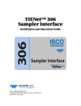
1
Absorbance Absorbance %XPERTS)N-ICROPLATE!NALYSIS %XPERTS)N-ICROPLATE!NALYSIS Plate Washing Plate Washing Luminescence Luminescence 70 75,$'6HULHV0XOWLPRGH'HWHFWRU 75,$'6HULHV0XOWLPRGH'HWHFWRU 70 8VHU¶V0DQXDO 8VHU¶V0DQXDO TRIAD/TRIAD LT Multimode Detectors User’s Manual March 2005 Automated Automated Processing Processing Software Software Consumables Consumables DYNEX Technologies, Inc. DYNEX Technologies, Inc. 14340 Sullyfield Circle, Chantilly, VA 20151-1621 14340 Sullyfield Circle, Chantilly, VA 20151-1621 Phone: (703) 631-7800 FAX: (703) 803-1441 Phone: (703) 631-7800 FAX: (703) 803-1441 www.dynextechnologies.com www.dynextechnologies.com ii Revision History Revision Date: April 2005 Catalog No. 61000064 This manual is published by DYNEX Technologies, Inc. Questions or comments regarding the content of this manual can be directed to the address below or to your supplier. DYNEX Technologies, Inc. 14340 Sullyfield Circle Chantilly, VA 20151-1621 USA Telephone: (800) 288-2354, (703) 631-7800 Fax: (703) 803-1441 Website: www.dynextechnologies.com DYNEX Technologies reserves the right to make technical improvements to this equipment and documentation without prior notice as part of a continuous program of product development. This manual supersedes all previous editions. Microsoft® and Windows® are registered trademarks of the Microsoft Corporation. All other trademarks and registered trademarks are the property of their respective holders. © 2005 Beckman Coulter, Inc. All Rights Reserved. DYNEX Technologies, Inc. iii Warranty and Special Provisions Limited Warranty DYNEX Technologies' products are fully guaranteed for one year against defects in parts, materials, and workmanship. Defective parts and materials will be replaced or, at the discretion of DYNEX Technologies, repaired at no charge for a period of one year and labor required for such replacement or repair will be provided at no charge for a period of one year, provided that the products are utilized and maintained in accordance with the instructions in the applicable operating and servicing manual, and provided further that the products have not, as determined solely by DYNEX Technologies, been subject to misuse or abuse by the Customer or other parties unrelated to DYNEX Technologies. DYNEX Technologies makes no warranty, expressed or implied, as to the fitness of any product for any particular purposes other than those purposes described in the applicable operating and servicing manual, nor does DYNEX Technologies make any other warranty, whether expressed or implied, including merchantability, other than those appearing on the face hereof. Where DYNEX Technologies guarantees any product, whether under this Warranty or as a matter of law, and there is a breach of such guarantee, the Customer's only and exclusive remedy shall be the replacement or repair of defective parts and materials, as described above. This shall be the limit of DYNEX Technologies liability. Furthermore, DYNEX Technologies shall not be liable for incidental or consequential damages. Failure of the Customer to notify DYNEX Technologies of a claimed defect by registered mail within thirty days of the discovery thereof shall constitute a waiver of any claim for breach of warranty. When a product is required by DYNEX Technologies to be installed by a DYNEX Technologies engineer or technician, the period of this Warranty shall begin on the date of such installation, provided, however, that any use of the product prior to such installation shall, at the sole election of DYNEX Technologies, void this Warranty. When installation by DYNEX Technologies personnel is not required, the period of this Warranty shall begin on the date of shipment from DYNEX Technologies. The period of this Warranty shall begin as described above whether or not the product has been installed or shipped pursuant to a purchase order, and any trail period shall be deducted from the Warranty period that would otherwise apply under a subsequent placed purchase order for that product. Limitation of Liability. Notwithstanding anything to the contrary contained herein, the liability of SELLER (whether by reason of breach of warranty, breach of contract, tort, or otherwise), including without limitation under any indemnification provision contained herein, shall be limited to replacement of goods returned to DYNEX Technologies which are shown to DYNEX Technologies’ reasonable satisfaction to have been nonconforming or to refund the purchase price, or, if not paid, to a credit amount of the purchase price therefore. THE FOREGOING WARRANTIES ARE EXCLUSIVE AND ARE GIVEN AND ACCEPTED IN LIEU OF ANY AND ALL OTHER WARRANTIES, EXPRESS OR IMPLIED, INCLUDING WITHOUT LIMITATION, THE IMPLIED WARRANTY OF MECHANTABILITY AND THE IMPLIED WARRANTY OF FITNESS FOR A PARTICULAR PURPOSE. NEITHER PARTY SHALL BE LIABLE TO THE OTHER FOR ANY INCIDENTAL, INDIRECT, SPECIAL, OR CONSEQUENTIAL DAMAGES. TRIAD Series Multimode Detector User’s Manual v Safety Information All Warnings and Cautions in this document include an exclamation point, a lightning bolt, or a light burst symbol framed within a triangle. Please pay special attention to the specific safety information associated with these symbols. WARNING: If the equipment is used in a manner not specified by DYNEX Technologies, Inc., the protection provided by the equipment may be impaired. Warning and Caution Definitions The exclamation point symbol is an international symbol which serves as a reminder that all safety instructions should be read and understood before installation, use, maintenance, and servicing is attempted. When this symbol is displayed in this manual, pay special attention to the specific safety information associated with the symbol. WARNING A WARNING calls attention to a condition or possible situation that could cause injury to the operator. CAUTION A CAUTION calls attention to a condition or possible situation that could damage or destroy the product or the operator’s work. TRIAD Series Multimode Detector User’s Manual vi Electrical Safety To prevent electrically related injuries and property damage, properly inspect all electrical equipment prior to use and immediately report any electrical deficiencies. Contact a DYNEX Technologies service representative for any servicing of equipment requiring the removal of covers or panels. High Voltage This symbol indicates the potential of an electrical shock hazard existing from a high voltage source and that all safety instructions should be read and understood before proceeding with the installation, maintenance, and servicing of all modules. Do not remove system covers. To avoid electrical shock, use supplied power cords only and connect to properly grounded (three-holed) wall outlets. Do not use multiplug power strips. Chemical and Biological Safety Normal operation of the TRIAD LT/TRIAD Multimode Detectors may involve the use of materials that are toxic, flammable, or otherwise biologically harmful. When using such materials, observe the following precautions: • Handle infectious samples according to good laboratory procedures and methods to prevent the spread of disease. • Observe all cautionary information printed on the original solutions containers prior to their use. • Dispose of all waste solutions according to your facility’s waste disposal procedures. • Operate the TRIAD LT/TRIAD Multimode Detectors in accordance with the instructions outlined in this manual, and take all the necessary precautions when using pathological, toxic, or radioactive materials. • Splashing of liquids may occur; therefore, take appropriate safety precautions, such as using safety glasses and wearing protective clothing, when working with potentially hazardous liquids. • Use an appropriately contained environment when using hazardous materials. • Observe the appropriate cautionary procedures as defined by your safety officer when using flammable solvents in or near a powered-up instrument. • Observe the appropriate cautionary procedures as defined by your safety officer when using toxic, pathological, or radioactive materials. Note: Observe all warnings and cautions listed for any external devices attached or used during operation of the TRIAD LT/TRIAD Multimode Detectors. Refer to applicable external device user’s manuals for operating procedures of that device. DYNEX Technologies, Inc. vii Moving Parts To avoid injury due to moving parts, observe the following: • Never attempt to exchange labware, reagents, or tools while the instrument is operating. • Never attempt to physically restrict any of the moving components of the TRIAD LT/TRIAD Multimode Detectors. • Keep the TRIAD LT/TRIAD Multimode Detectors work area clear to prevent obstruction of the movement. Cleaning Observe the cleaning procedures outlined in this user’s manual for the TRIAD LT/ TRIAD Multimode Detectors. Prior to cleaning equipment that has been exposed to hazardous material: • Appropriate Chemical and Biological Safety personnel should be contacted. • The Chemical and Biological Safety information contained in this user’s manual should be reviewed. Maintenance Perform only the maintenance described in this manual. Maintenance other than that specified in this manual should be performed only by DYNEX Technologies Service Engineers. Important It is your responsibility to decontaminate components of the TRIAD LT/TRIAD Multimode Detectors before requesting service by a DYNEX Technologies Service Engineer or returning parts to DYNEX Technologies for repair. DYNEX Technologies will NOT accept any items which have not been decontaminated where it is appropriate to do so. If any parts are returned, they must be enclosed in a sealed plastic bag stating that the contents are safe to handle and are not contaminated. Warnings and Cautions Found in this Manual Please read and observe all cautions and instructions. Remember, the most important key to safety is to operate the TRIAD LT/TRIAD Multimode Detectors with care. The WARNINGs and CAUTIONs found within this document are listed below. WARNING: If the equipment is used in a manner not specified by DYNEX Technologies, Inc., the protection provided by the equipment may be impaired. WARNING: The TRIAD uses a deuterium lamp, which emits UV radiation. Never view the deuterium lamp directly without approved eyewear. Protect skin from exposure to the light emitted by the lamp. TRIAD Series Multimode Detector User’s Manual viii CAUTION: Warranty claims are void if damage during transport is caused by improper packing. CAUTION: The microplate transport may be damaged if the transport lock is not removed before the instrument is powered on. CAUTION: Turn off main power to the instrument before connecting it to the host computer. CAUTION: Handle filter slides by the tab only. Do not touch filter surfaces with fingers. Fingerprints left on filters negatively affect measurement results. CAUTION: Do not touch filter surfaces with fingers. Fingerprints left on filters negatively affect measurement results. CAUTION: Do not overtighten the screw that secures the filter being installed. Overtightening the screw may damage the filter and degrade measurement performance. CAUTION: Filter surfaces are extremely fragile and should be cleaned only when noticeable contamination, such as dust and fingerprints, are visible on the surface. Filters should be cleaned by experienced users only. CAUTION: Use only oil-free compressed air, nitrogen, or canned dusters that do not use freon or similar propellents to blow dust from the filter. Other sources of compressed gas may leave a residue on the filter surface. WARNING: Turn off power and disconnect the instrument from the power source before performing maintenance on the instrument. There is a risk of electric shock when the power is on. WARNING: Never view the deuterium lamp directly without approved eyewear. Protect skin from exposure to the light emitted by the lamp. The lamp emits UV radiation. WARNING: Turn off the instrument and allow a minimum of 30 minutes for the deuterium lamp to cool before servicing. During operation, the lamp reaches a temperature of approximately 250°C (482°F). WARNING: The deuterium lamp may be hot. Handle with caution until it cools. CAUTION: Do not touch the glass of the new lamp. Fingerprints on the glass may shorten the life of the lamp. WARNING: Turn off and unplug power to the instrument before changing fuses. Failure to do so can cause electrical shock or equipment damage. WARNING: Only officially trained DYNEX Technologies Service Engineers may perform service procedures on the instrument. Contact a DYNEX Technologies Service Engineer when service is required. CAUTION: The transport lock must be installed to prevent the possibility of damage to the microplate carrier during transit. DYNEX Technologies, Inc. ix Table of Contents Safety Information . . . . . . . . . . . . . . . . . . . . . . . . . . . . . . . . . . . . . . . . . . v Table of Contents . . . . . . . . . . . . . . . . . . . . . . . . . . . . . . . . . . . . . . . . . . . ix List of Figures . . . . . . . . . . . . . . . . . . . . . . . . . . . . . . . . . . . . . . . . . . . . . . xi 1 Setting Up and Operating the TRIAD LT/TRIAD 1.1 1.2 1.3 Overview . . . . . . . . . . . . . . . . . . . . . . . . . . . . . . . . . . . . . . . . . . . . . . . . . . . . . . . . 1-1 Unpacking and Setting Up the Instrument. . . . . . . . . . . . . . . . . . . . . . . . . . . . . . . 1-3 1.2.1 Unpacking the Instrument. . . . . . . . . . . . . . . . . . . . . . . . . . . . . . . . . . . . 1-3 1.2.2 Setting Up the Instrument . . . . . . . . . . . . . . . . . . . . . . . . . . . . . . . . . . . . 1-5 Preparing the Instrument to Perform Measurements . . . . . . . . . . . . . . . . . . . . . . . 1-7 1.3.1 Starting up the Instrument. . . . . . . . . . . . . . . . . . . . . . . . . . . . . . . . . . . . 1-7 1.3.1.1 Performing an Emergency Stop . . . . . . . . . . . . . . . . . . . . . . 1-8 1.3.2 Exchanging Filter Slides . . . . . . . . . . . . . . . . . . . . . . . . . . . . . . . . . . . . . 1-9 1.3.2.1 Exchanging Excitation Filter Slides . . . . . . . . . . . . . . . . . . 1-10 1.3.2.2 Exchanging Emission Filter Slides . . . . . . . . . . . . . . . . . . . 1-10 1.3.3 Installing, Removing, and Cleaning Filters . . . . . . . . . . . . . . . . . . . . . 1-11 1.3.3.1 Installing and Removing Excitation and Emission Filters . 1-11 1.3.3.2 Cleaning Excitation and Emission Filters. . . . . . . . . . . . . . 1-13 1.3.3.3 Installing and Removing Polarization Filters (TRIAD only) . . . . . . . . . . . . . . . . . . . . . . . . . . . . . . . . 1-14 1.3.4 Selecting Microplate Types Suitable for Measurements . . . . . . . . . . . 1-15 1.3.5 Loading and Unloading Microplates . . . . . . . . . . . . . . . . . . . . . . . . . . 1-16 2 Performing Basic Maintenance and Troubleshooting 2.1 2.2 2.3 2.4 2.5 2.6 Overview . . . . . . . . . . . . . . . . . . . . . . . . . . . . . . . . . . . . . . . . . . . . . . . . . . . . . . . . Performing Preventive Maintenance . . . . . . . . . . . . . . . . . . . . . . . . . . . . . . . . . . . Replacing the Deuterium Lamp (TRIAD only) . . . . . . . . . . . . . . . . . . . . . . . . . . . Replacing Fuses . . . . . . . . . . . . . . . . . . . . . . . . . . . . . . . . . . . . . . . . . . . . . . . . . . . Troubleshooting . . . . . . . . . . . . . . . . . . . . . . . . . . . . . . . . . . . . . . . . . . . . . . . . . . . Repacking the Instrument for Storage and Shipment . . . . . . . . . . . . . . . . . . . . . . 2-1 2-2 2-3 2-5 2-6 2-7 TRIAD Series Multimode Detector User’s Manual x A Appendix A: Specifications A.1 A.2 Instrument and System Specifications . . . . . . . . . . . . . . . . . . . . . . . . . . . . . . . . . . A-1 Measurement Specifications . . . . . . . . . . . . . . . . . . . . . . . . . . . . . . . . . . . . . . . . . A-3 Index. . . . . . . . . . . . . . . . . . . . . . . . . . . . . . . . . . . . . . . . . . . . . . . . . . . . . xiii DYNEX Technologies, Inc. xi List of Figures Figure 1-1. The TRIAD LT/TRIAD Multimode Detector .......................................................... 1-1 Figure 1-2. Instrument with transport lock in place..................................................................... 1-4 Figure 1-3. Power switch and connection ports........................................................................... 1-5 Figure 1-4. Installing filter slides................................................................................................. 1-6 Figure 1-5. Instrument status LEDs ............................................................................................. 1-7 Figure 1-6. Performing an emergency stop ................................................................................. 1-8 Figure 1-7. Changing filter slides ................................................................................................ 1-9 Figure 1-8. Changing individual filters...................................................................................... 1-11 Figure 1-9. Installing a polarization filter .................................................................................. 1-14 Figure 1-10. Load/eject button................................................................................................... 1-16 Figure 1-11. Microplate carrier with plate in landscape orientation.......................................... 1-17 Figure 2-1. Replacing the deuterium lamp .................................................................................. 2-4 Figure 2-2. Fuse carrier location.................................................................................................. 2-5 Figure 2-3. Transport lock ........................................................................................................... 2-8 TRIAD Series Multimode Detector User’s Manual 1-1 1 1.1 Setting Up and Operating the TRIAD LT/TRIAD Overview The TRIAD LT and TRIAD are computer-controlled multimode detectors capable of performing absorbance, luminescence, and fluorescence intensity measurements on microplate samples (Figure 1-1). Control buttons and status LEDs Deuterium lamp housing cover (TRIAD only) Filter compartment Microplate carrier Figure 1-1. The TRIAD LT/TRIAD Multimode Detector TRIAD Series Multimode Detector User’s Manual 1-2 Setting Up and Operating the TRIAD LT/TRIAD The TRIAD LT provides the ability to perform: • absorbance measurements at wavelengths between 340 and 650 nm. • glow type luminescence measurements at wavelengths between 400 and 650 nm. • fluorescence intensity measurements (top reading) at wavelengths between 340 and 650 nm. • measurements on samples in 96- and 384-well microplates. • linear, orbital, and squared microplate shaking. WARNING: The TRIAD uses a deuterium lamp, which emits UV radiation. Never view the deuterium lamp directly without approved eyewear. Protect skin from exposure to the light emitted by the lamp. The TRIAD provides the same abilities as the TRIAD LT, and adds: • a deuterium light source, which extends sensitivity into the deep UV band. • absorbance measurements at wavelengths between 230 and 650 nm. • glow type luminescence measurements at wavelengths between 400 and 750 nm. • fluorescence intensity measurements (top reading) at wavelengths between 230 and 750 nm. • fluorescence intensity measurements (bottom reading) at wavelengths between 300 and 650 nm. • time-resolved fluorescence (TRF) measurements at wavelengths between 340 and 750 nm. • fluorescence polarization (FP) measurements at wavelengths between 300 and 750 nm. • measurements on samples in 6-, 12-, 24-, and 48-well microplates. • temperature control in the microplate chamber during measurements. The TRIAD LT and TRIAD are operated remotely via a host computer using the supplied Concert - TRIAD Series Software. The software configures and performs all measurement types supported by the instruments, provides the ability to control instrument operations manually, and displays and saves measurement results. Setting up and operating the TRIAD LT or TRIAD includes: DYNEX Technologies, Inc. • Unpacking and Setting Up the Instrument (Section 1.2). • Preparing the Instrument to Perform Measurements (Section 1.3). Setting Up and Operating the TRIAD LT/TRIAD 1.2 1-3 Unpacking and Setting Up the Instrument Place the instrument on any dry, flat work area that has sufficient space for the instrument, host computer, and required cables. Setting up the instrument includes: • Unpacking the instrument, removing the transport lock, and saving the original packaging (refer to Section 1.2.1, Unpacking the Instrument). • Physically setting up the instrument, connecting it to the host computer, and installing Concert - TRIAD Series Software (refer to Section 1.2.2, Setting Up the Instrument). 1.2.1 Unpacking the Instrument The packaging is specifically designed to protect the instrument during transportation. A transport lock protects the microplate carrier and transport by preventing movement during transit. The lock must be removed before turning on power to the instrument. Removing the transport lock requires a 2.0 mm Allen wrench, which is provided with the instrument. CAUTION: Warranty claims are void if damage during transport is caused by improper packing. To unpack the instrument: 1. Check the box for any visible damage during transportation. In case of damage, inform the supplier immediately and keep the damaged packing. 2. Open the box lid and remove the accessories box. 3. Carefully lift the instrument out of the box by the molded foam packaging encasing it. 4. Gently place the instrument on a dry, flat area. 5. Remove the molded foam packaging from the instrument and place it back in the shipping box. 6. Remove the plastic surrounding the instrument and discard. TRIAD Series Multimode Detector User’s Manual 1-4 Setting Up and Operating the TRIAD LT/TRIAD CAUTION: The microplate transport may be damaged if the transport lock is not removed before the instrument is powered on. 7. Gently pull the plastic tab protruding from the microplate chamber door. The door opens, revealing the transport lock that fastens the microplate carrier to the internal frame of the instrument (Figure 1-2). The microplate carrier door must be held open manually while removing the transport lock. Screw #1 Fastens the lock to the internal frame of the instrument Transport lock Screws #2 and #3 Fasten the lock to the microplate carrier Microplate carrier Microplate chamber door (open) Figure 1-2. Instrument with transport lock in place 8. Using the 2.0 mm Allen wrench, loosen screw #1 in the upper left corner of the transport lock until the lock disconnects from the instrument frame (Figure 1-2). The screw is equipped with a retaining washer that prevents it from being removed from the lock. 9. Loosen screws #2 and #3 until the lock comes free of the carrier (Figure 1-2). The screws are equipped with retaining washers that prevent them from being removed from the lock. 10. Gently close the microplate chamber door. 11. Save the original carton, foam inserts, accessories box, and transport lock in case the instrument must be shipped in the future. DYNEX Technologies, Inc. Setting Up and Operating the TRIAD LT/TRIAD 1.2.2 1-5 Setting Up the Instrument Setting up the instrument includes selecting a suitable work area, installing excitation and emission filter slides, connecting the host computer, and installing Concert TRIAD Series Software, which controls all actions performed by the instrument. To set up the instrument: 1. Place the instrument and host computer on a dry, flat work area with sufficient space for both devices and the required cables. To ensure adequate ventilation, a 20 – 30 cm (7.9 – 11.8 in) gap should be left between the back of the instrument and wall. 2. Connect one end of the 9-pin serial cable to the serial port on the computer. Note: Only use the original serial cable supplied with the instrument. Other serial cables with identical connectors may not establish communication between the instrument and computer. CAUTION: Turn off main power to the instrument before connecting it to the host computer. 3. Connect the other end of the 9-pin serial cable to the serial port on the back of the instrument (Figure 1-3). Serial port Power switch Power port Figure 1-3. Power switch and connection ports 4. Connect the power cable to the power port on the back of the instrument (Figure 1-3) and to the wall socket. 5. Turn on the power switch on the back of the instrument (Figure 1-3). The instrument performs an initialization procedure that moves the optics and microplate transports to home positions. TRIAD Series Multimode Detector User’s Manual 1-6 Setting Up and Operating the TRIAD LT/TRIAD 6. Remove the excitation filter slide from the toolbox supplied with the instrument. Excitation filter slides are identified by the EX or EXP printed on the slide tab. ¾ TRIAD — Slides labeled EXP may also house polarization filters, and are designed for use with this instrument only. 7. Open the filter compartment door on the front of the instrument. 8. Holding the excitation filter slide by the tab, orient it vertically, with the gear teeth on top, facing to the left of the instrument (Figure 1-4). Excitation filter slide Emission filter slide Figure 1-4. Installing filter slides 9. Align the slide in the track, and gently push it into the filter compartment until the motor automatically retracts it into position. 10. Remove the emission filter slide from the toolbox supplied with the instrument. Emission filter slides are identified by the EM or EMP printed on the slide tab. ¾ TRIAD — Slides labeled EMP may also house polarization filters, and are designed for use with this instrument only. 11. Open the filter compartment door on the front of the instrument. 12. Holding the emission filter slide by the tab, orient it horizontally, with the gear teeth on the right, facing up (Figure 1-4). 13. Align the slide in the track, and gently push it into the filter compartment until the motor automatically retracts it into position. 14. Turn on power to the host computer. 15. Install Concert - TRIAD Series Software on the computer (refer to the Concert TRIAD Series Software User’s Manual, Section 1.3, Installing Concert - TRIAD Series Software). 16. From the Start menu, choose Programs>Dynex Technologies>Concert TRIAD Series>Concert - TRIAD Series. The software launches and initializes the instrument transports. 17. In Concert - TRIAD Series Software, configure the communications and software settings (refer to the Concert - TRIAD Series Software User’s Manual, Section 1.4, Setting Up Concert - TRIAD Series Software). DYNEX Technologies, Inc. Setting Up and Operating the TRIAD LT/TRIAD 1.3 1-7 Preparing the Instrument to Perform Measurements Preparing the TRIAD LT/TRIAD to perform measurements includes: • Starting up the Instrument (Section 1.3.1). • Exchanging Filter Slides (Section 1.3.2). • Selecting Microplate Types Suitable for Measurements (Section 1.3.4). • Loading and Unloading Microplates (Section 1.3.5). 1.3.1 Starting up the Instrument After turning on the power switch at the rear of the instrument, two LEDs on the front panel indicate the current status of the instrument (Figure 1-5): • Continuous green — the instrument is ready for operation. • Continuous green and amber — the instrument is busy; wait until the amber LED turns off before attempting to perform operations. OR Instrument operations are halted by an emergency stop; cancel the emergency stop to continue (refer to Section 1.3.1.1, Performing an Emergency Stop). • Flashing green — a problem occurred during initialization; the instrument is not ready for operation. • Not illuminated — the instrument is not ready for operation. Green LED Amber LED Figure 1-5. Instrument status LEDs Each time the instrument is turned on or Concert - TRIAD Series Software is launched, an initialization procedure automatically moves the optics and microplate transports to home positions. For optimal performance, allow the instrument to warm up for 30 minutes before performing measurements. ¾ TRIAD — When temperature control for the microplate chamber is set, reaching the desired temperature may take longer than 30 minutes. TRIAD Series Multimode Detector User’s Manual 1-8 Setting Up and Operating the TRIAD LT/TRIAD 1.3.1.1 Performing an Emergency Stop If necessary, any instrument operation may be stopped immediately by performing an emergency stop. During an emergency stop, the instrument firmware is disabled, which prevents any further operations from being performed until the emergency stop is cancelled. To perform an emergency stop: 1. On the front panel of the instrument, press EX FILTER and EM FILTER simultaneously (Figure 1-6). Both LEDs turn on and remain lit for the duration of the emergency stop. LEDs Press simultaneously Figure 1-6. Performing an emergency stop 2. If a filter slide unloads from the filter compartment, gently push it into the instrument until it is automatically retracted back into position. To cancel an emergency stop: 1. Turn the instrument off and on again. The instrument automatically initializes the plate and optics transports when the instrument is turned on. OR On the front panel of the instrument, press EX FILTER and EM FILTER simultaneously (Figure 1-6). 2. In Concert - TRIAD Series Software, initialize the instrument (refer to the Concert - TRIAD Series Software User’s Manual, Section 2.2.3, Initializing the Instrument). DYNEX Technologies, Inc. Setting Up and Operating the TRIAD LT/TRIAD 1.3.2 1-9 Exchanging Filter Slides Filters used in measurements are mounted on two interchangeable slides, which are easily accessed from the front panel of the instrument (Figure 1-7). One slide is reserved for excitation filters used in absorbance and fluorescence measurements; the other for emission filters used in fluorescence and some luminescence measurements. Slides may be quickly exchanged at any time between measurements. When a slide is exchanged, an identification code built into the slide allows Concert - TRIAD Series Software to recognize the new slide and filter configuration. Up to 31 excitation and 31 emission slide configurations may be saved in the software at one time. Slides hold up to six filters, and may be reconfigured as desired. Individual filters may be installed in, removed from, or moved to a different location on the same or different slide. Refer to Section 1.3.3, Installing, Removing, and Cleaning Filters, for detailed information about changing the filters installed on a slide. This section covers: • Exchanging Excitation Filter Slides (Section 1.3.2.1). • Exchanging Emission Filter Slides (Section 1.3.2.2). Filter compartment door EX FILTER button EM FILTER button Excitation filter slide Emission filter slide Figure 1-7. Changing filter slides TRIAD Series Multimode Detector User’s Manual 1-10 Setting Up and Operating the TRIAD LT/TRIAD 1.3.2.1 Exchanging Excitation Filter Slides Excitation filters are used in absorbance and fluorescence measurements to pass only the wavelength of light required for excitation. The excitation filter slide is oriented vertically on the left side of the filter compartment (Figure 1-7). Excitation filter slides are identified by the EX or EXP printed on the slide tab. Slides labeled EXP may also house polarization filters, and are designed for use with the TRIAD. To exchange excitation filter slides: 1. On the front panel of the instrument, press EX FILTER. The slide unloads from the filter compartment and partially opens the compartment door. CAUTION: Handle filter slides by the tab only. Do not touch filter surfaces with fingers. Fingerprints left on filters negatively affect measurement results. 2. Open the compartment door all the way, grasp the slide by the tab, and pull it until it is free of the geared track. 3. Store the slide in a protected, dust-free area, preferably in the supplied toolbox. 4. Holding the new slide by the tab, orient it vertically, with the gear teeth on top, facing to the left of the instrument (Figure 1-7). 5. Align the slide in the track, and gently push it into the filter compartment until the motor automatically retracts it into position. 6. Close the compartment door completely to ensure the accuracy of measurements. 7. In Concert - TRIAD Series Software, update or create the slide configuration, if necessary (refer to the Concert - TRIAD Series Software User’s Manual, Section 2.3.2, Defining and Editing Filter Slides). Note: The slide configuration needs to be modified only if the slide is not recognized by the software or if the filters installed on the slide have changed. 1.3.2.2 Exchanging Emission Filter Slides Emission filters are used in fluorescence measurements to separate fluorescence generated by the sample from background light. The emission filter slide is oriented horizontally near the top of the filter compartment (Figure 1-7). Emission filter slides are identified by the EM or EMP printed on the slide tab. Slides labeled EMP may also house polarization filters, and are designed for use with the TRIAD. To exchange emission filter slides: 1. On the front panel of the instrument, press EM FILTER. The slide unloads from the filter compartment and partially opens the compartment door. CAUTION: Handle filter slides by the tab only. Do not touch filter surfaces with fingers. Fingerprints left on filters negatively affect measurement results. 2. Open the compartment door all the way, grasp the slide by the tab, and pull it until it is free of the geared track. 3. Store the slide in a protected, dust-free area, preferably in the supplied toolbox. 4. Holding the new slide by the tab, orient it horizontally, with the gear teeth on the right, facing up (Figure 1-7). DYNEX Technologies, Inc. Setting Up and Operating the TRIAD LT/TRIAD 1-11 5. Align the slide in the track, and gently push it into the filter compartment until the motor automatically retracts it into position. 6. Close the compartment door completely to ensure the accuracy of measurements. 7. In Concert - TRIAD Series Software, update or create the slide configuration, if necessary (refer to the Concert - TRIAD Series Software User’s Manual, Section 2.3.2, Defining and Editing Filter Slides). Note: The slide configuration needs to be modified only if the slide is not recognized by the software or if the filters installed on the slide have changed. 1.3.3 Installing, Removing, and Cleaning Filters Individual filters may be installed in, removed from, or moved to a different location on the same or different filter slide. This section covers: • Installing and Removing Excitation and Emission Filters (Section 1.3.3.1). • Cleaning Excitation and Emission Filters (Section 1.3.3.2). • Installing and Removing Polarization Filters (TRIAD only) (Section 1.3.3.3). 1.3.3.1 Installing and Removing Excitation and Emission Filters Excitation and emission filters drop into one of the slots on the slide, and are secured by a 1.5 mm hex screw. A 1.5 mm Allen wrench is provided with the instrument. To change an excitation or emission filter: 1. Using the provided 1.5 mm Allen wrench or a hex driver, loosen, but do not remove, the screw securing the filter to the filter slide (Figure 1-8). Polarization filter (TRIAD only) Filter slot 1 Excitation or emission filter Filter Slide 1.5 mm hex screw Filter slot 6 Figure 1-8. Changing individual filters TRIAD Series Multimode Detector User’s Manual 1-12 Setting Up and Operating the TRIAD LT/TRIAD CAUTION: Do not touch filter surfaces with fingers. Fingerprints left on filters negatively affect measurement results. 2. Grasp the filter by the edges and gently pull it free of the slot. ¾ TRIAD — If removing a filter from a slot housing a polarization filter, use tweezers to gently slide the polarization filter out far enough to allow the removal of the excitation or emission filter. Completely removing the polarization filter from the slide is not recommended (refer to Section 1.3.3.3, Installing and Removing Polarization Filters (TRIAD only)). 3. Store the filter in protective, dust-free packaging, preferably the original packaging supplied with the filter. Filters should be stored in a low humidity environment. Note: Filters may be cleaned when noticeable contamination, such as dust and fingerprints, are visible on the filter surface (refer to Section 1.3.3.2, Cleaning Excitation and Emission Filters). 4. Holding the new filter by the edges, gently place it in the desired slot. Excitation and emission filters are different sizes to prevent them from being installed on the wrong type of filter slide (refer to Table 1-1 for dimensions). Note: Some excitation filters have a heat reflecting coating on one side which must face the light source. An arrow printed on the filter ring indicates the correct direction of light flow through the filter. To install this type of filter, hold the excitation filter slide so that it is oriented correctly for installation in the instrument — vertically, with the gear teeth on top, facing to the left of the instrument. Place the filter in the desired slot with the arrow pointing from left to right. ¾ TRIAD — If installing a filter in a slot housing a polarization filter, use tweezers to slide the polarization filter back into position over the filter (refer to Section 1.3.3.3, Installing and Removing Polarization Filters (TRIAD only)). Table 1-1. Minimum and Maximum Filter Dimensions Filter Type Diameter Minimum Maximum Thickness Minimum Maximum Excitation 12.2 mm (.49 in) 12.7 mm (.50 in) 6 mm (.24 in) 9 mm (.35 in)* Emission 17.7 mm (.70 in) 18 mm (.71 in) 9 mm (.35 in)* 5 mm (.20 in) * On a filter slide for a TRIAD detector, filters up to 10 mm (.39 in) thick may be used in slots where no polarization filter is housed. CAUTION: Do not overtighten the screw that secures the filter being installed. Overtightening the screw may damage the filter and degrade measurement performance. 5. Use the provided 1.5 mm Allen wrench or a hex screwdriver to gently tighten the screw until the filter is secured. DYNEX Technologies, Inc. Setting Up and Operating the TRIAD LT/TRIAD 1-13 6. When a new filter changes the slide configuration, take note of: • The wavelength and type of filter. Both are generally printed on the filter. • The slot where the filter is installed. The slot closest to the slider tab is slot 1; the slot furthest away is slot 6 (Figure 1-8). • The filter slide identification number printed on the slide. This information must be edited in the slide definition before using the slide in measurements (refer to the Concert - TRIAD Series Software User’s Manual, Section 2.3.2, Defining and Editing Filter Slides). 1.3.3.2 Cleaning Excitation and Emission Filters Excitation and emission filters may be cleaned; however, to minimize the risk of damaging the surface, filters should be cleaned only when the surface is noticeably dirty. Follow the guidelines in this section to safely and effectively clean filters. CAUTION: Filter surfaces are extremely fragile and should be cleaned only when noticeable contamination, such as dust and fingerprints, are visible on the surface. Filters should be cleaned by experienced users only. To clean filters: 1. Place a soft, clean cloth on the work surface to protect the filter in case it is accidentally dropped during cleaning. 2. Wear powder-free latex gloves or finger cots to reduce the risk of damaging the filter surface and to protect skin from cleaning solvents. CAUTION: Use only oil-free compressed air, nitrogen, or canned dusters that do not use freon or similar propellents to blow dust from the filter. Other sources of compressed gas may leave a residue on the filter surface. 3. Remove dust by blowing air from a canned duster or bulb-type blower over the filter surface. Bulb blowers must be periodically cleaned to prevent contaminating the surface. OR Gently wipe dust from the filter surface with a camel hair brush. The brush must be periodically cleaned to prevent contaminating the filter surface. 4. Examine the filter surface. If no contamination remains, return the filter to the filter slide or packaging; no further cleaning is necessary. If contamination, such as fingerprints, is still present on the surface, continue with step 5. 5. If contamination remains, apply a drop of spectroscopic grade isopropyl alcohol on an unused cotton swab and gently sweep the filter surface from edge to edge in a single direction only. This prevents debris from being dragged across the surface multiple times. 6. Examine the filter surface. If contamination remains, repeat step 5. TRIAD Series Multimode Detector User’s Manual 1-14 Setting Up and Operating the TRIAD LT/TRIAD 1.3.3.3 Installing and Removing Polarization Filters (TRIAD only) Acetate polarization filters used in fluorescence polarization measurements slide into place over the desired excitation and emission filters. Acetate filters are fragile and must be handled with care using tweezers. It is recommended that polarization filters only be changed by experienced users. To help ensure that polarization filters are installed with the polarization axes oriented correctly, filter positions on the slide are grouped in pairs. The positions in a pair have different height and width dimensions. Only a polarization filter with the same dimensions as the desired position may be installed in that position. This prevents two filters with the same polarization axis from being installed next to each other. To install or remove a polarization filter: CAUTION: Do not touch filter surfaces with fingers. Fingerprints left on filters negatively affect measurement results. 1. Handling the polarization filter with tweezers, match the dimensions of the filter with the corresponding filter position on the filter slide. 2. To install a filter, gently slide the filter into the guide slots over the filter until it is securely in place (Figure 1-9). OR To remove a filter, using tweezers, gently pull the filter free of the guide slots (Figure 1-9). Polarization filter (TRIAD only) Filter Slide Figure 1-9. Installing a polarization filter 3. If removing a filter, immediately place the filter in the protective packaging supplied with the filter. DYNEX Technologies, Inc. Setting Up and Operating the TRIAD LT/TRIAD 1.3.4 1-15 Selecting Microplate Types Suitable for Measurements The type of microplate and the way it is handled can affect the measurement performance of the instrument. Plate height may not exceed 25 mm. Select a plate type with properties suited for the application and for use with multimode detectors. Table 1-2 lists microplate selection guidelines for each supported measurement type. Plate handling guidelines include: • Never touch the bottom of plates. Visually inspect the bottom of the plate before use to make sure it is free of dirt and contaminants. • Keep unused plates clean and dry. • Make sure the strips on strip plates are inserted correctly and level with the frame. • Do not use V-bottom plates, unless performance has been tested and verified with this instrument. Irregular plastic density in the tip of the well may cause inaccurate measurements. Table 1-2. Microplate selection guidelines Measurement Technique Microplate Type Additional Considerations Fluorescence Intensity (Top Reading) solid black When an application specifies a surface treatment, only use plates with the correct treatment. Fluorescence Intensity (Bottom Reading) black with clear bottom When an application specifies a surface treatment, only use plates with the correct treatment. Fluorescence Polarization solid black When an application specifies a surface treatment, only use plates with the correct treatment. Time-Resolved Fluorescence solid white When an application specifies a surface treatment, only use plates with the correct treatment. Luminescence Glow Type solid black or solid white Black plates are recommended unless the signal is weak enough to require the higher sensitivity of white plates. However, with strong signals, white plates may produce crosstalk. When an application specifies a surface treatment, only use plates with the correct treatment. Absorbance clear, white with clear bottom, or black with clear bottom Clear polystyrene or film plates with transparent bottoms are suitable. Polypropylene or PVC plates do not provide sufficient optical quality. When an application specifies a surface treatment, only use plates with the correct treatment. TRIAD Series Multimode Detector User’s Manual 1-16 Setting Up and Operating the TRIAD LT/TRIAD 1.3.5 Loading and Unloading Microplates The load/eject button on the front panel of the instrument allows microplates to easily be loaded and unloaded from the instrument. Plates may be loaded into the instrument in either portrait or landscape orientation. To load or unload a microplate: 1. On the front panel of the instrument, press the load/eject button (Figure 1-10). The plate carrier moves outside the instrument. Load/eject button Figure 1-10. Load/eject button 2. Remove the microplate from or place it on the microplate carrier. Microplates may be placed on the plate carrier in either landscape or portrait orientation. Note: In landscape orientation, well A1 is placed in the back left corner (Figure 1-11). In portrait orientation, well A1 is placed in the back right corner. If desired, opposite landscape and portrait orientations may be specified when protocols are run (refer to the Concert - TRIAD Series Software User’s Manual, Section 6.3.1, Running a Protocol on an Instrument). DYNEX Technologies, Inc. Setting Up and Operating the TRIAD LT/TRIAD 1-17 Load/eject button Well A1 Landscape orientation Figure 1-11. Microplate carrier with plate in landscape orientation 3. Press the load/eject button (Figure 1-10). The plate carrier moves inside the instrument. TRIAD Series Multimode Detector User’s Manual 2-1 2 2.1 Performing Basic Maintenance and Troubleshooting Overview Several maintenance procedures may be performed by users to ensure the optimum operation of the instrument, including: • Performing Preventive Maintenance (Section 2.2). • Replacing the Deuterium Lamp (TRIAD only) (Section 2.3). • Replacing Fuses (Section 2.4). • Troubleshooting (Section 2.5). • Repacking the Instrument for Storage and Shipment (Section 2.6). TRIAD Series Multimode Detector User’s Manual 2-2 2.2 Performing Basic Maintenance and Troubleshooting Performing Preventive Maintenance To ensure optimum operation of the instrument, perform the following preventive maintenance procedures as necessary: DYNEX Technologies, Inc. • Wipe up any spills immediately. • Follow appropriate decontamination procedures as instructed by the laboratory safety officer. • Contact a DYNEX Technologies Service Engineer to inspect the instrument every two years. • Use a DYNEX Technologies verification plate to regularly verify the performance of the instrument. Contact a DYNEX Technologies salesperson or service engineer for more details. • Respond appropriately to any error messages displayed by Concert - TRIAD Series Software. Refer to the Concert - TRIAD Series Software User’s Manual, Appendix C, Appendix C: Software Error Codes, for more information. Performing Basic Maintenance and Troubleshooting 2.3 2-3 Replacing the Deuterium Lamp (TRIAD only) The TRIAD is equipped with a deuterium lamp, which is used in measurements made at wavelengths between 230 and 359 nm. The lamp needs to be replaced when Concert - TRIAD Series Software warns that lamp energy is too low to perform measurements. Replacing the deuterium lamp requires a 2 mm Allen wrench and a 2.5 x 0.6mm flathead screwdriver. The Allen wrench is provided with the instrument; the screwdriver with the replacement deuterium lamp. To replace the deuterium lamp: WARNING: Turn off power and disconnect the instrument from the power source before performing maintenance on the instrument. There is a risk of electric shock when the power is on. WARNING: Never view the deuterium lamp directly without approved eyewear. Protect skin from exposure to the light emitted by the lamp. The lamp emits UV radiation. WARNING: Turn off the instrument and allow a minimum of 30 minutes for the deuterium lamp to cool before servicing. During operation, the lamp reaches a temperature of approximately 250°C (482°F). 1. Turn off power and disconnect the power cable from the instrument. 2. On the top of the instrument case, use the supplied 2 mm Allen wrench to remove the two Allen screws that secure the lamp housing cover (Figure 2-1). The lamp and power connector are now accessible. 3. On the lamp power cable connector, press down on the locking clip to unlatch the connector. With the clip unlatched, disconnect the lamp power cable from the instrument. 4. Loosen, but do not attempt to completely remove, the two flathead captive screws that secure the deuterium lamp. Captive screws are designed to remain connected to the lamp base. TRIAD Series Multimode Detector User’s Manual 2-4 Performing Basic Maintenance and Troubleshooting Lamp housing cover Allen screws Lamp power cable and connector Alignment notch Flathead captive screws Deuterium lamp Figure 2-1. Replacing the deuterium lamp WARNING: The deuterium lamp may be hot. Handle with caution until it cools. 5. Once cooled, remove the deuterium lamp and discard. CAUTION: Do not touch the glass of the new lamp. Fingerprints on the glass may shorten the life of the lamp. 6. Taking care not to touch the glass bulb with bare hands, line up the alignment notch in the base of the lamp with the guide on the lamp block to position the new lamp correctly. 7. Tighten the two flathead captive screws to secure the new deuterium lamp. 8. Reconnect the lamp power cable, making sure the locking clip on the connector is latched. Note: The lamp power cable connector is keyed, which prevents it from being connected incorrectly. 9. Replace the lamp housing cover and tighten the two Allen screws that secure it in place. 10. Reconnect the power cable to the instrument, and turn on power to the instrument. DYNEX Technologies, Inc. Performing Basic Maintenance and Troubleshooting 2.4 2-5 Replacing Fuses If the instrument will not power on or shuts down due to a power loss, or if the fuses appear burned, replace them. Fuses are located in the fuse carrier on the back of the instrument next to the power switch and power port (Figure 2-2). Power switch Fuse carrier Power port Figure 2-2. Fuse carrier location To replace the fuses: WARNING: Turn off and unplug power to the instrument before changing fuses. Failure to do so can cause electrical shock or equipment damage. 1. Turn off the main power to the instrument. 2. Unplug the power cord from the power port. 3. Using a small flathead screwdriver, gently pry the fuse carrier loose and remove it from the instrument. 4. Gently pull old fuses from the carrier by hand. 5. Gently place new fuses into carrier by hand. Note: Use 250v 3 amp slow-blow type fuses for replacement. 6. Replace the fuse carrier. 7. Plug the power cable into the power port. 8. Turn on power to the instrument. Note: If the instrument still does not power on after changing fuses, contact a DYNEX Technologies Service Engineer. TRIAD Series Multimode Detector User’s Manual 2-6 2.5 Performing Basic Maintenance and Troubleshooting Troubleshooting WARNING: Only officially trained DYNEX Technologies Service Engineers may perform service procedures on the instrument. Contact a DYNEX Technologies Service Engineer when service is required. Perform the following troubleshooting techniques when necessary. Table 2-1. Troubleshooting the TRIAD LT/TRIAD If Then The green power indicator LED is out Check fuses. Power is on, but the instrument does not operate Check fuses. The fuses appear burned or filaments are broken Replace fuses (refer to Section 2.4, Replacing Fuses). The green power indicator LED is Contact a DYNEX Technologies Service out, the power on, the fuses okay, Engineer. and the instrument does not operate The instrument does not respond to Check the serial cable connections to the commands instrument and host computer. In Concert - TRIAD Series Software, verify that the serial port configured matches the serial port connecting the instrument to the computer (refer to the Concert - TRIAD Series Software User’s Manual, Section 2.2.4, Connecting to the Instrument). If the green and amber LEDs on the front panel are both on: • The instrument is busy. Wait until the amber LED turns off before performing an operation. OR • DYNEX Technologies, Inc. An emergency stop was performed. On the front panel of the instrument, press EX FILTER and EM FILTER simultaneously to cancel the emergency stop (refer to Section 1.3.1.1, Performing an Emergency Stop). Performing Basic Maintenance and Troubleshooting 2.6 2-7 Repacking the Instrument for Storage and Shipment To minimize the possibility of damage during storage or shipment, the instrument should be repacked only in the original packaging materials. Correctly repacking the instrument includes following appropriate decontamination procedures and installing the transport lock on the microplate carrier. The instrument should be stored in a dry, dust-free, environmentally controlled area. Refer to Table A-1 for more information about acceptable storage environments. To repack the instrument: CAUTION: Warranty claims are void if damage during transport is caused by improper packing. 1. Follow appropriate decontamination procedures as instructed by the laboratory safety officer. 2. On the front panel of the instrument, press EX FILTER. The excitation filter slide unloads from the filter compartment and partially opens the compartment door. CAUTION: Handle filter slides by the tab only. Do not touch filter surfaces with fingers. Fingerprints left on filters negatively affect measurement results. 3. Open the compartment door all the way, grasp the slide by the tab, and pull it until it is free of the geared track. 4. Place the excitation filter slide in the toolbox supplied with the instrument. 5. On the front panel of the instrument, press EM FILTER. The emission filter slide unloads from the filter compartment and partially opens the compartment door. 6. Open the compartment door all the way, grasp the slide by the tab, and pull it until it is free of the geared track. 7. Place the emission filter slide in the toolbox supplied with the instrument. 8. On the instrument control panel, press the load/eject button to move the microplate carrier outside of the instrument. 9. Turn off power to the instrument. 10. Disconnect the power cable from the wall socket and power port on the back of the instrument. CAUTION: The transport lock must be installed to prevent the possibility of damage to the microplate carrier during transit. 11. Using the provided 2 mm Allen wrench, tighten transport lock screws #2 and #3 until the lock is fastened to the microplate carrier (Figure 2-3). TRIAD Series Multimode Detector User’s Manual 2-8 Performing Basic Maintenance and Troubleshooting Screw #1 Fastens the lock to the internal frame of the instrument Transport lock Screws #2 and #3 Fasten the lock to the microplate carrier Microplate carrier Microplate chamber door (open) Figure 2-3. Transport lock 12. When the transport lock is securely fastened to the microplate carrier, gently push the carrier to the left of the microplate chamber until it stops. Next, push it straight back into the instrument until screw #1, which fastens the lock to the internal frame of the instrument, is lined up with the hole on the internal frame. The microplate chamber door must be held open manually until the transport lock is fastened. 13. Tighten screw #1 until the microplate carrier is securely locked in place. 14. Route the plastic tab connected to the transport lock so that it will pass over the top of the microplate chamber door when closed. 15. Gently close the microplate chamber door. 16. Disconnect the serial cable from the serial ports on the host computer and instrument. 17. Put the power and serial cables into the accessories box. 18. Wrap the instrument in static-free plastic. 19. Replace the molded foam packaging around the instrument. 20. Place the instrument and accessories box in the original shipping box. 21. Close the box using packing tape. DYNEX Technologies, Inc. A-1 A Appendix A: Specifications A.1 Instrument and System Specifications Table A-1. Instrument Specifications Item Description Environment Indoor use only Power Requirements 100 – 240VAC ±10% frequency range: 50/60Hz Dimensions 39 cm (15.4 in) W x 24 cm (9.5 in) H x 58 cm (22.9 in) L Weight 25 kg (55.1 lbs) Ambient Operating Temperature 15 – 40°C (59 – 104°F) Ambient Storage Temperature -5 – 40°C (23 – 104°F) continuous; -20 – 50°C (-4 – 122°F) transient (up to 10 hours) Humidity Restrictions 15 – 75% (non-condensing) @ 30°C (86°F) Altitude Restrictions up to 2000 m (6,562 ft) Air Pressure Restrictions 54 – 106 kPa (7.8 – 15.4 PSI) Sound Pressure Level Maximum sound pressure: 75 dBA Maximum sound pressure at one meter: 68 dBA Installation Category II Pollution Degree 2 Fuses 250V, 3 amp, 5x20 mm, slow-blow, UL recognized/CSA/VDE Data Connection RS-232 9-pin serial TRIAD Series Multimode Detector User’s Manual A-2 Appendix A: Specifications Table A-2. Temperature Control Specifications (TRIAD only) Item Description Temperature Range 3°C (5.4°F) above ambient – 45°C (113°F) (VIS; > 359 nm) 4°C (7.2°F) above ambient – 45°C (113°F) (UV; deuterium lamp) Displayed 1°C (1.8°F) increments Accuracy +/- 1°C (1.8°F) Uniformity 1.5°C (2.7°F) Table A-3. Concert - TRIAD Series Software Computer System Requirements Component DYNEX Technologies, Inc. Minimum Requirements CPU Pentium® II 300 Mhz RAM 128 MB minimum 256 MB recommended Hard Drive 300 MB free space CD-ROM Drive 4X Monitor 800x600 resolution Keyboard 101 key Mouse IBM® compatible Serial Port 1 free serial port Operating Systems Windows NT® 4 (Service Pack 6a) Windows® 2000 (Service Pack 1) Windows® XP (Service Pack 1) Operating System Language English (U.S.) Web Browser Internet Explorer 6.0 or later Appendix A: Specifications A.2 A-3 Measurement Specifications Table A-4. Absorbance Specifications Parameter Specification Measurement Method Transmission Photometer Light Source TRIAD LT: High Power LEDs TRIAD: High Power LEDs and Deuterium Lamp Detector Silicon Photodiode Wavelength Range TRIAD LT: 340 – 650 nm TRIAD: 230 – 650 nm Filter Slide Positions 6 Supplied Wavelengths TRIAD LT: 405, 450, 492, 620 nm TRIAD: 260, 340, 405, 450, 595, 620 nm (additional filters are available ) Resolution 0.1 mOD from 0 – 3.5 OD Measurement Range 0 – 3.0 OD (> 399 nm, specified) 0 – 2.5 OD (< 400 nm, specified) Indication Range 0 – 3.5 OD Accuracy <±1% and ± 10 mOD at 2.0 OD (at 405 nm) Linearity <±0.75% and ±0.010 OD from 0.1 – 3.0 OD (>399 nm) <±0.75% and ±0.010 OD from 0.1 – 2.5 OD (< 400 nm) Reproducibility <±0.5% and ±0.005 OD at 2.0 OD (400 – 650 nm) <±0.5% and ±0.005 OD at 1.0 OD (230 – 399 nm) Measurement Modes single, dual, and multiple wavelength; scan; kinetic Shaking orbital, linear, and squared: 3 speeds TRIAD Series Multimode Detector User’s Manual A-4 Appendix A: Specifications Table A-5. Fluorescence Intensity Top Specifications Parameter Specification Light Source TRIAD LT: High Power LEDs TRIAD: High Power LEDs and Deuterium Lamp Detector Photo Multiplier; Single Photon Counting Wavelength Range TRIAD LT: Excitation: 340 – 630 nm; Emission 390 – 650 nm TRIAD: Excitation: 230 – 650 nm; Emission 390 – 750 nm Filter Slide Positions 6 Supplied Wavelengths TRIAD LT: Excitation: 360, 485 nm; Emission: 465, 535, 625 nm TRIAD: Excitation: 485, 535 nm; Emission: 535, 595, 625 nm Detection Limit TRIAD LT: 10 fmol/200 µL fluorescein, black 96-well plate; 1 second integration time 5 fmol/100 µL fluorescein, black 384-well plate; 400 ms integration time TRIAD: 1.5 fmol/200 µL fluorescein, black 96-well plate; 1 second integration time 1.5 fmol/100 µL fluorescein, black 384-well plate; 400 ms integration time Linear Dynamic Range 5 decades Integration Time/Well 10 – 10,000 ms Table A-6. Fluorescence Intensity Bottom Specifications (TRIAD only) Parameter Specification Light Source High Power LEDs and Deuterium Lamp Detector Photo Multiplier; Single Photon Counting Wavelength Range Excitation: 300 – 630 nm; Emission 390 – 650 nm Filter Slide Positions 6 Supplied Wavelengths Excitation: 485, 535 nm Emission: 535, 595, 625 nm Detection Limit 50 fmol/200 µL fluorescein, black 96-well plate; 1 second integration time 25 fmol/100 µL fluorescein, black 384-well plate; 400 ms integration time Integration Time/Well 10 – 10,000 ms DYNEX Technologies, Inc. Appendix A: Specifications A-5 Table A-7. Luminescence Specifications Parameter Specification Detector Photo Multiplier; Single Photon Counting Wavelength Range TRIAD LT: 400 – 650 nm TRIAD: 400 – 750 nm Detection Limit 2 fmol ATP; white 96-well plate Linear Dynamic Range 5 decades Integration Time/Well 10 – 10,000 ms Table A-8. Fluorescence Polarization Specifications (TRIAD only) Parameter Specification Light Source High Power LEDs and Deuterium Lamp Detector Photo Multiplier; Single Photon Counting Wavelength Range Excitation: 300 – 650 nm; Emission 390 – 750 nm Filter Slide Positions 6 Supplied Wavelengths Excitation: 485 nm Emission: 535 nm Detection Limit 5 mP at 10 nM fluorescein, black 96-well plate; 1 second integration time 5 mP at 10 nM fluorescein, black 384-well plate; 400 ms integration time Integration Time/Well 10 – 10,000 ms TRIAD Series Multimode Detector User’s Manual A-6 Appendix A: Specifications Table A-9. Time-Resolved Fluorescence Specifications (TRIAD only) Parameter Specification Light Source High Power LEDs Detector Photo Multiplier; Single Photon Counting Wavelength Range 340 – 750 nm Filter Slide Positions 6 Supplied Wavelengths Excitation: 370 nm; Emission 625 nm Note: TRF measurements can only be performed with the 370 nm broadband filter supplied by DYNEX Technologies. Use of this filter is required to achieve the specified performance. Detection Limit 50 amol/200 µL Europium, white 96-well plate; 1 second integration time 30 amol/100 µL Europium, white 384-well plate; 400 ms integration time Linear Dynamic Range 5 decades Number of Pulses/Well 100 – 1,000,000 DYNEX Technologies, Inc. xiii Index D deuterium lamp replacing 2-3 E emission filters cleaning 1-13 exchanging 1-10 minimum and maximum dimensions 1-12 excitation filters cleaning 1-13 exchanging 1-10 minimum and maximum dimensions 1-12 F filter slides exchanging excitation filters 1-10 installing and removing filters 1-11 overview 1-9 filters cleaning 1-13 exchanging emission 1-10 exchanging excitation 1-10 installing and removing individual 1-11 installing and removing polarization 1-14 fuses replacing 2-5 I instrument overview 1-1 preventive maintenance 2-2 repacking 2-7 replacing fuses 2-5 replacing lamp 2-3 setting up 1-5 starting up 1-7 troubleshooting 2-6 unpacking 1-3 P plates loading and ejecting 1-16 selecting suitable types for measurements 1-15 polarization filters changing and removing 1-14 preventive maintenance 2-2 R repacking instrument 2-7 replacing fuses 2-5 S setting up instrument 1-5 starting up instrument 1-7 T transport lock installing 2-7 removing 1-4 troubleshooting instrument 2-6 U unpacking instrument 1-3 TRIAD Series Multimode Detector User’s Manual