1
M - 622
Operation manual
Precision Resistance Decade
M-622 Precision Resistance Decade
MEATEST
Content
1.
USE OF THE INSTRUMENT .................................................................................................................... 4
2.
CONTENTS OF DELIVERY ..................................................................................................................... 4
3.
TECHNICAL DATA ................................................................................................................................... 4
4.
PREPARATION FOR USE ........................................................................................................................ 7
4.1.
4.2.
5.
SWITCHING ON ...................................................................................................................................... 7
WARM-UP TIME ..................................................................................................................................... 7
DESCRIPTION ............................................................................................................................................ 7
5.1.
5.2.
6.
FRONT PANEL ........................................................................................................................................ 7
REAR PANEL .......................................................................................................................................... 9
OPERATION ............................................................................................................................................... 9
6.1.
6.2.
6.3.
6.4.
SWITCH ON AND OFF .............................................................................................................................. 9
STANDARD MODE ................................................................................................................................ 10
SETUP MODE ....................................................................................................................................... 10
CALIBRATION MODE ............................................................................................................................ 13
7.
PERFORMANCE VERIFICATION TEST ............................................................................................ 16
8.
REMOTE CONTROL............................................................................................................................... 18
8.1.
8.2.
8.3.
8.4.
8.5.
COMMANDS......................................................................................................................................... 18
COMMAND LIST ................................................................................................................................... 18
REMOTE CONTROL RS232 ................................................................................................................... 21
REMOTE CONTROL IEEE488 (OPTIONALY) .......................................................................................... 21
DEMO PROGRAM ................................................................................................................................. 22
9.
MODULE 19” (EXTRA ORDERED OPTION)...................................................................................... 23
10.
ELECTRIC FUNCTION........................................................................................................................... 23
11.
MECHANICAL CONSTRUCTION ........................................................................................................ 23
11.1.
11.2.
BATTERY MAINTENANCE ..................................................................................................................... 23
BATTERY REPLACEMENT ..................................................................................................................... 24
ORDERING INFORMATION – OPTIONS ........................................................................................... 24
12.
3
Version 23
Operation manual
MEATEST
1.
M - 622 Precision Resistance Decade
Use of the instrument
Resistance decade M-622 is precise programmable resistance decade in range 1.000 00 Ohm to
1 200 000 Ohm. It is designed for checking of parameters of resistance meters and regulators and
process meters, which use external resistance sensors for non-electric quantity measuring. Set
resistance value is created via appropriate combination of physical resistors. Decade is equipped with
build-in function of direct simulation of most frequent temperature Pt and Ni sensors. Low thermal
voltage relays and stable foil resistors with low temperature coefficient are used as main parts of the
decade. Actual set values are displayed on the front panel display. Resistance decade is supplied from
internal battery. External power line adapter is delivered as power line source and as internal battery
charger in one. M-622 is sophisticated instrument with its own re-calibration procedure. The
procedure enables to correct any deviation in resistance without any mechanical adjusting.
Instrument is especially suitable for automatic testing procedures. RS232 line (optionally
IEEE488 bus) is used for connecting decade to the computer.
2.
Contents of delivery
RS232 version
IEEE488 version
Resistance decade M622-V1xxx
Power line adapter
Cable RS-232
Demo program
User’s manual
Test report
Resistance decade M622-V2xxx
Power line adapter
Demo program
User’s manual
Test report
3. Technical data
Only values, functions, ranges with signed accuracy in relative or absolute expression or where
limits are specified, are guaranteed.
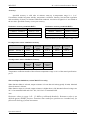
Resistance range
:
Pt sensor temperature simulation
Ni sensor temperature simulation
Type of temperature sensors
Resolution
:
:
:
:
Operation manual
1.000 00 - 1 200 000
SHORT, OPEN terminals
(version M622-Vx1xx only)
-200.000 C … 850.000 C (-328 F … 1562 F)
-60.000 C … 300.000 C (-76 F … 572 F)
Pt10 … Pt20000, Ni10 … Ni20000
0.000 01 for 1.000 00 … 10.000 00
0.000 1 for 10.0001 … 100.000 0
0.001 for 100.001 … 400.000
0.01 for 400.01 … 1 200.00
0.1 for 1200.1 … 30 000.0
1 for 30000 … 1 200 000
0.001 C for Pt10 … Pt300, Ni10 … Ni300
4
M-622 Precision Resistance Decade
Pt temperature standards
MEATEST
:
Ni temperature standards
:
Resistance temperature coefficient :
Maximal dissipation power
Maximal voltage
:
:
Connection of output terminals
Connection of temperature sensors
Reaction time *
Terminals
Interface
Power supply
:
:
:
:
:
:
Operating period from battery
Reference temperature
Working temperature
Storing temperature
Housing
Dimensions (table version)
Dimensions (19” module)
Weight
:
:
:
:
:
:
:
:
0.01 C for Pt301 … Pt10000, Ni301 … Ni10000
IEC 751 (1,3850 for IPTS68)
IEC 751 (1,3851 for ITS90)
US (US/JIS) (1,3916)
DIN 43760 (6180)
< 1 ppm/ C (1 - 2000 ) on terminals R4W
< 1 ppm/ C (100 - 1200 k) on terminals R2W
< 5 ppm/ C (2 k - 10 k) on terminals R4W
0,3 W
50 V DC, 50 Vef AC on terminals R4W
120 V DC, 50 Vef AC on terminals R2W
2, 4 wire
2, 3 or 4 wire
6 ms
instrument terminals diameter 4mm, gold plated
RS232 as standard (IEEE488 optionally)
internal battery 12 V type LONG B-WP 1.9-12
power line adapter 15VDC/2A 100 – 240 V
6 hours
+18 C … +28 C
+5 C … +40 C
-10 C … +50 C
ALU
W 364 mm, H 111 mm, D 316 mm (without holder)
W 483 mm, H 133 mm, D 316 mm
4.5 kg
Isolation resistance between output terminals and housing :
> 2 G (at 500V DC)
* Reaction time means time interval between setting up value from front panel or receiving command from remote control
bus and settling set-up value on output terminals.
Notes:
Only data shown with tolerance or with band of limits are tested. All other values have
informative character.
During over-switching, resistance circuit may be opened for a period about 1 ms.
5
Operation manual
MEATEST
M - 622 Precision Resistance Decade
Accuracy
Specified accuracy is valid after 10 minutes warm up in temperature range 23 ± 5 oC.
Uncertainties include long-term stability, temperature coefficient, linearity, load and line regulation
and traceability of factory to National calibration standards. Accuracies assigned in % are related to
the set value. Specified accuracy is one-year accuracy.
Resistance accuracy (terminals R4W)
Resistance accuracy (terminals R2W)
Range
Accuracy
Range
Accuracy
1.00000 - 400.000
0.003 % + 3 m
1.00000 - 2000.0
0.005 % + 10 m
400.01 - 2000.0
0.005 %
2000.1 k - 200.000 k
0.005 %
2000.1 - 10000.0
0.015 %
200.001 k - 1200.000 k
0.01 %
Maximal thermoelectric voltage on terminals R4W is 1 V.
Maximal thermoelectric voltage on terminals R2W in resistance
range 1 to 2 k is 5 V and in range 2 k to 1.2 M is 15 V.
Pt temperature sensor simulation accuracy
Temperature range
Pt100
(terminals
R4W)
Pt200
(terminals
R4W)
Pt500
(terminals
R4W)
Pt1000
(terminals
R4W)
Pt10000
(terminals
R2W)
-200.000 … 200.000 C
0.02 C
0.02 C
0.02 C
0.04 C
0.04 C
200.001 … 500.000 C
0.03 C
0.04 C
0.06 C
0.1 C
0.06 C
500.001 … 850.000 C
0.04 C
0.06 C
0.15 C
0.2 C
0.1 C
Ni temperature sensor simulation accuracy
Temperature range
Ni100
(terminals
R4W)
Ni1000
(terminals
R4W)
Ni10000
(terminals
R2W)
-60.000 … 300.000 C
0.02 C
0.04 C
0.04 C
Temperature coefficient outside of the reference temperature range is 10 % of the stated specification
per °C.
Short and Open simulation (version M622-Vx1xx only)
When function Short is selected, output resistance is lower than 100 m (typically 50 m). Maximal
allowed current is 500 mA.
When function Open is selected, output resistance is higher than 1 G. Maximal allowed voltages are
50 V ef on terminals R4W and 120 V DC, 50 Vef AC on terminals R2W.
Note:
Resistance values in range 1 - 1.2 M are calibrated absolutely. Resistance value is not
defined against SHORT position. Functions Short and Open positions are intended only for
functional checking of tested instrument.
Operation manual
6
M-622 Precision Resistance Decade
MEATEST
4. Preparation for use
M-622 Resistance decade is supplied from internal battery or from external power line adapter.
Range of power line voltage is from 100 V to 240 V 50/60 Hz. M-622 is laboratory device. Its
accuracy is guaranteed in temperature range 23 5 C. Instrument is aimed for use in horizontal or
slope position. The angle of slope is determined by downcast holder.
After unpacking put the instrument on flat desk. If the instrument was stored out of range of
reference temperatures, let it stabilize for one hour.
4.1.
Switching on
If the instrument is supplied from internal battery only, push the button POWER. If power line
adapter is connected, decade will switch on automatically. After switching on internal tests are
performed for approx. 3s. On the display type name of the instrument and manufacturer are displayed
during internal test. After finishing, setting to the position before last switching off is performed.
Factory setting is resistance mode, value 100.
4.2.
Warm-up time
Decade can operate immediately after switching on. After 10 min. warm-up period it meets
specified accuracy. During warm-up period it is not recommended to perform recalibration.
5. Description
5.1.
Front panel
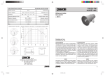
On the front panel there are located all main control keys, display and output terminals.
Keyboard
Numerical values can be entered from the numerical part of keyboard. Keys with number 2, 4, 6, 8
have also next meaning as display cursor keys. Except numerical there are following keys in the
keyboard:
7
Operation manual
MEATEST
Key
MENU
BSP
ESC
ENTER
POWER
M - 622 Precision Resistance Decade
Meaning
enters to the SETUP/CALIBRATION MENU.
deletes last entered number.
cancels last entered value or leaves last set mode
confirms set value or confirms selected item in MENU or switches between numerical
function (black label) and display cursor function (blue label) of the keys 2, 4, 6, 8.
Switching over is indicated with symbol ( ) in right low corner of the display.
switches on and off the decade. When switching off is requested, two-times the key must
be pushed to confirm switching off.
Display
Two-row alphanumerical display is used for displaying all information. Main value, i.e. simulated
temperature or output resistance is displayed in upper row. Auxiliary information is displayed in
lower row. Depending on status following symbols can be displayed in right low corner:
keys 2, 4, 6 and 8 are switched to the cursor function (blue labels are valid)
decade is in remote control via RS232 (IEEE488 optionally)
internal battery is out of power
power line adapter is connected
Output terminals
Output resistance is available on either R4W or on R2W output terminals. Upper four terminals
R4W enable 2 and 4 wire connection of resistance decade and 2, 3 and 4 wire connection, if decade is
used as Pt/Ni temperature sensor simulator. Resistance range on these terminals is from 1 to
maximal R = 10 k. Upper limit R depends on setting of parameter 4W < 2W. Lower line of
terminals with label R2W can be used for two-wire connection only. Total resistance range on these
terminals is from R = 1 to 1.2 M. Value of lower limit R depends on setting of parameter 4W <
2W.
Decade automatically switches between R2W and R4W output terminals according to
resistance value. Low resistance values are connected always to R4W terminals. Resistance value,
where over-switching from R4W terminals to R2W terminals is performed can be set in MENU,
parameter 4W < 2W. Range of this point setting covers values from 0 to 10 k and can be set with
1 resolution. Resistance of preset 4W < 2W value is always available still on R4W terminals. When
4W < 2W value is set to 0 , R2W terminals are used as output only. Recommended 4W < 2W value
is 2000 .
Active terminals are indicated with lighting LED diode on front panel.
Left terminal with symbol “GROUND” is connected with the housing.
Operation manual
8
M-622 Precision Resistance Decade
5.2.
MEATEST
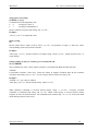
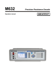
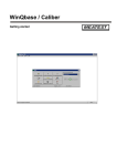
Rear panel
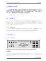
RS232 interface
Power line adapter
IEEE488
interface
Power line adapter
On the rear panel there are located power supply connector, interface RS-232 connector
(optionally IEEE488 connector) and serial number plate.
6. Operation
6.1.
Switch on and off
When supplied from power line adapter, decade is automatically switched on all this time the
adapter is connected to the power source.
When supplied from internal battery (power line adapter is not connected to the power line
connector, or adapter is not connected to the power source), decade must be switched on by pushing
the key POWER. To switch off the decade, push the same key two times. When supplied from
internal battery, decade is automatically switch off, if for last 20 minutes no one key was pushed or if
internal battery is discharged. One minute before automatic switching off, decade displays symbol
and beeps to warn the user.
9
Operation manual
MEATEST
6.2.
M - 622 Precision Resistance Decade
Standard mode
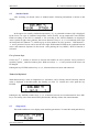
After switching on decade comes to standard mode. Following information is shown on the
display:
In the upper row actually simulated temperature [C] or generated resistance [] is displayed.
In the lower row type of simulated temperature sensor (Pt100), set-up temperature scale IPTS68,
ITS90 according to the IEC751 standard or US according to the US/JIS standards are displayed.
Arrow symbol in right corner informs, that cursor function of keys 2, 4, 6, 8 is initialized (blue signs
on front panel foil). Buttons enable step up or down number on active position . With buttons
active position of cursor can be moved left or right. With button ENTER can be switched between
cursor and numerical keyboard in this mode. After pushing the key MENU, SETUP function is
activated.
Use of cursor keys
Cursor keys enables to increase or decrease the number on active position. Active position is
signed by symbol _ under the number place. With cursor keys active position of the cursor can
be changed.
Pushing the key ENTER switches keys 2, 4, 6, 8 function between cursor and numerical.
Numerical keyboard
With numerical keys value of temperature (or resistance) can be directly entered. Recently entered
value is displayed in brackets under the actually set value. To confirm new value push the key
ENTER.
Pushing the key ENTER switches keys 2, 4, 6, 8 function between cursor and numerical. Press ESC
key to exit setting value from numerical keyboard mode. BSP key deletes last entered number.
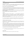
6.3.
Setup mode
This mode enables to set or display some auxiliary parameters. To enter this mode push the key
Operation manual
10
M-622 Precision Resistance Decade
MEATEST
MENU in standard mode. To leave setup mode push the key ESC. With cursor keys following
items in setup menu can be displayed:
Function
With buttons following functions can be set-up:
R
- resistance function. Total range of resistance is 1.00000 to 1200000 .
Pt (68)
- simulation of Pt temperature sensors according to standard IEC 751 (temperature scale
IPTS68, coefficient 1,3850). Range of setting -200 C to 850 C (-328 F to 1562 F).
Parameter R0 (resistance at 0C) can be set-up in range 10 to 20 000 .
Pt (90)
- simulation of Pt temperature sensors according to standard IEC 751 (temperature scale
ITS90, coefficient 1,3851). Range of setting -200 C to 850 C (-328 F to 1562 F).
Parameter R0 (resistance at 0C) can be set-up in range 10 to 20 000 .
Pt (US)
- simulation of Pt temperature sensors according to standard US/JIS (temperature scale
ITS90, coefficient 1,3851). Range of setting -200 C to 850 C (-328 F to 1562 F).
Parameter R0 (resistance at 0C) can be set-up in range 10 to 20 000 .
Ni
- simulation of Ni temperature sensors according to standard DIN 43760 (coefficient
6180). Range of setting -60 C to 300 C (-76 F až 572 F). Parameter R0 (resistance at
0C) can be set-up in range 10 to 20 000 .
User
- by user defined temperature function. As default, NTC thermistor sensor with
temperaure function
R(T) = 330*exp (-4050*((1/298,15)-(1/(T+273,15))))
is delivered. Range of simulation is -30 C to 110 C.
This function can be changed in MEATEST Company only (extra ordered option).
Please specify in your order.
Short
- simulates short on the output terminals. Function Short is extra ordered option.
Open
- simulates open on the output terminals. Function Open is extra ordered option.
Items from MENU are displayed on lower row. After selecting an item and pressing the button
ENTER, symbol of this new selected temperature/resistance function is written to upper row. Selected
function is valid even if the instrument is switched off and on again (except of Short and Open
functions).
R0 (Pt,Ni) (resistance at 0C)
The function enables to set-up parameter R0 for temperature sensors. Set value R0 is valid for both Pt
and Ni sensors. New value can be written after changing keyboard meaning to numerical by pushing
ENTER. Allowed range is from 10 to 20 000 . To confirm new value press ENTER. New value is
valid even if the instrument is switched off and on again.
4W < 2W (the highest resistance value on R4W terminals)
The function enables to pre-set resistance value, where instrument automatically switches active
output terminals from R4W to R2W and back. Resistance values higher than 10 000 are available
only on terminals R2W. Lower values than 10 000 can be available either on R2W terminals – but
with a little bit worse accuracy or on R4W terminals with the lowest uncertainty. Resistance point,
where decade swiches between both terminals can be modificated here. New value can be written
after changing keyboard meaning to numerical by pushing ENTER. Allowed range is from 10 to 10
000 . To confirm new value press ENTER. New value is valid even if the instrument is switched off
and on again.
11
Operation manual
MEATEST
M - 622 Precision Resistance Decade
T. unit (temperature unit)
With buttons either C or F can be set-up here. Possibilities are shown in lower row. After
selecting one of them and pressing the button ENTER appropriate symbol is written to upper row.
New value is valid even if the instrument is switched off and on again.
Baud rate RS-232 (optionally IEEE488 address)
In standard version, the function involves to set parameter baud rate of RS-232 interface. With keys
any value from the row 300, 600, 1200, 2400, 4800, 9600 or 19200 Bd can be set. Set baud rate
is displayed in lower row. To change currently valid value to the new value press the key ENTER.
The newly set baud rate is written into the upper row.
If the decade is optionally equipped with IEEE488, instead of “Baud rate” you can set IEEE488
address of instruments.
In decade with IEEE488 interface, IEEE488 address can be set-up here. The address range is 0 to 30.
The last set baud rate is valid even if the instrument is switched off.
Lighting
Enables or disables lighting of the display. With keys values OFF (lighting is switched off), 30
s (lighting is switched on for 30 s after last key pressing), 5m (lighting is switched on for 5
minutes after last key pressing) or ON (lighting is switched on) can be set. Selected parameter is
displayed in lower row. To change currently selected parameter press the key ENTER. The newly set
parameter is written into the upper row.
If the instrument is supplied from the external power adapter, lighting is switched on permanently.
Note: Display lighting influences significantly operating period from the internal battery. If not used
when instrument is supplied from internal battery, the working period can be lengthen about 50%.
Calibration mode password setting
Calibration password is a five-digit number, which must be entered to access the calibration mode. If
the password is set to “00000”, this information is displayed in the Setup menu, otherwise only
symbols “*****” are shown.
Password can be changed. New password can be entered directly from keyboard after changing
keyboard meaning to numerical by pushing ENTER. If previous password was “00000”, simply type
new 5-digit code and press ENTER. New password is saved and cannot be read in MENU. If previous
password was non-zero, new password can be entered in two steps. In the first step original password
must be entered and confirmed by pressing ENTER. If it is correct symbols “00000” are displayed.
Now new password can be entered and saved according to above described procedure.
New password is valid even if the instrument is switched off and on again.
Note: it is advisable to write down actual password if changed. If you forget the calibration code, you
have to send the decade to the manufacturer.
Serial number
Displays the serial number of the decade. The parameter cannot be changed.
Operation manual
12
M-622 Precision Resistance Decade
6.4.
MEATEST
Calibration mode
In this mode resistance elements of the decade can be recalibrated. Access to the calibration
mode is enabled after double pushing the key MENU from the standard mode or after single pushing
the same key from the SETUP mode.
Correct password must be entered before calibration. Without correct password the access to
the calibration mode is refused. Default factory set calibration code is “00000”. Return to standard
mode is possible after pushing the key ESC.
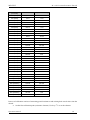
Recalibration procedure consists of measuring of 36 basic resistance values and entering their
actually measured data. Among calibration values can be moved with keys .
In following table nominal values of calibration points and requested recalibration accuracy are
described:
13
Operation manual
MEATEST
M - 622 Precision Resistance Decade
Standard
(terminals)
R00 (R4W)
Nominal value
Requested Accuracy
2,0
1 m
R01 (R4W)
3,9
1 m
R02 (R4W)
7,8
1 m
R03 (R4W)
15,4
1 m
R04 (R4W)
30,5
1 m
R05 (R4W)
60,5
1 m
R06 (R4W)
120
2 m
R07 (R4W)
237
3 m
R08 (R4W)
464
6 m
R09 (R4W)
909
15 m
R10 (R4W)
1780
30 m
R11 (R4W)
3480
100 m
R12 (R4W)
6870
250 m
R13 (R4W)
13,5 k
500 m
R14 (R4W)
26,6 k
1
R15 (R4W)
52,2 k
5
R16 (R4W)
103 k
10
R17 (R4W)
202 k
20
R18 (R4W)
398 k
40
R19 (R4W)
780 k
80
R20 (R4W)
1540 k
200
R21 (R4W)
3020 k
400
R22 (R4W)
5920 k
1 k
R23 (R4W)
12 M
5 k
R24 (R4W)
23 M
50 k
R25 (R4W)
48 M
200 k
R26 (R4W)
100 M
500 k
R27 (R2W4W)
1780
40 m
R28 (R2W4W)
3830
80 m
R29 (R2W4W)
7870
100 m
R30 (R2W4W)
15,8 k
200 m
R31 (R2W4W)
34 k
500 m
R32 (R2W4W)
75 k
1
R33 (R2W4W)
150 k
4
R34 (R2W4W)
301 k
10
R35 (R2W4W)
602 k
20
Process of calibration consists of measuring partial resistances and writting their actual values into the
decade:
Set the first calibration point (resistance element). Use keys to set the element.
Operation manual
14
M-622 Precision Resistance Decade
MEATEST
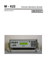
Measure resistance of the selected element. Use ohm-meter with appropriate accuracy in 4wire connection and with appropriate accuracy.
Change function of the keyboard to the numerical one by pushing the key ENTER.
Write measured resistance value (there is original value in the first row and newly entered
value in the second row). Newly entered value must to be written down in units Ohm.
Confirm new calibration data by pushing the key ENTER.
Repeat above described procedure for all resistance elements.
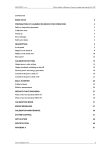
Recommended connection of standard ohm-meter for calibration points R00 to R26 (terminals R4W) :
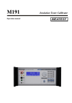
Recommended connection of standard ohm-meter for calibration points R27 to R35 (terminals R2W) :
15
Operation manual
MEATEST
M - 622 Precision Resistance Decade
7. Performance verification test
Parameter verification procedure is described in the chapter. Verification procedure is based on
measuring resistance on the decade output terminals with standard multimeter in recommended
points.
Required equippment
Ohm-meter nominal accuracy 0.001% in range 1 to 1.2 M (type Wavetek 1281 or similar)
Decade setting
Switch decade to the resistance function. Connect standard multimeter to the decade output terminals.
Use four-wire connection technique.
Range of the test
output resistance on terminals R4W checking
output resistance on terminals R2W checking
Procedure
Use following procedure to perform parameter verification test.
1. Switch both instruments on and let them for 1 hour stabilise in the laboratory with ambient
temperature 232 oC. Connect resistance decade terminals R4W to the standard ohm-meter
(multimeter). Set value 4W<2W to 10 kOhm in SETUP menu.
2. Check resistance value in points according to Table I.
I. Maximal deviations on terminals R4W
Nominal value []
1.00000
2.00000
5.00000
10.00000
20.0000
50.000
100.000
200.00
500.00
1000.0
2000.0
5000.0
10000.0
Max. deviation [m]
3.03
3.06
3.15
3.3
3.6
4.5
6.0
9.0
25
50
100
750
1500
3. Connect standard ohm-meter to R2W terminals on resistance decade. Use four-wire connection to
10 kOhm. Above this point both two-wire and four-wire connection can be used. Set function
4W<2W to 0 in SETUP menu.
4. Check resistance value in points according to Table II.
Operation manual
16
M-622 Precision Resistance Decade
MEATEST
II. Maximal deviations on R2W terminals
Nominal value []
1.00000
10.00000
100.000
1000.0
2000.0
5000.0
10000.0
20000.0
50000
100000
200000
500000
1000000
1200000
17
Max. deviation []
0.01
0.011
0.015
0.060
0.1
0.25
0.5
1.0
2.5
5.0
20
50
100
120
Operation manual
MEATEST
M - 622 Precision Resistance Decade
8. Remote control
Standard version is equipped with RS232 bus. IEEE488 version is described in chapter 8.4.
Commands for both versions are the same.
8.1.
Commands
Communication between decade and computer consists of flow of periodically alternating
commands type command-response or query-response. Command is always a letter followed by
parameter and ended by control sign <cr> or <lf>. Response is always ended with control signs <cr>
<lf>.
Syntax description
<DNPD> = Decimal Numeric Program Data, this format is used to express decimal number with or
without the exponent.
<CPD> = Character Program Data. Usually, it represents a group of alternative character
parameters. E.g. {0 | 1 | 2 | 3}.
?=
A flag indicating a request for the value of the parameter specified by the command. No
other parameter than the question mark can be used.
(?) =
A flag indicating a request for the parameter specified by the command. This command
permits a value to be set as well as requested.
<cr> =
carriage return. ASCII code 13. This code executes the program line.
<lf> =
line feed. ASCII code 10. This code executes the program line.
8.2.
Command list
Value setting / reading
A (?) <DNPD>
The command sets resistance value (resistance function) or temperature value (temperature sensor
simulating function).
<DNPD>
It represents resistance value in Ohm or simulated temperature in oC. When temperature parameter is
used, both negative and positive values are acceptable. For resistance parameter positive value only is
acceptable. Limit values are shown in chapter “Technical data”.
In case of control, the decade confirms correct setting with string „Ok <cr><lf>”.
In case of query, M-622 returns set resistance/temperature value in the same format as it is on the
display (number of decimal places). For example value -120 C is returned as -120.000<cr><lf>.
Positive numbers are sent without polarity sign.
Example :
Command „A123.564 <cr>” sets temperature 123.564 C if decade is in temperature simulation
function and 123.564 if decade is in resistance function.
Operation manual
18
M-622 Precision Resistance Decade
MEATEST
If query „A?<cr>” is sent, decade returns response in format „123.564<cr><lf>”.
Decade function setting
F <CPD> { 0 | 1 | 2 | 3 | 4 | 5 | S | O }
Following function can be set:
0
resistance mode
1
Pt (68) temperature sensor simulation
2
Pt (90) temperature sensor simulation
3
Pt (US) temperature sensor simulation
4
Ni temperature sensor simulation
5
User temperature sensor simulation
S
Short simulation (extra ordered option)
O
Open simulation (extra ordered option)
M-622 confirms execution with string „Ok <cr><lf>”.
Example :
„F1<cr>” sets Pt100 sensor simulation.
I/D (device identification)
*IDN?
Response contains name of manufacturer, model type number, serial number, firmware version
Example :
If query „*IDN?<cr>” is sent, decade returns response:
„MEATEST,M622,462351,2.4 <cr><lf>“.
Switching off
P0
The command will switch the decade off. The command is executed if decade is supplied from
internal battery only. Correct execution is confirmed with string „Ok <cr><lf>”.
Example :
„P0<cr>” switches decade off (if not used external power adapter).
R0 setting / reading
R (?) <DNPD>
Command sets resistance value R0 at temperature 0oC. Set value R0 is valid for all types of simulated
temperature sensors.
<DNPD>
It represents resistance value R0 in . Limits are shown in chapter Technical data. M-622 confirms
execution with string „Ok <cr><lf>”. In case of query M-622 returns set value in .
Example :
„R100 <cr>” sets value R0 to 100 (Pt100, Ni100).
After query „R?<cr>” decade returns string „100<cr><lf>”.
19
Operation manual
MEATEST
M - 622 Precision Resistance Decade
Temperature unit setting
U <CPD> { 0 | 1 }
Command sets used temperature unit.
0
sets degree Celsia C
1
sets degree Fahrenheita F
M-622 confirms execution with string „Ok <cr><lf>”.
Example :
„U0<cr>” sets C as temperature unit.
Status reading
V?
M-622 returns device status in form „FxUx <cr><lf>“. On positions of signs „x“ there are values
corresponding to the actual status of decade.
Example :
After query „V?<cr>” decade returns for example string „F2U0<cr><lf>”, which means Pt (90), C
actual setting.
Setting/reading of value for switching over terminals 2W/4W
W (?) <DNPD>
This command sets value, where output resistance is switched from R4W to R2W and back.
<DNPD>
It represents resistance value in . Limits are shown in chapter Technical data. M-622 confirms
execution with string „Ok <cr><lf>”. In case of query M-622 returns set value in .
Example :
„W2000 <cr>” sets value to 2000 .
After query „W?<cr>” decade returns string „2000<cr><lf>”.
When unknown command is received M-622 returns string "? <cr><lf>“. Correctly executed
command is confirmed with string "Ok <cr><lf>. When correct query is received M-622 returns
response in above described format. All commands must contain sign <cr> or <lf> at the end. Both
small and large letters can be used.
Operation manual
20
M-622 Precision Resistance Decade
8.3.
MEATEST
Remote control RS232
Transmission baud rate can be selected from 300 to 19200 Bd. Number of data bits is 8, number
of stop bits is 1, parity is not used. For data flow control neither hardware handshake (RTS/CTS) nor
program handshake (XON/XOFF) is used. RS 232 line is from other electronic circuits galvanically
isolated
RS-232 connection
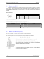
Pin
Label
I/O
Description
2
3
5
TXD
RXD
GND
output
input
-
Transmitter
Receiver
Ground
9 pin connector D-SUB MALE
Cable between decade and computer description (configuration 1:1)
Computer
Receiver
Transmitter
Ground
8.4.
D-Sub 1
2
3
5
D-Sub 2
2
Transmitter
3
Receiver
5
Ground
M-622
Remote control IEEE488 (optionaly)
The list of commands is valid for version of decade with IEEE488 interface.
The instrument performs the following functions based on IEEE488 bus commands:
SH1, AH1, T5, L3, RL1, DC1
The instrument also recognizes the following general commands:
DCL Device Clear - resets the instrument to its basic state
SDC Selected Device Clear - resets the instrument to its basic state
GTL Go To Local - switches the remote control off
LLO Local Lock Out - switches the local control off, the instrument
cannot be controlled from the front panel
Commands are identical to the commands for RS-232 interface. Detailed
description is shown in chapter 8.2.
21
Operation manual
MEATEST
M - 622 Precision Resistance Decade
8.5. Demo program
A simple operating program DecadeAssistant is supplied with the decade in order to provide
easy operation of the instrument from the computer, and to check the RS-232 line (IEEE488 bus) of
the instrument. The installation CD ROM contains a program (for MS WINDOWS only), you can
communicate with the instrument through standard serial line (IEEE488) with. For example, you can
set value or function on the decade. For IEEE488 connection this DecadeAssistant requires properly
configured National Instruments IEEE488 card.
Download on www.meatest.com.
Operation manual
22
M-622 Precision Resistance Decade
MEATEST
9. Module 19” (extra ordered option)
RTD simulator can be ordered as 19” module for easy assembling into a 19” rack. Module height
is 3HE.
10. Electric function
Resistance elements are switched to the output terminals through reed relays in binary code
system. The relays used are types with low thermoelectric voltage. The resistors are of foil or metal
type with low temperature coefficient. Metal housing is connected to the ground terminal only. The
board with resistors and relays creates independent mechanical block.
CPU unit with one-chip micro-controller generates all necessary internal control signals.
Calibration data and set-up parameters are saved in EEPROM memory.
11. Mechanical construction
Decade housing is standardised aluminium type one. Keyboard with display and output
terminals are located on the front panel. External power supply connector and RS-232 connector are
located on the rear panel. Internal battery is fixed to the rear panel inside the housing.
11.1.
Battery maintenance
Period for fully battery charging is approx. 40 hours. If the instrument has been stored for more
than 3 months without connected external power line adapter, battery should be charged.
23
Operation manual
MEATEST
11.2.
M - 622 Precision Resistance Decade
Battery replacement
Internal battery is sealed lead-acid maintenance-free long-life rechargeable battery with voltage
12V and capacity 2.6Ah.
To replace battery use following procedure:
Disconnect external power supply adapter and RS-232 (IEEE488) cable.
Switch decade off.
Dismount 4 screws located in the corners of the rear panel.
Remove slightly top cover.
Disconnect connectors from the battery and dismount metal belt to release battery.
Replace battery pack.
Connect fresh battery and mount it into the case in opposite procedure.
12. Ordering information – options
Bus
M622-V1xxx
M622-V2xxx
- RS232
- IEEE488
Additional functions
M622-Vx0xx
- none
M622-Vx1xx
- Short/Open function
Housing
M622-Vxx0x
M622-Vxx1x
- table version
- module 19“, 3HE
Manufacturer
MEATEST, s.r.o.
Zelezna 509/3, 619 00 Brno
Czech Republic
www.meatest.com
Operation manual
tel: +420 – 543 250 886
fax: +420 – 543 250 890
[email protected]
24