Download M192 Programmable AC/DC load
Transcript
M-192
Operation manual
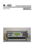
AC/DC Resistance Load
M-192 AC/DC Resistance load
MEATEST
Content
1.
USE OF THE INSTRUMENT .................................................................................................................... 4
2.
CONTENTS OF DELIVERY ..................................................................................................................... 4
3.
PREPARATION FOR USE ........................................................................................................................ 5
3.1.
3.2.
3.3.
4.
POWER-ON ............................................................................................................................................ 5
REPLACEMENT OF FUSE ......................................................................................................................... 5
SAFETY PRECAUTIONS ........................................................................................................................... 6
DESCRIPTION ............................................................................................................................................ 7
4.1.
4.2.
5.
FRONT PANEL ........................................................................................................................................ 7
REAR PANEL .......................................................................................................................................... 9
OPERATION ............................................................................................................................................. 10
5.1.
STANDARD MODE ................................................................................................................................ 10
5.2.
SETUP MODE - BASIC RULES ................................................................................................................ 11
5.3.
SETUP MODE ....................................................................................................................................... 11
6.3.1. Load configuration (Instrument) ................................................................................................... 11
6.3.1.1.
6.3.1.2.
6.3.1.3.
6.3.1.4.
6.3.2.
General settings (General) ............................................................................................................ 12
6.3.2.1.
6.3.2.2.
6.3.2.3.
6.3.2.4.
6.3.2.5.
6.3.2.6.
6.3.3.
Beeper setting (Beeps) .........................................................................................................................12
Display setting (Display) ......................................................................................................................13
Passwords setting (User access) ...........................................................................................................13
Language (LANGUAGE) .....................................................................................................................13
Device information (INFO) ..................................................................................................................13
Interface setting (Interface) ..................................................................................................................14
Protected area (Protected) ............................................................................................................ 14
6.3.3.1.
6.3.3.2.
6.
Simulated function (Function) .............................................................................................................11
Refresh cycle for Current and Power function (C/P refresh) ................................................................12
Deviation limit for Current and Power function (C/P dev.) .................................................................12
Output On/Off switching mode (Output switch.) .................................................................................12
Calibration constants (Calibration) ......................................................................................................14
Service setting (Service) .......................................................................................................................14
CALIBRATION ......................................................................................................................................... 16
6.1.
6.2.
RESISTANCE CALIBRATION .................................................................................................................. 16
VOLTMETER CALIBRATION (M-192A VERSION ONLY) ......................................................................... 17
7.
ERROR MESSAGES ................................................................................................................................ 18
8.
PERFORMANCE VERIFICATION TEST ............................................................................................ 19
9.
SYSTEM CONTROL ................................................................................................................................ 20
9.1.
9.2.
9.3.
IEEE-488 BUS PROPERTIES ................................................................................................................. 20
RS232 SERIAL LINE SETTING................................................................................................................ 20
COMMAND SYNTAX ............................................................................................................................. 21
10.
ELECTRIC FUNCTION........................................................................................................................... 26
11.
SPECIFICATION ...................................................................................................................................... 27
12.
ACCURACY .............................................................................................................................................. 28
13.
ORDERING INFORMATION – OPTIONS ........................................................................................... 28
14.
APPENDIX A M-192 MENU STRUCTURE ........................................................................................ 29
3
Version 15
Operation manual
MEATEST
M-192 AC/DC Resistance load
1. Use of the instrument
AC/DC Resistance Load M-192 is programmable resistance decade in range 15.000 Ohm to
300 kOhm. It is designed as power resistance decade (3000W) for testing AC/DC power sources,
transformers or generally as resistance load. Set resistance value is created via appropriate
combination of physical resistors. Actual set values are displayed on the front panel display. M-192 is
sophisticated instrument with its own re-calibration procedure. The procedure enables to correct any
deviation in resistance without any mechanical adjusting.
Instrument is especially suitable for automatic testing procedures. RS232 line (optionally
IEEE488 bus) is used for connecting decade to the computer.
2. Contents of delivery
AC/DC Resistance Load M-192
User’s manual
Power cable
Test leads 2 pcs
Test report
Operation manual
4
M-192 AC/DC Resistance load
MEATEST
3. Preparation for use
The instrument should be powered by 100 … 240 V – 50/60 Hz mains. Before powering on
the instruments, place it on a level surface. Do not cover the vents at the bottom/top sides and
the fan opening at the rear panel. Parameters of this instrument are guaranteed at 235 oC.
3.1. Power-on
Plug one end of the power cord into the connector located at the rear panel and connect the
other end of the power cord into a wall outlet.
Switch on the mains switch located at the front panel. Display is lit.
The resistance load performs internal hardware checks for 5 seconds. Configuration of the
instrument is displayed in the end of this test (version M-192 or M-192A).
After the tests conclude, instrument resets to its reference state, i.e. the following
parameters are set:
Function
Resistance
Set value
100 Ω
Output terminals
OFF
3.2. Replacement of fuse
Resistance load includes a fuse located near the mains connector at the rear panel. Replace the
fuse as follows:
Switch off the instrument
Remove the end of power cord from the mains connector at the rear panel.
Release the fuse using flat screwdriver and pull out the fuse holder.
Remove the fuse and replace it with new fuse of the same rating.
5
Operation manual
MEATEST
M-192 AC/DC Resistance load
3.3. Safety precautions
The instrument has been designed in Safety Class I according to EN 61010-1. The design
reflects the requirements of A2 amendment of the standard.
Safety is ensured by the design and by the use of specific component types.
The manufacturer is not liable for the damage caused by modification of the construction or
replacement of parts with non-original ones.
Safety symbols used on the equipment
Warning, reference to the documentation
Warning - risk of electric shock
Operation manual
6
M-192 AC/DC Resistance load
MEATEST
4. Description
4.1. Front panel
1
2
6
3
5
4
On the front panel there are located all main control keys, display and output terminals.
1.
Output terminals
Output resistance is available on R output terminals. Available is 2, 3 and 4-wire
connection.
2.
Display
Two-row alphanumerical display is used for displaying all information. Main value, i.e.
simulated output resistance is displayed in upper row. . In the lower row mesaured voltage connected
to the output terminals (M-192A only) is displayed.
Auxiliary information is displayed in lower row. Depending on status following symbols can be
displayed in right low corner:
keys 2, 4, 6 and 8 are switched to the cursor keys function (blue labels are valid)
load is in remote control via RS232 (IEEE488 optionally)
7
Operation manual
MEATEST
3.
M-192 AC/DC Resistance load
Keyboard
Numerical values can be entered from the numerical part of keyboard. Keys with number 2, 4, 6, 8
have also next meaning as display cursor keys. Except numerical there are following keys in the
keyboard:
Key
MENU
BSP
ESC
ENTER
4.
Meaning
enters to the SETUP/CALIBRATION MENU.
deletes last entered number.
cancels last entered value, cancels cursor keys function or leaves last set mode
confirms set value or confirms selected item in MENU or activates cursor keys function.
Cursor key function is indicated with symbol ( ) in right low corner of the display.
Power switch
Turns instrument AC power ON and OFF.
5.
Output On/Off
Connects (disconnects) selected resistance to the output terminals. Connected output is
indicated with green LED.
6.
Central ground terminal
Terminal with symbol “GND” is connected with the housing (PE).
Operation manual
8
M-192 AC/DC Resistance load
MEATEST
4.2. Rear panel
On the rear panel there are located power supply connector, interface RS-232 connector
(optionally IEEE488 connector) and serial number plate.
1
5
4
1
2
3
4
5
3
2
forced ventilation holes
power line entry
power line fuse
model plate
RS-232 (IEEE488) connectors
9
Operation manual
MEATEST
M-192 AC/DC Resistance load
5. Operation
5.1. Standard mode
After switching on load comes to standard mode. Following information is shown on the
display:
M-192 version
M-192A version
In the upper row generated resistance in [] is displayed. In the lower row mesaured voltage
connected to the output terminals (M-192A only) is displayed.
New resistance value can be set using cursor keys or direct via numeric keybord. Cursor keys
are active after pressing ENTER key. Numeric keyboard is active after pressing ESC key.
Use of cursor keys
Cursor keys are active after pressing ENTER key.
Function of cursor keys depends on the version of the load:
M-192 (basic version)
There is certain number of different resistance values (64) in range 15.000 to 4700 Ω. Cursor keys
switch between these discrete values and increase or decrease resistance value. Cursor keys
are not used.
M-192A (full version)
Any value in range 15.000 Ω to 300 kΩ can be set. Cursor keys increase or decrease resistance
value. Cursor keys change the cursor position.
Numerical keyboard
Operation manual
10
M-192 AC/DC Resistance load
MEATEST
Numeric keys are active after pressing ESC key.
New resistance value can be entered directly using numeric keys. New value is settled after pushing
ENTER key. BSP key deletes last entered number.
M-192 (basic version)
M-192A (full version)
5.2. Setup mode - Basic rules
In the Setup mode can be changed parameters of the resistance load. Parameters are atored in
EEPROM memory.
Setup menu is organized as tree type structure. Meaning of keys is:
„↑“, „↓“
- parameter selection
„ENTER“ - confirmation of selected parameter
„ESC“
- return one level back
Parameter’s value is displayed in square brackets – [ 50.652] Ω. In this mode is not possible to
change displayed value. Parameter should be switched to the edit mode. Edit mode is entered after
pressing „ENTER“ key. The parameter in edit mode is displayed between marks „<” and „>“ - <
50.652> Ω. In case parametr can’t be switched to edit mode you should use password with higher
access level – vide infra.
5.3. Setup mode
Access to the Setup mode is enabled after pushing the “ENTER” key from the Standard mode.
6.3.1. Load configuration (Instrument)
Item serves for configuration of instrument’s output. After pushing “↓” key next item (“General
“) is selected. After pushing “ENTER” key following menu is displayed:
6.3.1.1.
Simulated function (Function)
This item is available only in M-192A (full version). Load can simulate:
a) Resistance – constant resistance mode. Load simulates required resistance in [Ω].
b) Current – constant current mode. Load measures voltage connected to the R terminals
and sets output resistance according to the formula R = Measured voltage / Required
current. This resistance can be automatically refreshed (recalculated) according to the
state of “C/P refresh” parameter.
11
Operation manual
MEATEST
M-192 AC/DC Resistance load
c) Power – constant power mode. Load measures voltage connected to the R terminals and
sets output resistance according to the formula R = (Measured voltage)^2 / Required
power. This resistance can be automatically refreshed (recalculated) according to the
state of “C/P refresh” parameter.
6.3.1.2.
Refresh cycle for Current and Power function (C/P refresh)
This item is available only in M-192A (full version). Item defines method of regulation the
output in Current and Power function. One of following modes can be selected:
a) Off –calculated resistance is not changed.
b) One time – calculated resistance is changed one time.
c) 5 s – calculated resistance is changed (stabilized) 5 seconds after switching output On.
d) 10 s – calculated resistance is changed (stabilized) 10 seconds after switching output On.
e) 30 s – calculated resistance is changed (stabilized) 30 seconds after switching output On.
f) Continually – calculated resistance is changed (stabilized) if measured value (current or
power) differs from required more than “C/P – dev.” %. Allowed deviation is defined
in “C/P dev.” parameter.
6.3.1.3.
Deviation limit for Current and Power function (C/P dev.)
This item is available only in M-192A (full version). Item defines maximal deviation for
Current or Power in “Continually” refresh mode. Output value is refreshed if measured deviation is
higher. Any value in range 0.1 % to 10.0% can be entered.
6.3.1.4.
Output On/Off switching mode (Output switch.)
Parameter defines how is the output of the load connected and disconnected. One of following
modes can be selected:
a) Random-Fire –load is connected or disconnected immediatelly after pushing OUTPUT
ON/OFF key. This type of output switching is fastest.
b) Zero-Crossing – load waits after pushing OUTPUT ON/OFF key for zero cross of
connected voltage (100ms timeout). This type of output switching reduces produced
electromagnetic noise.
6.3.2. General settings (General)
General instrument’s settings are in this item. After pushing “↑” key previous item (“Load“) is
selected. After pushing “↓” key next item (“Protected “) is selected. After pushing “ENTER” key
following menu is displayed:
6.3.2.1.
Beeper setting (Beeps)
Configuration of generating sounds is in this item.
6.3.2.1.1.
Keyboard beep (Keyboard)
One of following items can be selected:
a) Off – no sound is generated after pushing the key.
Operation manual
12
M-192 AC/DC Resistance load
MEATEST
b) On – short beep is generated after pushing the key.
6.3.2.1.2.
Other beeps (Others)
Sounds produced by the instrument (except of keyboard) can be switched:
a) Off – no sound is generated
b) On – sound is generated
6.3.2.2.
Display setting (Display)
Configuration of display is in this item.
6.3.2.2.1.
Display backlight (Backlight)
Item enables to set the backlight of the display. One of following items can be selected: (Low ,
High).
6.3.2.2.2.
Message display time (Massage time)
Item enables to set the message display time. One of following items can be selected: (Normal,
Long).
6.3.2.3.
Passwords setting (User access)
Item enables to set user passwords.
6.3.2.3.1.
Calibration access password (Cal. password)
Item enables to set five digits password for access level “Calibration”.
6.3.2.3.2.
Service access password (Srvc. password)
Item enables to set five digits password for access level “Service”.
6.3.2.4.
Language (LANGUAGE)
Item enables to set the language. You can select one of following items: (English, Cesky,
Deutsch).
6.3.2.5.
Device information (INFO)
Item enables to read out device internal information.
6.3.2.5.1.
Serial number (Serial number)
Function displays instrument’s serial number as ‘xxxxxx’ (six digits).
6.3.2.5.2.
Firmware version (FW version)
Function displays internal firmware version.
13
Operation manual
MEATEST
M-192 AC/DC Resistance load
6.3.2.6.
Interface setting (Interface)
6.3.2.6.1.
RS232 parameters (RS232 Baud Rate)
Item is available only for RS232 version. Item enables to set the baudrate. You can select one
of following baud rates: 1200, 2400, 4800, 9600 and 19200.
6.3.2.6.2.
IEEE488 address (IEEE488)
Item is available only for IEEE488 version. Item enables to set the IEEE488 address. You can
select any integer value in range 1...30.
6.3.3. Protected area (Protected)
Protected settings (calibration constants and service settings) are in this item. Correct password
should be written before entering protected area. M-192 has two access levels for protected
parameter’s setting:
Calibration (calibration laboratory), default password is “00000” and can be changed by
the user
Service (only for authorized service)
Access level is defined by used password.
After pushing “↑” key previous item (“General “) is selected. After pushing “ENTER” key
following menu is displayed:
6.3.3.1.
Calibration constants (Calibration)
All calibration constants are store in internal eeprom.
6.3.3.1.1.
Resistance values (R constant)
In this menu resistance elements of the load can be recalibrated. Complete recalibration
procedure consists of measuring of 24 resistance values and entering their actually measured values.
Detailed description of calibration procedure is in chapter “Calibration”.
6.3.3.1.2.
Internal voltmeter (Voltage)
In this menu internal volmeter can be recalibrated. Complete recalibration procedure consists of
adjusting of 4 calibration points. Detailed description of calibration procedure is in chapter
“Calibration”.
6.3.3.2.
Service setting (Service)
Item is available only for service department after entering service password.
Operation manual
14
M-192 AC/DC Resistance load
6.3.3.2.1.
MEATEST
Internal state reading (View)
In this item can be displayed following information:
Fan speed: speed of fans.
Temp. heat sink: temperature of internal heat sinks.
Temp. others: temperature of frame and temperature of internal air.
CPU firmware: version of main CPU FW.
RE firmware: version of auxiliary CPU FW.
6.3.3.2.2.
Temperature sensors calibration (Temp. calibr.)
In this item can be adjusted offest of all internal temperature sensors (Real temp 1, Real temp 2,
Real temp 3, Real temp 4, Real temp 5, Real temp 6, Real temp 7).
15
Operation manual
MEATEST
M-192 AC/DC Resistance load
6. Calibration
In this mode resistance elements of the decade and voltmeter (M-192A only) can be
recalibrated. Access to the calibration mode is enabled after entering correct password. Please see
chapter “Protected area” how to enter (modify) calibration password. Calibration parameters are
stored in EEPROM memory.
6.1. Resistance calibration
In Resistance calibration mode can be changed parameters of the resistance load. For calibration is
required ohmmeter with ranges 10 Ω … 200 MΩ and required accuracy.
Table contains nominal values of calibration points and required recalibration accuracy:
Standard
Nominal value
Required Accuracy
R1
48
10 m
R2
50
10 m
R3
75
15 m
R4
150
20 m
R5
300
40 m
R6
600
80 m
R7
1200
150 m
R8
2400
300 m
R9
4700
600 m
R10
9220
1
R11
18.2 k
2
R12
35.2 k
5
R13
69.3 k
10
R14
136 k
20
R15
267 k
40
R16
522 k
100
R17
1030 k
500
R18
2020 k
1 k
R19
3990 k
2 k
R20
7900 k
10 k
R21
15.7 M
50 k
R22
30 M
200 k
R23
60 M
500 k
R24
120 M
2 M
Note: M-192 (basic version) contains resistance values R1…R9 only. M-192A (full version)
contains all resistances (R1…R24).
Process of calibration consists of measuring partial resistances and writting their actual values
into the decade:
Set the first calibration point (resistance element). Use keys to select the element.
Operation manual
16
M-192 AC/DC Resistance load
MEATEST
Press ENTER key to confirm selected resistance.
Press OUTPUT ON key to connect selected resistance to the output terminals.
Measure resistance of the selected element. Use ohm-meter with appropriate accuracy in 4wire connection.
Change mode of keyboard to cursor mode by pushing the ENTER key.
Change calibration value of selected resistance if needed.
Confirm new calibration data by pushing ENTER key or leave without changes by ESC
key.
Repeat above described procedure for all resistance elements.
6.2. Voltmeter calibration (M-192A version only)
In Voltmeter calibration mode can be changed parameters of internal AC/DC voltmeter. For
calibration is required voltage calibrator with ranges up to 250V and required accuracy. Alternatively
can be used voltage source and accurate voltmeter.
Table contains nominal values of calibration points and required recalibration accuracy:
Calibr. point
Nominal value
Required Accuracy
U DC pos
100 V
10 mV
U DC neg
-100 V
10 mV
U AC low
50 V
25 mV
U AC high
250 V
100 mV
Calibration procedure:
Set the first calibration point (U DC pos).
Press ENTER key to confirm selected point.
Connect the voltage calibrator to the load (R terminals) and set the output value +100V dc.
Change mode of keyboard to cursor mode by pushing the ENTER key.
Change exact value of connected DC voltage. It should be close to the nominal value (+/10%).
Confirm new calibration data by pushing ENTER key or leave without changes by ESC
key.
Repeat above described procedure for all calibration points.
17
Operation manual
MEATEST
M-192 AC/DC Resistance load
7. Error messages
If an error occurs during the loads’s operation or control, error message is displayed on the
display. Errors can be caused by:
Incorrect control using the front panel, i.e. attempts to force a prohibited mode, e.g.
setting an out-of-range value, overloading of output terminals etc.,
Calibrator’s fault.
Sample error message which appears is shown bellow.
The following table lists all error messages, their meaning and simple troubleshooting.
Error message
WARNING:
Temperature over
WARNING:
Fanner blocked
ERROR xx
Operation manual
Description
Load overheated. Disconnect external source.
Ambient temperature is too high or forced
ventilation holes are blocked.
Fan does not work. Forced ventilation is blocked.
Internal error. Turn the load off and after 5 s turn
on. If the error will appear again, contact
manufacturer.
18
M-192 AC/DC Resistance load
MEATEST
8. Performance verification test
This chapter describes how to verify parametrs of the instrument. Verification procedure is
based on measuring resistance on the load output terminals with standard multimeter in recommended
points.
Required equippment
Ohm-meter nominal accuracy 0.01% in range 10 to 300 k (type Agilent 34401A or similar)
Load setting
Switch decade to the resistance function. Connect standard multimeter to the decade output terminals.
Use four-wire connection technique.
Range of the test
output resistance on terminals R4W checking
Procedure
Use following procedure to perform parameters verification test.
1. Switch both instruments on and let them for 1 hour stabilise in the laboratory with ambient
temperature 232 oC. Connect resistance decade terminals R4W to the standard ohm-meter
(multimeter).
2. Check resistance value in points according to Table I, for M-192A (full version) also according to
Table II
Table I. M-192 (all versions) maximal deviations
Nominal value []
15.000
50.000
100.000
600.00
1200.0
4700.0
Max. deviation [m]
45
80
100
600
1200
4700
Table II. M-192A (full version) maximal deviations
Nominal value [k]
10.00
30.00
100
300
19
Max. deviation []
10
30
200
1500
Operation manual
MEATEST
M-192 AC/DC Resistance load
9. System control
The load is equipped with RS232 serial line as standard. IEEE-488 bus is optional. System
connectors are located at the rear panel. For the remote control to work properly, interface parameters
must be set in the system menu. For RS232 line communication speed can be set (1200 to 19200 Bd).
For IEEE-488 bus, an address from range 0 to 30 is allowed. The calibrator can be only controlled by
one of interfaces at a time. It is therefore necessary to select one of the interfaces (RS232/IEEE488)
using the system menu.
9.1. IEEE-488 bus properties
The instrument performs the following functions based on IEEE488 bus commands:
SH1, AH1, T5, L3, RL1, DC1, SR1
The instrument also recognizes the following general commands:
DCL Device Clear
reset the calibrator
SDC Selected Device Clear
reset the calibrator
EOI End or Identify Message Terminator close the message
GTL Go To Local
close remote control mode
LLO Local Lock Out
local control locked
9.2. RS232 serial line setting
To transfer the data using RS232 bus, 8N1 data format is used, i.e. each data word includes 8
bits, no parity and one stop bit. The communication speed can be set using the system menu.
Available values: 1200, 2400, 4800, 9600 and 19200 Bd.
RS-232 connector layout
Pin
Name
Direction
Description
2
3
5
TXD
RXD
GND
Output
Input
-
Transmitter
Receiver
Ground
9-pin connector D-SUB FEMALE
Cable between the calibrator and PC (configuration 1:1)
PC
D-Sub 1 D-Sub 2
Receiver
2
2
Transmitter
Transmitter
3
3
Receiver
Ground
5
5
Ground
Operation manual
Calibrator
20
M-192 AC/DC Resistance load
MEATEST
Note:
It is not possible to send or receive data over RS232 when the calibrator is not in remote mode.
You should use the command SYST:REM or SYST:RWL.
9.3. Command syntax
The commands described in this chapter can be issued through all buses (RS232/IEEE488).
All commands listed in this chapter are explained in two columns:
KEYWORD and PARAMETERS.
KEYWORD column includes the name of the command. Each command includes one or more
keywords. If a keyword is in brackets ( [ ] ), it is not mandatory. Non-mandatory commands are used
only to achieve compatibility with language standard SCPI.
Capitals designate the abbreviated form of the commands; extended form is written in
lowercase.
Command parameters are in brackets (<>); each parameter is separated using a comma.
Parameters in brackets ( [ ] ) are not mandatory. Line ( | ) means “or” and is used to separate several
alternative parameters.
Semicolon ‘;’ is used to separate more commands written on one line.
E.g. :SAF:LR 100.5;:OUTP ON
Note (only for RS232): Each command must end in <cr> or <lf>. Both codes <crlf> can be
used at the same time. The instrument performs all commands written on one line of the program after
it receives <cr>, <lf> or <crlf> code. Without this code, the program line is ignored.
Description of abbreviations
<DNPD> = Decimal Numeric Program Data, this format is used to express decimal number with or
without the exponent.
<CPD> = Character Program Data. Usually, it represents a group of alternative character
parameters. E.g. {ON | OFF | 0 | 1}.
<SPD> = String Program Data. String value consisting from more parts. It is used for date/time
setting.
?=
A flag indicating a request for the value of the parameter specified by the command. No
other parameter than the question mark can be used.
(?) =
A flag indicating a request for the parameter specified by the command. This command
permits a value to be set as well as requested.
<cr> =
carriage return. ASCII code 13. This code executes the program line.
<lf> =
line feed. ASCII code 10. This code executes the program line.
21
Operation manual
MEATEST
M-192 AC/DC Resistance load
OUTPut subsystem
This subsystem enables to activate or deactivate the instrument output.
Keyword
Parameters
OUTPut
[:STATe](?)
<CPD> { ON | OFF }
:SYNChronization(?)
<CPD> { ON | OFF }
OUTP[:STAT](?) <CPD> { ON | OFF }
This command activates or deactivates output terminals.
ON - activates the output
OFF - deactivates the output
If query is sent, calibrator returns ON if the output is active or OFF if it is inactive.
Example: OUTP ON - activates the output
OUTP? - the instrument returns ON or OFF
OUTP:SYNC(?) <CPD> { ON | OFF }
This command how is the output of the load connected and disconnected.
OFF – without synchronization to the input signal
ON – synchronized zero crossing output connection/disconnection
If query is sent, instrument returns ON or OFF according to selected synchronization mode.
Example: OUTP:SYNC OFF selects output switching without synchronization to the input signal
OUTP:SYNC? Calibrator returns ON or OFF
FUNCtion subsystem (M-192A only)
This subsystem sets function of the load.
Keyword
FUNCtion?
[FUNCtion]
:RESistance (?)
:POWer (?)
:CURRent (?)
Parameters
<CPD> { RES | POW | CURR }
<DNPD>
<DNPD>
<DNPD>
FUNC(?) <CPD> { RES | POW | CURR }
This command sets the output function of the load.
RES - constant resistance output function. Load simulates required resistance in [Ω].
POW – power output function.
CURR – current output function.
If query is sent, calibrator returns active output function.
Example: FUNC RES – sets resistance output function
FUNC? - the instrument returns RES, POW or CURR
[FUNC:]RES(?) <DNPD>
This command sets the output resistance value.
<DNPD>
Parameter represents the value of the output resistance expressed in Ω.
Operation manual
22
M-192 AC/DC Resistance load
MEATEST
If query is sent, calibrator returns the value of output resistance using standard exponential
format. Example: 110.1 Ω is returned as 1.101000e+002.
Example:
Resistance 230.5Ω:
FUNC:RES 230.5
Note:
Command selects resistance output function.
[FUNC:]POW(?) <DNPD>
This command sets the output power value.
<DNPD>
Parameter represents the value of the output power expressed in W.
If query is sent, calibrator returns the value of output power using standard exponential
format. Example: 1101 W is returned as 1.101000e+003.
Example:
Power 230W:
FUNC:POW 230
Note:
Command selects power output function.
[FUNC:]CURR(?) <DNPD>
This command sets the output current value.
<DNPD>
Parameter represents the value of the output current expressed in A.
If query is sent, calibrator returns the value of output current using standard exponential
format. Example: 2 A is returned as 2.000000e+000.
Example:
Current 2.5A:
FUNC:CURR 2.5
Note:
Command selects current output function.
MEASure subsystem
This subsystem allows controling the internal multimeter.
Keyword
Parameters
MEASure
:VOLTage?
:CURRent?
:POWer?
MEAS:VOLT?
This query returns value measured by the voltmeter.
Example: MEAS:VOLT? Instrument returns measured value
MEAS:CURR?
This query returns value measured by the voltmeter and converted to current.
23
Operation manual
MEATEST
Example:
M-192 AC/DC Resistance load
MEAS:CURR? Instrument returns measured value
MEAS:POW?
This query returns value measured by the voltmeter and converted to apparent power.
Example: MEAS:POW? Instrument returns measured value
CONFigure subsystem
This subsystem allows setting instrument’s basic parameters.
Keyword
Parameters
CONFigure
:REFResh(?)
:DEViation (?)
<CPD> { OFF | 1x | 5x | 10x | 30x | CONT }
<DNPD>
CONF:REFR(?) <CPD> { OFF | 1x | 5x | 10x | 30x | CONT }
This command defines method of regulation the output in Current and Power function. One of
following modes can be selected:
OFF –calculated resistance is not changed.
1x – calculated resistance is changed one time.
5s – calculated resistance is changed (stabilized) 5 seconds after switching output On.
10s – calculated resistance is changed (stabilized) 10 seconds after switching output On.
30s – calculated resistance is changed (stabilized) 30 seconds after switching output On.
CONT – calculated resistance is changed (stabilized) if measured value (current or power)
differs from required more than “C/P – dev.” %. Allowed deviation is defined in “C/P dev.”
Parameter (command CONF:REFR:DEV)
If query is sent, instrument returns OFF, 1x, 5s, 10s, 30s or CONT according to selected multimeter
method.
Example: CONF:VOLT OFF without refresh the output in current and power mode
CONF: DEV(?) <DNPD>
This command defines maximal allowed deviation for continual regulation in functions CURR
(current) and POW (power).
<DNPD>
Parameter represents allowed deviation expressed in %.
If query is sent, calibrator returns the value of deviation using standard exponential format.
Example: 1 % is returned as 1.000000e+000.
Example:
Deviation 2%:
CONF:DEV 2
SYSTem subsystem
The subsystem enables to control various functions from the MENU.
SYSTem
:ERRor?
:REMote
:RWLock
:LOCal
SYST:ERR?
Query the instrument’s error queue. Detected errors are placed in the queue. This query returns the
first error from the queue. The queue is type “first in, first out”. The error is deleted after reading.
Operation manual
24
M-192 AC/DC Resistance load
MEATEST
The response is in the form of 'String Program Data', and consists of two elements: a code number and
error message.
If all errors are read calibrator returns message 0,”No Error”.
In case of overflow the error queue the last error in the queue is –350,”Queue overflow”. Also the
earliest errors remain in the queue, and the most recent error is discarded.
Example:
SYST:ERR?
Error Queue
The Error Queue stores error messages. They are placed in a “first in, first out” queue. The
queue is read destructively using the query command “SYSTem:ERRor?” to obtain a code
number and errro message. The query “SYSTem:ERRor?” can be used to read errors in the
queue until it is empty, when the message “0, No Error” will be returned.
SYST:REM
This command places the instrument in the remote mode for RS232 operation. All keys on the front
panel, except the ESC (LOCAL) key, are disabled.
Note:
It is not possible to send or receive data over RS232 or Ethernet when the calibrator is not in remote
mode.
SYST:RWL
This command places the instrument in the remote mode for RS232 operation. All keys on the front
panel are disabled.
SYST:LOC
This command returns the instrument in the local mode. This command is for RS232 interface only.
I/D (instrument identification)
*IDN?
This command returns the identification of the manufacturer, model, serial number and
firmware revision.
The reply is formatted as follows:
MEATEST,M-192,100002,1.22
Clear status
*CLS
This command clears the Error Queue.
25
Operation manual
MEATEST
M-192 AC/DC Resistance load
10. Electric function
Resistance elements are switched to the output terminals through relays in binary code system.
The resistors are very stable power resistors with low temperature coefficient. Resistors are mounted
on the heat sink. Metal housing is connected to the ground terminal (PE) only.
CPU unit with one-chip micro-controller generates all necessary internal control signals.
Calibration data and set-up parameters are saved in EEPROM memory.
Operation manual
26
M-192 AC/DC Resistance load
MEATEST
11. Specification
Only values, functions, ranges with signed accuracy in relative or absolute expression or where
limits are specified, are guaranteed.
Resistance range *
:
Resolution
:
Temperature coefficient
:
Maximal dissipation power
Maximal voltage
Connection of output terminals
Frequency range
Working mode
:
:
:
:
:
Reaction time **
Terminals
Interface
Reference temperature
Working temperature
Storing temperature
Housing
Dimensions
Weight
:
:
:
:
:
:
:
:
:
15 - 4700 (basic version)
15 - 300 k (version M-192A)
0.1 to 1 for M-192 version
0.001 to 1 k for M-192A version
< 10 ppm/ C (1 - 10 k)
< 25 ppm/ C (> 10 k)
3000 W
250 Vrms
2, 4 wire
0 (DC) to 10 kHz
constant Resistance
constant Power (simulation)
constant Current (simulation)
30 ... 100 ms
instrument terminals diameter 4mm, gold plated
RS232 as standard (IEEE488 optionally)
+18 C … +28 C
+5 C … +45 C
-10 C … +60 C
metal
W 430 mm, H 190 mm, D 500 mm
15 kg
Isolation resistance between output terminals and housing :
> 2 G (at 500V DC)
* Basic version M-192 allows to select between 64 fixed resistance values. Nominal values of resistancis are
15.0, 15.5, 16.0, 16.5, 17.0, 17.5, 18.0, 18.5, 19.0, 19.5, 20, 21, 22, 23, 24, 25, 26, 27, 28, 29, 30, 32, 34, 36,
38, 40, 42, 44, 46, 48, 50, 55, 60, 65, 70, 75, 80, 85, 90, 95, 100, 110, 120, 130, 140, 150, 160, 180, 200, 220,
240, 270, 300, 340, 400, 480, 600, 680, 800, 960, 1200, 1590, 2400 and 4700
** Reaction time means time interval between setting up value from front panel or receiving command from remote control
bus and settling set-up value on output terminals.
Notes:
Only data shown with tolerance or with band of limits are tested. All other values have
informative character.
During over-switching, resistance circuit is opened for a period about 40 ms.
27
Operation manual
MEATEST
M-192 AC/DC Resistance load
12. Accuracy
Specified accuracy is valid after 10 minutes warm up in temperature range 23 ± 5 oC.
Uncertainties include long-term stability, temperature coefficient, linearity, load and line regulation
and traceability of factory to National calibration standards. Accuracies assigned in % are related to
the set value. Specified accuracy is one-year accuracy.
Resistance accuracy (M-192A only up to 4700 )
Range
Accuracy
15.000 - 99.999
0.1 % + 30 m
100.000 - 3.000 k
0.1 %
3.001 k - 30.00 k
0.1 %
30.1 k - 100.0 k
0.2 %
101 k - 300 k
0.5 %
Internal voltmeter (M-192A only)
Range
Accuracy
1.0 - 299.9 V
DC
AC
0.1 % + 0.2 V
0.2 % + 0.2 V
Frequency response (M-192A)
Max. AC/DC difference
R
100 Hz
1 kHz
10 kHz
15 Ω
0,01 %
0,01 %
0,05 %
100 Ω
0,01 %
0,04 %
0,40 %
1000 Ω
0,04 %
0,40 %
4,00 %
10 kΩ
0,40 %
4,00 %
100 kΩ
4,00 %
13. Ordering information – options
M-192-Vxxxx
M-192A-Vxxxx
- basic version (15 - 4700)
- extended version (15 - 300k)
Remote control
M-192-V0xxx
M-192-V2xxx
- RS232
- IEEE488
Housing
M-192-Vxx0x
M-192-Vxx1x
- table version
- module 19“, 4HE
Example of the order:
M-192A-V2000 - resistance load 15 - 300k, IEEE488 bus, table version
Operation manual
28
M-192 AC/DC Resistance load
MEATEST
14. Appendix A M-192 Menu structure
Setup menu has following folders:
- Load
- General
- Protected
M-192 has two access levels for protected parameter’s setting:
Calibration (calibration laboratory)
Service (service organization)
Access level is defined by used password.
Load
Function
C/P -refresh
C/P –dev.
Ourput switch.
Meter
General
Beeps
Resistance
Current
Power
Off
One time
5s
10 s
30 s
Continually
0.1 – 10 %
Random-Fire
Zero-Crossing
Voltage
Current
Power
Keyboard
Others
Display
Backlight
Message time
User access
Language
Info
Interface
Protected
Calibration
Service
29
Cal. password
Srvc. password
English
Cesky
Deutsch
Serial number
FW version
Active
RS232 BaudRate
IEEE488 addr.
R constant
Voltage
View
Off
On
Off
On
Low
High
Normal
Long
RS232/IEE488
R1…Rxx
U DC pos
U DC neg
U AC low
U AC high
Fan speed
Temp. heat sink
Temp. others
CPU firmware
RE firmware
Operation manual
MEATEST
M-192 AC/DC Resistance load
Temp. calibr.
Real temp:A
Real temp:B
Real temp:C
Real temp:D
Real temp:Air
Real temp:Case
Manufacturer
MEATEST, spol.s r.o.
Zelezna 509/3, 619 00 Brno
Czech Republic
www.meatest.com
Operation manual
tel: +420 – 543 250 886
fax: +420 – 543 250 890
[email protected]
30


