1
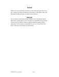
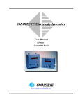
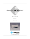
Oxygen Meter
User Manual
Monday, July 23, 2007
1.
Outline .......................................................................................................................... 2
2.
Program ........................................................................................................................ 3
3.
2.1.
Environment for program execution .................................................................... 3
2.2.
Installation ............................................................................................................ 3
2.3.
Un installation ...................................................................................................... 3
2.4.
USB driver installation ........................................................................................ 3
2.5.
Text-to-Speech Engine .......................................................................................... 3
Operation...................................................................................................................... 4
3.1.
Preparation ........................................................................................................... 4
3.2.
Execution............................................................................................................... 4
3.3.
Main window ......................................................................................................... 5
3.4.
Zero_Point calibration .......................................................................................... 7
3.5.
Gas calibration ...................................................................................................... 8
3.6.
Liq Calibration ...................................................................................................... 9
3.6.1.
Liq calibration at the temperature measurement enabled.......................... 9
3.6.2.
Liq calibration at the temperature measurement disabled ....................... 10
3.7.
Gas Start ............................................................................................................. 11
3.8.
Liq Start .............................................................................................................. 13
3.9.
Data transfer to Excel etc ................................................................................... 14
3.10.
Changing language.......................................................................................... 14
4.
Restrictions................................................................................................................. 15
5.
Notes for Operation.................................................................................................... 15
References.......................................................................................................................... 16
Appendix-1 DC Voltage Measurement Circuit................................................................. 17
(1/19)
1. Outline
This is an educational oxygen meter to understand oxygen concentration in gas or
liquid.
This measures oxygen concentration and temperature, and then displays them
in a graph. Following shows the measurement system.
The oxygen sensor is a Galvanic battery type sensor. This sensor generates a DC
voltage proportional to the oxygen concentration.
The temperature sensor is LM35DZ transistor type sensor from the National
Semiconductor. This generates a DC voltage proportional to the temperature.
The DC voltage measurement circuit amplifies the DC voltages from the both sensors,
converts to digital values, and sends them to a Personal computer via USB cable, The
personal computer displays measured values and also speaks the values by a speaker..
Features of the Oxygen sensor
(1)
Low cost. Easy reproducible.
(2)
Students can easily construct this sensor by themselves
(3)
Electrode liquid used for sensor is safe for human.
(4)
Measure both gas oxygen concentration and dissolved oxygen concentration
Features of the Temperature sensor
(1)
It is waterproofed to measure liquid temperature.
(2)
It is high precise by using semiconductor PN junction voltage.
(2/19)
Features of this measurement system
(1)
The DC voltage measurement circuit does not require a DC Power supply, since the
DC power is supplied from the USB cable..
(2)
Calibration is easy and automatic..
(3)
Measured data is displayed in real time.
(4)
Has an Excel interface
(6)
Supports bi-language..
(7)
Measured values can be spoken from a PC speaker.
2. Program
2.1.
Environment for program execution
Windows XP, WindowsVista
Runtime version of Visual Basic 6.0
Microsoft Text-to-Speech Engine
Speaker
2.2.
Installation
Following are files for installation.
z
setup.exe
z
setup.LST
z
XxxTmpMeterCAB
Double click the setup.exe, and follow the procedure guided by the installation program.
2.3.
Un installation
Uninstall the installed program from the Windows control panel.
2.4.
USB driver installation
The DC voltage measurement circuit requires a special USB driver. When the USB
cable is attached to the PC, the PC requires the USB driver installation. The USB
driver is saved in a supplied CD-ROM.
Insert the CD-ROM and install the USB
driver by setting the searching path to the CD-ROM.
When the USB driver is not installed completely, the following message will be
displayed.
"Can not find USB-COM Port !"
2.5.
Text-to-Speech Engine
Install the Text-Speech Engine.
Those engine files can be downloaded from the next url page.
(3/19)
Microsoft Agent download page for end-users
http://www.microsoft.com/msagent/downloads/user.asp
(1)SAPI 4.0 runtime support:
Download the Microsoft SAPI 4.0a runtime binaries (824 KB exe)
File name: Spchapi.exe
(2)Text-to-speech engines:
Download selected engine
Lernout & Hauspie@TTS 3000 TTS engine – Japanese(3MB exe)
File name: lhttpsjpj.exe
Downloaded files are already saved in the CD-ROM. You can install engines from those
files.
3. Operation
3.1.
Preparation
Connect the DC Voltage measurement circuit to the PC using the USB cable.
3.2.
Execution
Double click the program file, XxxTmpMeter.exe, or its short cut icon.
Main windows will be opened.
(4/19)
3.3.
Main window
Main window when the temperature measurement is enabled.
(5/19)
Main window when the temperature measurement is disabled.
Zero_Point calibration: Calibrates offset voltage of the DC Voltage measurement circuit
for oxygen concentration measurement.
Gas Calibration: Calibrates the oxygen concentration in gas.
Liquid calibration: Calibrates the dissolved oxygen concentration in liquid.
Setting: Enable or disable the temperature measurement function.
Help: Displays version and how to use this software.
Japanese: Changes language to Japanese;
English: Changes language to English
COM Port: Displays assigned com port. The DC Voltage measurement circuit has
USB-Serial conversion circuit in which the USB driver automatically assigns a COM
port for the USB channel.
Excel Out: When checked, the software displays measured data in Excel after
measurement completion.
Voice Out: When checked, the measured value is spoken by PC speaker
Sampling interval and count:
sampling interval and count selections from this combo
(6/19)
boxes.
Sensor out (mV): Sensor output voltage from the DC Voltage measurement circuit.
Oxygen(%): Oxygen concentration. This is converted value from the above sensor out
voltage.
Temp(°C): Temperature. This is converted value from the temperature sensor our
voltage.
Lower text boxes: Displays sampling interval, sampled count, measured oxygen
concentration and temperature.
Graphic window: Displays graphically the measured oxygen concentration and
temperature.
Gas start: Starts oxygen concentration measurement in gas.
Liq start: Starts dissolved oxygen concentration measurement in liquid.
Stop: Stops measurement.
Exit: Exits from this program.
Copy: Copies the measured data to a Window clip board.
Excel: Displays the measured data in Excel.
File: Files the measured data into a file.
3.4.
Zero_Point calibration
This calibrates offset voltage from Oxygen sensor.
When the Zero_Point calibration menu is clicked, the following window will be opened.
Short input terminals from oxygen sensor, and click the start button. Sensor output
voltage is measured 10 times and average value is saves as an offset calibration voltage.
(7/19)
Hereafter sensor output voltage will be compensated by this value. This calibration is
required only one time after when DC voltage measurement circuit is connected to the
PC.
3.5.
Gas calibration
Sensor out voltage from pure atmosphere of gas concentration 20.9% is used for gas
oxygen concentration calibration.
When the Gas calibration menu is clicked, the following window will be opened.
Set oxygen sensor in pure atmosphere, click the start button. Sensor output voltage is
measured 10 times and average value is automatically saves as a gas calibration
voltage.
(8/19)
3.6.
Liq Calibration
Saturated dissolved oxygen concentration in pure water depends on water
temperature.
The relation between the saturated dissolved oxygen concentration and
the temperature is measured and booked.
The temperature and the sensor out voltage
from oxygen saturated dissolved pure water are used for dissolved oxygen concentration
calibration.
3.6.1. Liq calibration at the temperature measurement enabled
Both the temperature and the oxygen concentration are measured at the same time.
When the Liq calibration menu is clicked, the following window will be opened.
(9/19)
Set oxygen sensor and temperature sensor in pure water, click the start button.
Oxygen sensor output voltage and temperature are measured 10 times and average
values are calculated. The temperature and the saturated oxygen sensor out voltage for
the temperature are automatically saved as dissolved oxygen calibration values.
3.6.2. Liq calibration at the temperature measurement disabled
The temperature is measured by another sensor.
When the Liq calibration menu is clicked, the following window will be opened.
Key in the temperature value and set oxygen sensor in pure water, click the start
button. Oxygen sensor output voltage is measured 10 times and average values are
calculated. The temperature and the saturated oxygen sensor out voltage for the
(10/19)
temperature are automatically saved as dissolved oxygen calibration values.
3.7.
Gas Start
This starts gas oxygen concentration measurement. Select sampling interval and count,
and click the Gas start button.
Lower text boxes display measured gas oxygen concentration and temperature.
Lower picture window displays the measured data graphically.
When Excel out flag is checked, the measured data is displayed by Excel after
measurement completion.
(11/19)
(12/19)
3.8.
Liq Start
This starts dissolved oxygen concentration measurement. Select sampling interval and
count, and click the Liq start button
When the measurement is for dissolved oxygen, the back ground colors of data are
blue.
Lower text boxes display measured dissolved oxygen concentration and temperature.
Lower picture window displays the measured data graphically.
When Excel out flag is checked, the measured data is displayed by Excel after
measurement completion.
(13/19)
3.9.
Data transfer to Excel etc
Lower text boxes display measured oxygen concentration and temperature.
Excel button displays the measured data in Excel.
Copy button copies the measured data into Window clip board. The clip board data can
be pasted in Excel.
File button files the measured data in a file.
3.10. Changing language
Clicking Japanese menu changes language to Japanese.
Clicking English menu changes language to English.
(14/19)
4. Restrictions
(1) One PC can use only this one oxygen meter.
(2) When Excel is used, Excel license from Microsoft is required.
(3) Temperature sensor is LM35DZ from the National Semiconductor.
This works from 0°C to 50°C.
(4) In this version, the Text-to-Speech engine can not work for English language.
5. Notes for Operation
(1) Temperature sensor is water resistant. Use the temperature sensor at the
temperature range from -10 °C to 60°C.. Usage outside this range will damage the
sensor.
(2) When you insert or remove the USB cable, handle the USB cable at fixing the USB
connector.
(3) To work with Text-to-Speech function, the software must be installed completely and
a speaker must be attached to the PC.
(4) To follow the Text-to-Speech function, the sampling time must be greater than 3
seconds..
(15/19)
.
References
[1] Mitsuo Takahashi “ Trail and Experiment of Oxygen sensor”,
Transistor Gijytsu ( Japanese),
12, 2003
(16/19)
Appendix-1 DC Voltage Measurement Circuit
(17/19)
Hereafter shows adjustments and cable connections. Most adjustments have been
executed before shipment. Usually adjustments are not needed for users.
z
Terminal Block TB1
This has three terminals. This connects temperature sensor.
TB1-1: VCC (Red wire)
TB1-2: Temperature sensor out (White wire)
TB1-3:: GND (Black wire)
z
Terminal Block TB2
This has two terminals. This connects oxygen sensor.
TB2-1: Oxygen sensor out (Red wire)
TB2-2: GND (Black wire)
z
Jumper J1
This selects temperature sensors.
Jumper between J1-1 and J1-2: Internal temperature sensor.
(Note: Now internal temperature sensor is not implemented.)
Jumper between J1-2 and J1-3: External temperature sensor.
z
Jumper J2
This selects mode of oxygen sensor out.
Jumper between J1-1 and J1-2: Oxygen sensor out is current.
Jumper between J1-2 and J1-3: Oxygen sensor out is voltage..
z
Jumper J3 & J4
This selects sensor types
Jumper J3: Oxygen sensor
Jumper J4: Other sensor.
z
Variable resister VR1
This adjusts amplifier gain of temperature sensor out voltage so that the gain is 10.00.
This gain is already adjusted at shipment.
<How to adjust VR1>
Connect the temperature sensor, measure the voltage [V] between JB1-2 and JB1-3, and
adjust VR1 such that the temperature display is 100 times the measured voltage.
(18/19)
e.g.
.When the voltage [V] between JB1-2 and JB1-3 is 0.25 [V]. adjust VR1 such that the
temperature is 25°C.
z
Variable resister VR2
This adjusts amplifier gain of sensor out voltage.
For the oxygen sensor, this gain is already adjusted at shipment.
(19/19)