1
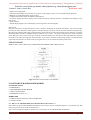
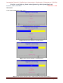
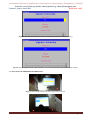
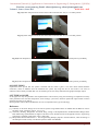
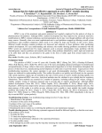
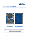
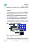
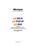
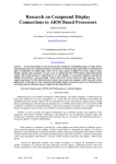
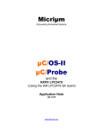
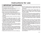
International Journal of Application or Innovation in Engineering & Management (IJAIEM) Web Site: www.ijaiem.org Email: [email protected], [email protected] Volume 2, Issue 6, June 2013 ISSN 2319 - 4847 GUI BASED LIQUID INDICATOR USING CORTEX M3 FOR INDUSTRY MONITORING SYSTEM J.Ramoji Guptha1, G.S.R Satyanarayana2 and P.Sambaiah3 1 P.G Student, School Of Electronics, Vignan University, Vadlamudi. Assistant Professor, School Of Electronics, Vignan University, Vadlamudi. 3 Assistant Professor, School Of Electronics, Vignan University, Vadlamudi. 2 ABSTRACT The Architectural evaluation in microcontroller development plays important role in the field of embedded systems. The embedded systems in industrial application can be developed around such microcontroller like ARM (advanced RISC machine) to optimize the system performance. This paper includes description about the real time application using ARM Cortex M3 and GUI. Most of the industrial application results are in digital values only. By using GUI we can view the values graphically like bar charts etc… Keywords: ARM, Cortex M3, GUI, RISC. 1. INTRODUCTION In this paper we developed a real time application for industries by using Cortex M3. In this paper we took one parameter as an example and we developed one real time application, that parameter is nothing but Reference level. For any industry this parameter plays a major role. In this paper we explained clearly about how will you develop a graphical display for that parameter above mentioned and also if the parameter crosses the limit which type of indication will come. This project plays an important role in the industries. In this case we used an advanced controller that is nothing but LPC1788. In that controller the processor is Cortex M3 [1] [8]. In this project we used an embedded processor. Its stability and reliability have been proved by lots of experiments, besides, it is also with low-power, tinyvolume, high integration density. This is applicable for real-time applications. This also increases the event response time of the tasks. It has less footprints. The ARM Cortex M3 is a next generation core that offers system enhancements such as modernized debug features and a higher level of support block integration. This is operating at up to a 120 MHz CPU frequency. The ARM Cortex-M3 CPU also includes an internal prefetch unit that supports speculative branches quadrature encoder interface, 4 general purpose timers, 6-output general purpose registers. So it is supplied with power by battery. 2. METHODOLOGY OF CORTEX M3 The LPC1788 is an ARM Cortex M3 based microcontroller for embedded applications requiring a high level of integration and low power dissipation. The Cortex M3 processor, based on the ARM architecture [7], is intended for cost-sensitive embedded applications. This MCU incorporates an efficient interrupt controller (NVIC), when the processor is idle, it can enter sleep mode, to be awake even when an interrupt occurs. The debug controller makes developing and testing software easier. Powerful trace features allow greater visibility into application operation. The ARM Cortex M3 is a next generation core that offers system enhancements such as modernized debug features and a higher level of support block integration. This is operating at up to a 120MHz CPU frequency. The ARM Cortex M3 CPU incorporates a 3-stage pipeline and uses Harvard architecture with separate local instruction and data buses as well as a third bus for peripherals. The peripheral complement of the LPC1788 includes up to 512 kb of flash program memory, up to 96 kb of SRAM data memory, up to 4032 byte of EEPROM data memory, External Memory Controller (EMC), LCD (LPC1788 only), Ethernet, USB device/host/OTG, a general purpose DMA controller, five UARTS, three SSP controllers, three i2c -bus interfaces, one eight-channel, 12-bit ADC, a 10-bit DAC, a quadrature encoder interface, four general purpose timers, two general purpose PWMS with six outputs each and one motor control PWM, an ultralow power RTC with separate battery supply and event recorder, a windowed watchdog timer, a CRC calculation engine, up to 165 general purpose I/O pins, and more. Volume 2, Issue 6, June 2013 Page 408 International Journal of Application or Innovation in Engineering & Management (IJAIEM) Web Site: www.ijaiem.org Email: [email protected], [email protected] Volume 2, Issue 6, June 2013 ISSN 2319 - 4847 2.1 FEATURES Operating voltage : 3.3v 32 bit microcontroller 120MHz clock frequency 3 stage pipelining Harvard architecture 512 kb flash memory 10/100 mbps Ethernet USB 2.0 full-speed device 3. LPC 1788 CONTROLLER The LPC1788 is an ARM Cortex M3 based microcontroller for embedded applications requiring a high level of integration and low power dissipation [5]. The LPC1788 adds a specialized flash memory accelerator to accomplish optimal performance when executing code from flash. The LPC1788 operates at up to 120MHz CPU frequency. The pin out of LPC1788 is intended to allow pin function compatibility with the LPC24xx and LPC23xx. 4. BLOCK DIAGRAM Fig 1 Block Diagram of GUI based Liquid Indicator 4.1 I/O’S Here by using some I/O’s like Serial cables, ADC, Ethernet ,and etc from these only we will take the inputs from the field (So, they are called as field inputs). After taking the inputs from the field it will sends information to the Cortex M3 processor .By using that information only it will do the required operation. 4.2 CORTEX M3 Here for this purpose we used LPC1788 controller. We already explained in detailed about that controller as above. Why we used this controller means it having some features they are better than the remaining controllers and also it having Cortex M3 processor. Here the Cortex M3 will take information from the I/O’s. Here the controller is having some add-on-cards.by using that add-on-card only it will collect the data from field, depending upon that data it will do the specific operation and computes the required controller output and sends output to the field. That output field is nothing but GUI. 4.3 GUI Here GUI is nothing but the graphical user interface. Here for this purpose we use GLCD (Graphical LCD) which is having touch screen. A graphical user interface (GUI) is a graphical display in one or more windows containing controls, called components that enable a user to perform interactive tasks. The user of the GUI does not have to create a script or type commands at the command line to accomplish the tasks. Unlike coding programs to accomplish tasks, the user of a GUI need not understand the details of how the tasks are performed.GUI components can include menus, toolbars, push buttons, radio buttons, list boxes, and sliders—just to name a few. For this purpose we use emWin software. 4.4 emWin emWin is designed to provide an efficient, processor- and display controller-independent graphical user interface for any application that operates with a graphical display. It is compatible with single-task and multitask environments, with a proprietary operating system or with any commercial RTOS. emWin is shipped as C source code. 4.4.1 Features of emWin: • Any (monochrome, grayscale or color) display with any controller supported (if the right driver is available). • May work without display controller on smaller displays. • Any interface supported using configuration macros. Volume 2, Issue 6, June 2013 Page 409 International Journal of Application or Innovation in Engineering & Management (IJAIEM) Web Site: www.ijaiem.org Email: [email protected], [email protected] Volume 2, Issue 6, June 2013 ISSN 2319 - 4847 • Display-size configurable. • Characters and bitmaps may be written at any point on the display, not just on even-numbered byte addresses. • Routines are optimized for both size and speed. • Compile time switches allow for different optimizations. • For slower display controllers, display can be cached in memory, reducing access to a minimum and resulting in very high speed. • Clear structure. • Virtual display support; the virtual display can be larger than the actual display. 4.5 GLCD Here the controller is having some GLCD. This is used for displaying the required information. The LCD controller provides all of the necessary control signals to interface directly to a variety of color and monochrome LCD panels [2]. Here the LCD supports both Super Twisted Nematic (STN) and active Thin Film Transistor (TFT) displays. It supports Dedicated DMA controller, Selectable display resolution (up to 1024 × 768 pixels), Supports up to 24-bit true-color mode. Here the LCD is touch screen [6]. From the cortex-M3 processor it will take the data and display the output at the LCD screen. Here we can get the required output. If you want to control the output of the system, it is possible at the output side also because it is touch screen by using that one if you can control the quantity of the input. 5. FLOW CHART HERE IT WILL TELL THE TOTAL OPERATION REGARDING THIS APPLICATION. Fig 2 Flow Chart of GUI based Liquid Indicator 6. SOFTWARE & HARDWARE REQUIRED SOFTWARE TOOLS EMBEDDED C IAR EMBEDDED WORK BENCH emWin GUI BUILDER MICROSOFT VISUAL C++ HARDWARE CORTEX M3 Plat form LPC1788 CONTROLLER J-LINK/J-TRACE 6.1 Why we use IAR Embedded Work Bench & Microsoft Visual C++? Why means by using IAR Embedded Work Bench if you want to see the simulation output it is not possible. For that reason only we will go to the Microsoft Visual C++. If you want to dump the program to hardware via j-link/j-trace we use IAR Embedded Work Bench. Volume 2, Issue 6, June 2013 Page 410 International Journal of Application or Innovation in Engineering & Management (IJAIEM) Web Site: www.ijaiem.org Email: [email protected], [email protected] Volume 2, Issue 6, June 2013 ISSN 2319 - 4847 6.2 IAR EMBEDDE WORK BENCH IAR Embedded Workbench integrated development environment (IDE). Using the IDE, you can design advanced project models. You create a workspace to which you add one or several projects. There are ready-made project templates for both application and library projects. Each project can contain a hierarchy of groups in which you collect your source files. For each project you can define one or several build configurations. In this by using embedded c we can write the program. Before going to start any program you can follow these steps Create a project Adding files to the project Setting project options Compile Linking and finally debugging. Fig 3 IAR Embedded Work Bench Work Space 6.3 MICROSOFT VISUAL C++ The PC simulation of emWin allows you to compile the same C source on your Windows PC using a native compiler and create an executable for your own application [3]. Doing so allows the following: • Design of the user interface on your PC (no need for hardware!). • Debugging of your user interface program. • Creation of demos of your application, which can be used to discuss the user interface. The resulting executable can be easily sent via e-mail. The emWin simulation requires Microsoft Visual C++ and the integrated development environment (IDE) which comes with it. You will see a simulation of your LCD on your PC screen, which has the same resolution in X and Y and can display the exact same colors as your LCD once it has been properly configured. The entire graphic library API and window manager API of the simulation are identical to those on your target system; all functions will behave in the very same way as on the target hardware since the simulation uses the same C source code as the target system. The difference lies only in the lower level of the software: the LCD driver. Instead of using the actual LCD driver, the PC simulation uses a simulation driver which writes into a bitmap. The bitmap is then displayed on your screen using a second thread of the simulation. This second thread is invisible to the application; it behaves just as if the LCD routines were writing directly to the display. Fig 4 Microsoft Visual C++ Work Space Volume 2, Issue 6, June 2013 Page 411 International Journal of Application or Innovation in Engineering & Management (IJAIEM) Web Site: www.ijaiem.org Email: [email protected], [email protected] Volume 2, Issue 6, June 2013 ISSN 2319 - 4847 6.4 GUI BUILDER SEGGER Microcontroller has developed a new tool to help the engineer shorten the time to create their application by replacing the tedious task of creating user interfaces in hand written code with a simple straight forward drag and drop interface. Using this tool, the emWin GUI Builder, a developer gets a jump start when creating their user interface with emWin. The emWin GUI Builder supports drag and drop operations as well as keyboard operations to create the interface. This allows quick placement of widgets and adds the ability for precision corrections of the layout while working in a convenient PC development environment. Once the design is ready to go, the developer saves the design as C-source code which can be loaded back into the editor to allow for later corrections to the layout even after adding code to further customize the interface. It is now even possible to permit an individual not familiar with C to design an engaging user interface while being confident in the fact that the generated code has been optimized for minimum overhead. By using GUI we can create the BELOW mentioned items and also so many items we can implement. Fig 5 GUI Builder Work Space 6.5 LPC 1788 controller Fig 6 LPC 1788 Controller kick start Kit The details about this controller mentioned above. 6.6 J-LINK/J-TRACE J-Link is a JTAG emulator designed for ARM cores [4]. It connects via USB to a PC running Microsoft Windows 2000 or later. J-Link has a built-in 20-pin JTAG connector, which is compatible with the standard 20-pin connector defined by ARM. Fig 7 J-Link/J-Trace Volume 2, Issue 6, June 2013 Page 412 International Journal of Application or Innovation in Engineering & Management (IJAIEM) Web Site: www.ijaiem.org Email: [email protected], [email protected] Volume 2, Issue 6, June 2013 ISSN 2319 - 4847 7. RESULTS 7.1 BY USING MICROSOFT VISUAL C++ Fig 8 (a) Initial Stage of the Controller Fig 8 (b) After 50% the Controller is in SAFE position Fig 8 (c) After 75% the Controller is in SAFE position Fig 8 (d) After 76% the Controller is Not in SAFE position [It Indicates Status Alarm!] Volume 2, Issue 6, June 2013 Page 413 International Journal of Application or Innovation in Engineering & Management (IJAIEM) Web Site: www.ijaiem.org Email: [email protected], [email protected] Volume 2, Issue 6, June 2013 ISSN 2319 - 4847 Fig 8 (e) After 95% the Controller is Not in SAFE position [It Indicates Status Alarm!] Fig 8 (f) After Complete Process of the Controller, it is Not in SAFE position [It Indicates Status Alarm!] 7.2 BY USING IAR EMBEDDED WORK BENCH Fig 9 (a) After dumped into the kit initial stage of the controller Volume 2, Issue 6, June 2013 Page 414 International Journal of Application or Innovation in Engineering & Management (IJAIEM) Web Site: www.ijaiem.org Email: [email protected], [email protected] Volume 2, Issue 6, June 2013 ISSN 2319 - 4847 Fig 9 (b) After dumped into the kit the status of the controller after 24%, it is in SAFE position Fig 9 (c) After dumped into the kit the status of the controller after 71%, it is in SAFE position Fig 9 (d) After dumped into the kit the status of the controller after 76%, it is not in SAFE position [ALARM!] Fig 9 (e) After dumped into the kit the status of the controller after 84%, it is not in SAFE position [ALARM!] 8. CONCLUSION Experiments have proved that the system is feasible and the result is good. it can well realize human-machine interaction, which is different from the traditional PC system. By using this one we will create a new trend in industries. Hence finally conclude that even an illiterate person also easily understand the graphical display output. 9. FUTURE & SCOPE In this paper for only one parameter was implemented as a GUI. But by using this technology we implement so many other parameters like real-time temperature, scale readings, cycle times, machine operational stage & batch counters displayed on home screen and etc. By using KEIL software & FLASHMAGIC also we can implement this type of technology. References [1.] S.Harika, Ch.Sivaram. Design of an Innovative System Using Mobile Phone for Mobile Rob oat Based on Cortex M3.2012, Ijesat, Volume-2, Iisue-6, 1711-1714. [2.] Yuanxilin, Ruikong, Rongbinshe and Shula Deng. Design And Implementation Of Remote/Short-Range Smart Hom Monitoring System Based On Zigbee And Stm32. 2013, Research Journal Of Applied Sciences, Engineering Technology, and ISSN: 2040-7459; E-Issn: 2040-7467. [3.] Blanquette J.Mark Summerfield C++ GUI Programming Withqt3 [M].USA: Prentice Hall Ptr, 2004.According To the Subsequent Tasks Timely. The Whole System Is Stable And Reliable Volume 2, Issue 6, June 2013 Page 415 International Journal of Application or Innovation in Engineering & Management (IJAIEM) Web Site: www.ijaiem.org Email: [email protected], [email protected] Volume 2, Issue 6, June 2013 ISSN 2319 - 4847 [4.] Real view® Ice And Real view Trace User Guide, Arm Dui 0155c [5.] LPC1788 User Manual, LPC1788 Reference Manual [6.] Shouted, G. and W. Can yang, 2009. ZigBee Technology Practice Tutorial. Beijing University of Aeronautics and Astronautics Press, China. [7.] C. L. Du, ARM architecture's instructions and program me. Beijing: Tsinghai University Press, 2003, pp. 25–35 (in Chinese). [8.] Patel Harem, Patel Dina. GUI Based Data Acquisition System Using ARM-Cortex M3 Microcontroller, IJCSIT, Vol. 3 (1), 2012, 3199 – 3204. Volume 2, Issue 6, June 2013 Page 416