1
Software Tools for Technology Transfer manuscript No.
(will be inserted by the editor)
Unit Verification: The CARA Experience
Arnab Ray, Rance Cleaveland
Department of Computer Science, SUNY at Stony Brook, Stony Brook, NY 11794-4400, USA
Abstract. The Computer-Aided Resuscitation Algorithm, or
CARA, is part of a US Army-developed automated infusion
device for treating blood loss experienced by combatants injured on the battlefield. CARA is responsible for automatically stabilizing a patient’s blood pressure by infusing blood
as needed, based on blood-pressure data the CARA system
collects. The control part of the system is implemented in
software, which is extremely safety-critical and thus must
perform correctly.
This paper describes a case study in which a verification tool, the Concurrency Workbench of the New Century
(CWB-NC), is used to analyze a model of the CARA system. The huge state space of the CARA makes it problematic
to conduct traditional “push-button” automatic verification,
such as model checking. Instead, we develop a technique,
called unit verification, which entails taking small units of
a system, putting them in a “verification harness” that exercises relevant executions appropriately within the unit, and
then model checking these more tractable units. For systems,
like CARA, whose requirements are localized to individual
system components or interactions between small numbers of
components, unit verification offers a means of coping with
huge state spaces.
Key words: Model checking – state explosion – process algebra – abstraction – state minimization – formal methods
1 Introduction
The Computer-Assisted Resuscitation Algorithm (CARA) is
a software system that provides closed-loop control to a high
Research supported by Army Research Office grants DAAD 190110003
and DAAD190110019, and by National Science Foundation grants CCR9988489 and CCR-0098037. The authors would also like to thank Dr. Fred
Pearce and Mr. Steve Van Albert of the Walter Reed Army Institute for Research for allowing them to study the CARA system.
output infusion pump [2]. Developed by researchers at the US
Walter Reed Army Institute for Research (WRAIR), the system is intended to infuse fluids into patients who are in danger of developing hypotension due to blood loss sustained
because of battlefield injuries. The system also has civilian
applications in the treatment of shock trauma victims. In contrast with existing infusion systems, which require the constant attention of medical personnel, CARA is designed to
operate automatically, thereby permitting a given number of
medical personnel to attend to many more casualties. CARA
is intended to be a component in the Life Support for Trauma
and Transport (LSTAT) system, a state-of-the-art stretcher being developed with support from the US Army [1].
The fact that human lives depend on CARA makes it imperative that the software function correctly. At the same time,
the complexity of the CARA system makes manual certification of the correctness of the system a difficult and expensive
undertaking. In this paper we report on the use of an automatic formal verification tool, the Concurrency Workbench
of the New Century (CWB-NC) [12–14], to analyze a model
of CARA to determine whether it is consistent with requirements given for the system. While such an analysis does not
guarantee that the deployed source code is correct, correct
models are easier to turn into correct code than informal requirements are. At the same time, errors uncovered and eliminated at modeling time can be avoided at coding time, when
they are much more difficult and expensive to fix.
Automatic verification tools provide users with, on the
one hand, a modeling notation for systems, and, on the other,
a notation for expressing system requirements. The tools then
attempt automatically to determine whether a system model
meets its requirements. The motivation for such tool development is to enable system designers to develop analyzable system artifacts early in the system-development process so that
the ramifications of different design decisions, and errors and
ambiguities in designer thinking, may be uncovered as soon
as possible. Semantically, the modeling notations are based
on different variants of finite-state machines. Requirements
2
Arnab Ray, Rance Cleaveland: Unit Verification: The CARA Experience
are often given either in temporal logic [24,30] or also as
state machines [7,17,18,26]. The term model checking [10]
is often used to encompass algorithmic techniques for determining whether or not (formal) system models satisfy (formal) system requirements.
While model-checking tools have become very popular
in the hardware community, their uptake in the field of software verification has been limited. One of the principal reasons for that is that for complex real-world systems, the semantic models (state machines) of the systems constructed
for the purpose of analysis become so large that even powerful workstations cannot handle them. The problem is compounded when the system being modeled has real-time behavior, as the added obligation of tracking delays requires the
introduction of even more states into these models. The resulting state explosion becomes even more dire when there
are parallel modules whose behaviors must be interleaved.
As a real-time system possessing a number of concurrent
components, CARA represents a difficult challenge to one interested in modeling and verification. In our modeling effort
it quickly became obvious that no sufficiently detailed model
of the the system could be verified using traditional “pushbutton” automatic verification, in which a user enters a model
and a property and just “hits return.” To cope with these challenges, we pursued an approach, which we call unit verification in analogy with the “unit testing” approach to software
testing, for checking safety and liveness properties of models of software systems. Unit verification works by taking the
property to be proved on the system and suitably crafting a
“verification harness” based on that property. The “unit”, or
modules, inside the system to which the property is applicable is isolated, and all the behavior of the process not relevant
to the property in question is “sealed” off. This transformed
“unit” is then minimized and run inside the harness, which
signals whether or not the property is satisfied by the system
by engaging in pre-designated “good” or “bad” transitions.
The theoretical benefits of this approach are obvious. Huge
state spaces become tractable because only the part of the
state space relevant to the property in question is traversed;
the uninteresting part of the system is abstracted away by “internalizing” the relevant state transitions. The conversion of
external actions into internal actions also aids in minimizing
the system to the furthest extent possible when verifying the
property in question. This use of a targeted traversal of the
state space leads to a dramatic reduction in the space needed
to store the model.
Unit verification is most effective when the property being verified refers to a single module. The more modules the
property spans (i.e. the more “global” it is), the less effective this approach is, due to state explosion. One’s choice of
module boundaries may thus be guided by the properties to
be verified later on so that a majority of the properties pertain
to a single module. For example, it might make sense to take
two closely-coupled functional units and model it as a single
module than as the parallel composition of two modules, so
as to facilitate unit verification.
The paper is organized as follows. Section 2 gives an
overview of the CARA system, while Section 3 introduces
basic mathematical concepts related to modeling and verification and briefly discusses the tool used in the case study.
Section 4 then describes the CARA system in more detail,
while Section 5 presents our formal model of the system. The
section following introduces unit verification and describes
our experiences in using it to analyze the CARA model. Section 7 then discusses related work, while the last section states
our conclusions and directions for future work.
2 CARA System Overview
The system under study is known as the CARA (ComputerAided Resuscitation Algorithm) control software [3–5], which
is being developed in the context of the CARA infusion-pump
project sponsored by the Walter Reed Army Institute of Research (WRAIR) in collaboration with the Food and Drug
Administration (FDA). The goal of this project is to develop
a device that automatically infuses fluids into a trauma patient
as necessary in order to stabilize the patient’s blood pressure.
The information about CARA contained in this paper is
taken from three documents provided by WRAIR researchers.
These include a requirements document containing a numbered list of 148 requirements [4]; a question and answer document regarding these requirements [5]; and a hazards analysis document [3]. Additional clarifications on the system were
obtained from WRAIR personnel.
2.1 Background
CARA comprises software for monitoring and controlling
the operation of an M100 infusion pump, which is a device
that drives resuscitating fluids into an injured patient’s bloodstream. The system is designed for use in a battlefield situation and is intended to assist a care-giver by automatically
monitoring the patient’s blood pressure and delivering fluid
as required to maintain a pre-selected blood pressure. Besides
controlling the pump, CARA also logs the patient’s condition
and provides diagnostic information in case problems arise
with either the patient or the machine. So the CARA software’s chief responsibilities are to:
1. continually monitor and log the blood pressure of the patient;
2. use the blood pressure information to determine the control voltage to be applied to the pump to maintain a suitable rate of infusion; and
3. sound alarms and provide diagnostic information in case
of any sudden change in the patient’s condition or malfunction of the infusion pump.
CARA is intended to increase the number of patients a
given number of medical personnel may care for. In a traditional resuscitation setting, injured patients are connected
to an infusion pump whose behavior is governed by different hardware settings on the pump itself. These settings must
Arnab Ray, Rance Cleaveland: Unit Verification: The CARA Experience
3
Power0
WAIT
MODE
Off
Power1
Off
MANUAL
MODE
Critical
Errors
GotoAC
Manual
AUTOCONTROL
MODE
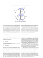
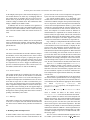
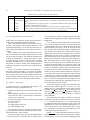
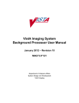
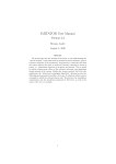
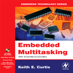
Fig. 1. CARA Reference Model: Main Modes
be closely monitored by a care-giver, who continually adjusts
them depending on the condition of the patient and takes action if a system malfunction occurs. In a battlefield setting,
when one care-giver may be attending many casualties at one
time, medical manpower is often insufficient, and patients
suffer debilitating and often fatal consequences relating to inadequately monitored infusion equipment. CARA represents
a way for automating the work of a care-giver so that the infusion process can function with minimum human intervention.
alarms based upon how critical the associated condition is. If
the power supply to the pump is lost, the control goes to a
backup battery, and a high-priority alarm is sounded.
There are two ways to leave manual mode: the pump may
be turned off, or the care-giver may press the auto-control
mode button to transfer the software to auto-control mode.
This button is only enabled when the pump is in its normal
operative mode (i.e. no error conditions are present); the button that initiates this mode is disabled otherwise.
2.2 Modes of Operation
2.2.3 Auto-Control Mode
The remainder of this section describes how the CARA software achieves the aims just mentioned. The system has three
main modes of operation: Wait mode, Manual mode, and Autocontrol mode. Fig. 1 summarizes how the modes interact;
each mode is described below.
In auto-control mode, CARA assumes two roles: monitoring
the status lines from the pump as well as controlling the infusion rate. In this mode it also supplies diagnostic information
to the care-giver via a display screen in case of exceptions
and maintains a log file of errors, trend data and other data
that would ordinarily be collected by the care-giver. When the
CARA system is in auto-control mode, the care giver plays a
much less active role, and when intervention is required the
software provides suggestions on how to proceed.
At the heart of the CARA system is a PID control algorithm that takes as inputs the current and desired blood
pressures of the patient and, based on the difference between
these, adjusts the voltage driving the infusion pump.
CARA is designed to use up to three sources of blood
pressure data: an arterial line, pulse-wave transmission and a
cuff. Each of these sources can be used as input to the PID
control algorithm. Since these data sources may be simultaneously available the system uses a priority scheme to determine which source to use: an arterial line has highest priority,
followed by pulse-wave transmissions and a cuff, in that order. Thus, if all three sources are available the arterial line is
used as the source of the patient’s blood pressure. If the arterial line source is lost then the pulse-wave source is used, and
if that is also lost, then the cuff source is used.
2.2.1 Wait Mode
The system is in this mode when the pump is off: it performs
no monitoring or pump control.
2.2.2 Manual Mode
The software enters manual mode when the pump is initially
turned on. When the system is in this state the software only
performs monitoring functions; it does not send control signals to the pump, which instead uses default hardware settings set by the care-giver to drive the infusion rate. There are
several anomalous conditions constantly being monitored in
this mode, however: whether there is an air bubble inside the
tube, whether the tube through which fluid is being pumped is
free from leakage, and whether the pump is in proper working
order. There is a 5-second polling cycle for these conditions
along with a specified polling order. An error triggers several
4
Arnab Ray, Rance Cleaveland: Unit Verification: The CARA Experience
For reasons of patient safety the CARA also checks the
integrity of the blood-pressure data it collects. This “corroboration process” involves checking values delivered by either
the arterial or pulse wave to those obtained via the cuff. If the
blood pressures are within an acceptable range of difference,
they are said to be corroborated, else they are are not corroborated. If an available source does not corroborate with the cuff
pressure, then the care-giver is prompted and presented with
the option of overriding and using the uncorroborated source
for the control algorithm. If the care-giver does not want to
override then the next priority source is sought to be corroborated. If that too cannot be corroborated then the software
proceeds using the cuff pressure as the control pressure.
Once a blood-pressure source has been selected the data
it collects is used as input to the PID control algorithm. This
algorithm checks whether the current blood pressure is below
the target value or not. If it is below then it sets an appropriate
pump-control voltage. If the target blood pressure value has
been attained or exceeded then the control voltage is set to
zero, meaning that the infusion ceases.
The care-giver can reset the target blood-pressure value
by entering new input parameters, after which the PID algorithm restarts. But this entering of new values cannot be
done unless all the components are working properly: any
error prevents the care-giver from entering new input parameters.
Re-corroboration of blood pressure sources takes place
every 30 minutes, except that when a new source becomes
available that has a higher priority than the source currently
being used, corroboration of the new source is attempted immediately. Corroboration is also stalled when an override question is pending. Once corroborated, a source will continue to
be used until the next re-corroboration cycle or until a higherpriority source becomes corroborated. All sources are monitored continually, and appropriate action is taken immediately
in case a source is lost. Thus, while a care-giver may have to
wait up to 30 minutes to detect that a corroborated source
has become uncorroborated, an immediate action (alarm and
state change) occurs if a corroborated source is lost.
When the blood pressure of all sources becomes zero,
alarms are sounded, and after waiting for specified periods
of time the software goes back to manual mode. A care-giver
can also return the system to manual mode by pressing the
appropriate button.
3 Modeling Preliminaries
In this section we describe the basic mathematical machinery used in our modeling and analysis of the CARA system.
Before discussing the theory, however, we note that the following characteristics are important in the selection of an appropriate framework.
Real time. The CARA system includes a number of timing
constraints. To be maximally useful, a modeling notation
should include support for these.
Component interaction. The CARA system includes many
components that interact either directly with one another
or with the environment. To model CARA effectively, a
modeling notation needs to support a flexible notion of
component interaction.
Subsystem analysis. To cope with state explosion our unitverification approach requires being able to isolate subsystems within a larger system. An appropriate modeling notation should therefore make it easy to treat system
modules independently.
3.1 Discrete-Time Labeled Transition Systems
The basic semantic framework used in our modeling is discretetime labeled transition systems. To define these we first introduce the following.
Definition 1. A set is a set of visible actions if is is nonempty and does not contain or .
In what follows visible-action sets will correspond to the atomic
interactions users will employ to build system models. The
distinguished elements and correspond to the internal action and clock-tick (or idling) action. For notational convenience, given a visible-action set we define:
We sometimes call the set an action set and as
a controllable-action set (the reason for the latter being that
in many settings, actions in this set can be “controlled” to a
certain extent by a system environment).
Discrete-time labeled transition systems are defined as
follows.
Definition 2. A discrete-time labeled transition system (DTLTS)
is a tuple "!#$%&'()+* where:
1.
2.
3.
4.
!
is a set of states;
is a visible-action set (cf. Def. 1);
,-&/.0!213 14! is the transition relation, and
( )
5 ! is the start state.
A DTLTS 6!#7&'()+* satisfies the maximal-progress prop
(99
erty if for every ( such that ( ,-&8(9 for some (9 , (;,: &8
for any (99 .
A DTLTS <!#$%&=( ) * encodes the operational behavior of
a real-time system. States may be seen as “configurations” the
system may enter, while actions represent interactions with
the system’s environment that can cause state changes. The
transition relation records which state changes may occur:
if <(>?(9* 5 ,-& then a transition from state ( to (9 may
take place whenever action ? is enabled. Generally speaking,
is always enabled; other actions may require “permission”
from the environment in order to be enabled. Also, transitions
except those labeled by are assumed to be instantaneous.
Arnab Ray, Rance Cleaveland: Unit Verification: The CARA Experience
While unrealistic at a certain level, this assumption is mathematically convenient, and realistic systems, in which all transitions “take time”, can be easily modeled. We write ( , & (9
when a system in state ( transitions, via action ? , to state (+9 .
If a DTLTS satisfying the maximal progress property is
in a state in which internal computation is possible, then no
idling (clock ticks) can occur.
DTLTSs model the passage of time and interactions with
a system’s environment. Discrete-time process algebras such
as Temporal CCS [27] enrich the basic theory of DTLTSs
with operators for composing individual DTLTSs into systems that may themselves be interpreted via (global) DTLTSs.
Such languages typically include operators for parallel composition and action scoping, among others. The variant of
Temporal CCS used in this paper, for instance, may be defined as follows. Let be a nonempty set of labels not con5 , where
;
taining and , and fix TCCS is a syntactic operator. Intuitively, contains the set of communication channels, with visible Temporal CCS actions of
the form corresponding to receive actions on port and
corresponding to send actions on port . Then (a subset
of) Temporal CCS is the set of terms defined by the following grammar, where
. and is a maximal-progress
DTLTS whose action set is TCCS .
Intuitively, these constructs may be understood in terms of
the communication actions and units of delay (or idling) they
may engage in. represents the parallel composition of
and . For the composite system to idle, both components must be capable of idling. Non-delay transitions are executed in an interleaved fashion; moreover, if either or
is capable of an output ( ) on a channel that the other is capable of an input on ( ), then a synchronization occurs, with
both processes performing their actions and a resulting: in
this case, no idling is possible until after the is performed.
If '.
then
defines a process in which the channels
or actions in may be thought of as “local”. In other words,
actions involving the channels in the set are prevented from
interacting with the outside environment. The net effect is to
“clip”, or remove, transitions labeled by such actions from
. Other operators, including a hiding operator
that
converts actions whose labels are in into actions, may be
defined in terms of these.
This informal account may be formalized by giving rules
for converting Temporal CCS terms into DTLTSs in the standard Structural Operational Style [29].
Finally, DTLTSs may be minimized by merging semantically equivalent but distinct states. In this paper a specific
equivalence, Milner’s observational equivalence [26], is used
for this purpose. Intuitively, two states in a DTLTS are observationally equivalent if, whenever one is capable of a transition to a new state, then the other is capable of a sequence of
transitions with the same “visible content” to a state that is
observationally equivalent to the new state. To define observational equivalence precisely, we use the following notions.
Definition 3. Let
(>(9 5 ! and ? 5
.
"!#$%&'( ) *
5
be a DTLTS, with
"$ #&%('&) (!* ,-& (+*-(7, (>6(! (9
( (9
( ( ( ( ,-&
( (9
?. ?
. 0/ ?
. =?
? =
: 1 .0!"( 13(! * 5 1
? 5 ( , & (9 (9
( 2 (9
( 6(, 9 & (9 (* 9 5 1
(9 ( 2 (9 6(9 (9 * 5 1
( (
( 43 ( 1 6( ( * 5 1
( (9
( (9
( (9
?
( (9
/
( 8(9
if there exists
such that for
,
.
2.
if there exists
such that
.
3. The visible content, , of is defined by:
and
if
.
4. A relation
is a weak bisimulation if, for every
and
, the following hold.
1.
all
then there exists such that
(a) If
and
.
(b) If
then there exists such that
and
.
5.
and are observationally equivalent, written
if there exists a weak bisimulation with
,
.
Intuitively,
if there is a sequence of internal transitions leading from to , while
if there is a
sequence of transitions, one labeled by and the rest by ,
leading from to . The visible content of is “empty” ( ).
It can be shown that observational equivalence is indeed
an equivalence relation on states, and that observationally
equivalent states in a DTLTS can be merged into single states
without affecting the semantics of the over-all DTLTS.1 It is
also the case that, in the context of the Temporal CCS operators mentioned above, DTLTSs may be freely replaced by
their minimized counterparts without affecting the semantics
of the overall system description. For finite-state DTLTSs,
polynomial-time algorithms for minimizing DTLTSs with respect to observational equivalence have been developed [12,
16,19,28]. This concept will be used later when defining the
minimization procedure for unit verification.
3.2 Model Checking
In automated model-checking approaches to system verification system properties are formulated in a temporal logic; the
model checker then determines whether or not they hold of
a given (finite-state) system description. A given temporallogic formula defines the behavior a system should exhibit as
it executes; as such, temporal logic extends more familiar notations such as the propositional calculus with operators enabling one to describe how a system behaves as time passes.
In this work we use a (very small) subset of the modal
mu-calculus [21], a temporal logic for describing properties
of (discrete-time) labeled transition systems. The syntax of
the fragment is described as follows, where is a visibleaction set (cf. Def. 1).
5 >6?* 5 76?98 5 <"?* 5 6?:8 5
tt ff
1
More precisely, the notion of observational equivalence can be lifted
to a relation between DTLTSs, rather than just between states in the same
DTLTS. It can then be shown that a DTLTS is observationally equivalent to
its minimized counterpart.
6
Arnab Ray, Rance Cleaveland: Unit Verification: The CARA Experience
:/
. The full mu-calculus contains other opHere ? 5
erators, including conjunction, disjunction and recursion constructs; a full account may be found in [21].
These formulas are interpreted with respect states in a
given DTLTS. The formulas tt and ff represent the constants
“true” and “false” and hold of all, respectively no, states.
The remaining operators are modal in that they refer to the
transition behavior of a state. In particular, a state ( satisfies
"?*$ if there is another state (9 such that ( (9 and
(9 satisfies , while ( satisfies ? if every (9 such that
( (9 satisfies . The operators 6?<* and ? are
similar except that they treat clock ticks as being analogous
to -transitions. More precisely, we define the following.
5 5
5
Definition 4. Let
(>( 9 5 ! and ? 5 .
"!#$%,-& ( ) *
be a DTLTS, with
+
#0% #0 )
) "
(9 if there exists ( ( > ( (9 ? 6? such that ( -, & ( ( ,-& ( and
? 5 + for all .
2. (
(9 if there exists ( ( such that ( ( , & ( (9 .
So (
(9 if there is a sequence of , and , transitions
(9 if there is a sequence of
leading from ( to (9 , while (
transitions, one labeled by ? and the rest either by or ,
leading from ( to (9 .
We can now define "?*$ and ? more precisely. A
(9 and
state ( satisfies 6?<*$ if there is an (9 such that (
(9 satisfies . Dually, ( satisfies ? if every (9 reachable
via a transition from ( satisfies .
The operators *$ , , * and are not
1.
(
6 98
6 98 5
* and
6 98
5
5
68
6 98 5 5
5 68
primitive mu-calculus operators, but they can be encoded using the primitive operators.
if is a DTLTS whose
In what follows we write
start state satisfies .
5
3.3 The Concurrency Workbench of the New Century
In the case study we use the Concurrency Workbench of the
New Century (CWB-NC) [12–14] as the verification engine
for conducting our analysis of CARA.
The CWB-NC supports several different types of verification, including mu-calculus modeling checking, various kinds
of refinement checking, and several types of semantic equivalence checking. The tool also includes routines for minimizing systems with respect to different semantic equivalences,
including observational equivalence.
The design of the CWB-NC makes it relatively easy to
retarget it to different design languages. The Process Algebra
Compiler (PAC) tool [11,14] provides support for adapting
the design language processed by the CWB-NC. In the case
of CARA, we started with a basic Temporal CCS CWB-NC
front end included in the release of the tool and modified it
slightly to include constructs, such as the disabling construct
from LOTOS [8], that simplified the modeling of the system.
4 A CARA Reference Model
In order to develop formal models of CARA suitable for analysis by the CWB-NC we first define a reference model for the
system. This model has two components.
Modes. A high-level rendering of the modes the software
can be in. CARA’s modes are described in Section 2.2
and Fig. 1.
Architecture. A decomposition of the system into communicating components, each of which is modeled operationally using finite-state machines.
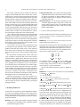
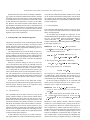
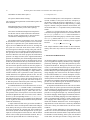
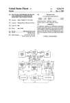
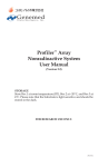
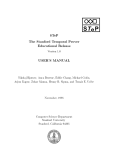
The architectural component of the reference model is given
in Fig. 2, which also provides an abbreviated description of
the interactions between the modules in the architecture. In
this diagram ovals represent system components, while circles constitute environment components.
The remainder of this section provides a brief description of each component in the CARA architecture. Before
giving this, however, we first note that none of the CARA
documents explicate the system architecture; we have instead
devised one based on the rationale that there should be one
module for each physical component or major control unit
of the system. Care was also taken to minimize the communication interfaces between components so that components
were as independent of each other as possible. The interprocess communication, though not explicitly stated in the design documents, was assumed to be via synchronous message
passing or through shared variables.
4.1 Alarm
This Alarm module is modeled as a system that takes in two
types of error conditions, HighAlarm or LowAlarm. Depending on what type of an alarm it is, the alarm determines its
“silencing time,” that is, the amount of time that it will be silenced when a care-giver presses the Silence Alarm button.
Note that the Alarm’s audible and visible indicators are completely deactivated only when all the conditions that caused
an alarm to be raised have been fixed.
4.2 Alarm Control
The Alarm module deals with the hardware component of the
visual and audible alarms. The decision as to when the alarm
module is to be set or reset is handled by the Alarm Control. As the name suggests, this is the controller process for
the Alarm. It takes as its input all possible alarm conditions
from all possible modules that can raise an alarm and then,
based on its internal logic, decides whether to raise a high
or a low alarm. This architecture makes it possible to make
the alarm-control logic independent of the actual hardware
modeling of the alarm. Thus, even if in the future the logic
for alarm-control changes, only this part of the system needs
to be changed. This paradigm of separating the physical device from its controller is a principle we have followed in the
entire reference-model design.
Arnab Ray, Rance Cleaveland: Unit Verification: The CARA Experience
DISPLAY
Button
User Input
Activation
/Deactivation
DISPLAY
CONTROL
ALARM
High/Low Alarm
Set and Reset
CONTROL
User Input Setpoint
Pump
Errors
PRESSURE
CONTROL
Value
PULSE WAVE
CONTROL
Value
Poll
Pressure
Errors
ARTERIAL
SOURCE
PULSE WAVE
SOURCE
Value
CUFF
CONTROL
Controlling
Pressure Value
Value
CUFF
SOURCE
Poll
PID LOOP
Mode change
Value
Poll
Value
User Input
Corroboration
Question
ALARM
ARTERIAL
CONTROL
7
MODE
CONTROL
Check
For Errors
Fluid Infusion Rate
PUMP
CONTROL
Status info
Set Fluid
Infusion Rate
PUMP
Fig. 2. CARA Reference Model: System Architecture and Module Interaction.
4.3 Pump
4.5 Display
The Pump module is the physical device that pumps fluids
into the patient. In our model the pump is modeled as a black
box: since the internal workings of the pump is outside the
scope of the design documents that were supplied, the pump
is taken to be a monolithic entity which only supplies data on
the pump-status lines. In other words, the pump is treated as
a source of data to the rest of the system, and nothing else.
The Display module consists of the interface presented to the
care-giver in order to control the CARA system. It comprises
buttons that enable the care-giver to make mode changes, input new target blood-pressure values, or resolve corroboration questions regarding whether or not an uncorroborated
blood pressure is to be overridden.
4.6 Display Control
4.4 Pump Control
The pump status is communicated to CARA in two ways: either through interrupts (continuity, occlusion, power) or through
polling (air, emf, impedance). The Pump Control’s functions
are to monitor the interrupts continually, so that action may be
taken when they come, and to monitor the poll lines according to a given frequency. The Pump Control is also responsible for determining when to raise an alarm and for conducting subsidiary checks when an error occurs (e.g. whenever an
emf-error occurs the impedance is also checked).
The Pump Control also takes input from the PID Algorithm and changes the hardware settings of the pump so that it
can pump at the requisite rate. The control outputs are treated
as “visible actions” that are offered to the environment of the
CARA model. This is because we do not model the physical
workings of the Pump and thus cannot simulate Pump behavior in response to a given control signal.
Display buttons are not always available to a care-giver. For
example, the system can only enter auto-control mode when
there are no error conditions in the system. Hence, if there is
an error anywhere in the system the Start Auto-control button should be “grayed out.” Similarly there is a priority to
the input windows that are offered to the user when multiple user inputs are needed. For example, a corroboration window would have a higher priority than the new input parameter window. Maintaining the priority information and suitably
activating/de-activating buttons is the job of the Display Control.
4.7 Mode Control
There are two ways of affecting a change in mode within
CARA. One is when the user engages in explicit button presses
8
Arnab Ray, Rance Cleaveland: Unit Verification: The CARA Experience
on the Display. This aspect is dealt with in the Display Control module. But there are other ways of changing mode. In
auto-control mode, for example, there are several error conditions which, if persistent for specific periods of time, necessitate a change to manual mode. This autonomous mode
change is handled by the Mode Control.
In addition, there are error conditions to be signaled if a
required blood-pressure range is not attained within a specific
time after auto-control initiation. Mode Control also keeps
track of the time instant at which auto-control mode was entered.
4.8 Sources
There three different Sources modules, one for each potential
source of blood-pressure readings: Arterial, Pulse-Wave and
Cuff. These are basically stub processes that model potential
patient behavior.
4.9 Source Control
The Source Control modules are also three different, independent modules, one for each potential source. Source Control
primarily deals with the frequency of polling the respective
source being controlled. It also deals with the issue of when
to signal errors or, more specifically, how many poll failures
are required before an error is flagged. It additionally supplies the eventual blood-pressure value to the Pressure Control module, and this value is used for the PID loop.
4.10 Pressure Control
This control module may be considered to be the most complex module in the system. Its first function is to determine
which blood-pressure source to use as the controlling source.
It compares blood pressures from different sources to corroborate them. It keeps track of when to corroborate the pressure sources. If a blood-pressure source becomes uncorroborated, it signals the Display module to ask the override question and takes action according to the user supplied input. If
a higher priority blood pressure than the current controlling
blood pressure starts reporting valid values and no override is
pending, it immediately takes action.
4.11 PID Loop
This module compares the controlling blood pressure value
to the user-set set-point value and controls the fluid-infusion
rate on the basis of whether the set-point has been attained or
not.
5 Modeling CARA in Temporal CCS
To model CARA so that it can be analyzed in the CWB-NC,
we first must encode the reference model described in the
previous sections in the version of Temporal CCS supported
by the tool. This section describes this encoding.
Our general modeling strategy is to “implement” each
module in the reference model as a DTLTS and then interconnect these DTLTSs using the other operators from Temporal CCS. In practice, because the Temporal CCS model must
concern itself with implementation details (e.g. how shared
variables are represented) that the reference model does not,
we used several DTLTSs for each reference module. For instance, the Temporal CCS model contains 23 different individual DTLTSs to implement the 23 shared variables (21
boolean-valued, one eight-valued, and one nine-valued) used
to exchange data between the other modules. Table 1 lists the
DTLTSs in our Temporal CCS model, together with a brief
discussion of what behavior each DTLTS is responsible for.
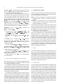
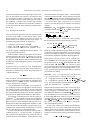
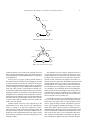
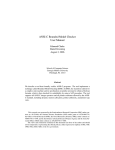
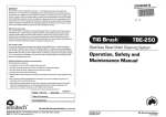
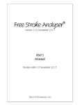
Figs. 3 and 4 give example DTLTSs taken from our model.
In the case of the CuffControl module, what is shown
is the minimized version of the DTLTS; to simplify the diagram, we have also omitted the clock-tick transitions (every
state has a clock-tick transition back to itself in this case).
This DTLTS encodes the following behavior. When instructed
to take a cuff reading, the cuff control executes an action to
get a cuff value. If the value is valid, then this is recorded, and
any alarm due to a lost cuff is disabled. If the value is invalid,
then another cuff reading is attempted. If the second value is
valid, then the previous sequence of events is repeated; otherwise, the cuff is determined to be invalid, and an alarm raised.
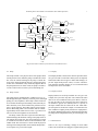
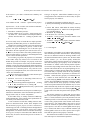
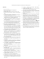
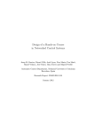
The BPMonitor DTLTS is larger than CuffControl,
since the module it models is more complex. For clarity a
number of transitions, including clock-tick transitions that
lead back to the state from which they originate, have been
left out. In addition, sequences of clock-tick transitions have
been collapsed into single transitions labeled by the number
of clock ticks.
The Temporal CCS implementation of the Alarm module consists of three separate DTLTSs: one for a high-priority
alarm, one for a low-priority alarm, and a controller that activates and deactivates the alarms as appropriate. These DTLTSs
are
named
HighRinger,
LowRinger,
and
AlarmController, respectively. The Temporal CCS expression Alarm is then:
HighRinger LowRinger AlarmController
where
contains the labels of the actions used by
AlarmController to activate and deactivate the alarms.
Table 2 contains size data for each of the Temporal CCS
DTLTSs given above. The second and third columns list the
number of states and transitions for each of these DTLTSs;
the next two give the sizes after the system have been minimized with respect to observational equivalence. The final
column gives the amount of CPU time needed to perform the
minimization within the CWB-NC. All the experiments were
carried out on a Sun workstation running Solaris 2.6, with a
360 MHz UltraSparc II processor, 256 MB of RAM, and 1
GB of swap space.
The sizes of these individual DTLTSs imply that the entire CARA system contains in excess of states.
" Arnab Ray, Rance Cleaveland: Unit Verification: The CARA Experience
9
LostCuffAlarmRaise
TakeCuff
GetCuffValue
InvalidValue
ValidValue
InvalidCuff
GetCuffValue
InvalidValue
ValidCuff
LostCuffAlarmStop
ValidValue
Fig. 3. The CuffControl Module.
’BPAlarm
’Takecuff
’ModeIsManual
InValidCuff
ValidCuff
No
’Override?
Source Change
Source Change
InValidAline
Yes
ValidAline
Aline
UnCorroborated
ValidPWave
InValidPWave
Pwave
UnCorroborated
’Override?
’Override?
No
ValidAline
InValidAline
Yes
Yes
Aline
Corroborated
No
Pwave
Corroborated
Source Change
InValidPWave
ValidPWave
Pwave
Corroborated
Pwave
UnCorroborated
’Takecuff
60s
BP<6060<BP<70
120s
70<BP<90
BP>90
300s
Fig. 4. The BPMonitor Module. For clarity, some transitions have been omitted. White states have a transition to the start state upon the receipt of a
corroboration signal; black states do not.
10
Arnab Ray, Rance Cleaveland: Unit Verification: The CARA Experience
Table 1. Modules in the Temporal CCS Model of CARA.
Module
Alarm
CorrobControl
AlarmControl
AirChecker
EmfChecker
ContinuityChecker
OcclusionChecker
PumpPowerChecker
Display
OverrideControl
ModeControl
PressureControl
PIDControl
PWaveControl
AlineControl
CuffControl
BPMonitor
BPDropMonitor
Misc. variables
Purpose
Raises alarms
Controls when corroboration takes place
Parses the different errors and signals the Alarm
Checks the Air
Checks the Emf
Checks Continuity
Checks Occlusion
Checks Power
Handles user input and window priorities
Controls the Override question
Controls when mode change takes place
Checks to see if desired pressure is attained within a certain time after infusion started
Handles the PID Loop
Controls the acquisition of pulse wave
Controls the acquisition of arterial line
Controls the acquisition of cuff when all other sources are lost
Controls priority among different pressure sources and determines the controlling pressure source
Checks to see if there is a blood pressure drop after attainment of steady value
Shared variables used for inter-module communication
Table 2. Size Data for Modules in Table 1.
Module
Alarm
CorrobControl
AlarmControl
AirChecker
EmfChecker
ContinuityChecker
OcclusionChecker
PumpPowerChecker
Display
OverrideControl
ModeControl
PressureControl
PIDControl
PWaveControl
AlineControl
CuffControl
BPMonitor
BPDropMonitor
Misc. variables
"
Original Size
States
Transitions
104
452
1,805
3,619
6
66
893
2,504
555
1,477
6
18
6
18
6
18
68
343
9
54
912
5,172
4
11
1,206
1,214
163
209
163
209
11
26
646
748
18
66
Even after the components are minimized, the resulting system still has over states.
Minimized size
States
Transitions
19
76
1,804
3,613
6
66
225
606
345
968
4
12
4
12
4
12
44
205
5
30
606
3,028
4
11
1,205
1,211
153
180
153
180
9
20
627
683
13
41
Minimization
Time (sec.)
0.600
3.030
0.820
2.440
1.560
0.010
0.010
0.010
0.360
0.070
5.730
0.000
0.830
0.180
0.120
0.010
0.540
0.050
N/A
the requirements and simulating and refining the model under development. It should also be noted that requirements
expressed in a natural language like English are imprecise,
and
often reasonable assumptions have to be made with reModeling Effort
spect to the constructed models. And Although this modelconstruction phase is laborious and frequently frustrating, its
The tables in the previous section convey information about
benefit cannot be overemphasized. The exercise of formally
the computational effort needed to minimize the models we
encoding a system brings to the fore many ambiguities that
developed. However, the effort expended in a verification project
otherwise would slip into the system design; this process of
is not only due to the time elapsed between “pushing the butmodel elicitation, if fed back to the requirements team, can
ton” and “getting a result”, but also the manpower needed
typically also lead to better and more precise encodings of
to construct the models in the first place. The work involved
requirements.
in model creation is an iterative process involving inspecting
Arnab Ray, Rance Cleaveland: Unit Verification: The CARA Experience
Based on the above observations, evaluating a methodology requires an account the human effort needed to construct
the models. In the case of this project, it took an approximate
of 60 man-hours to settle on a reference model of the CARA
system and about ten man-hours to encode it in the CWBNC. However, the reference-model creation and the encoding/validation of the model went on side-by-side and involved
many iterations. It should also be noted that the effort would
have been significantly less if we had been able to interact
more with the actual system designers in order to clarify ambiguities in the system requirements.
6 Verifying CARA: The Unit-Based Approach
The previous section gave a sense of our Temporal CCS model
of CARA. In this section we describe our efforts to check
specific properties of the model. These properties were extracted from the CARA requirements documents given to us
by WRAIR researchers [3–5].
Our initial intention was to take the model of Section 5,
translate requirements into the modal mu-calculus [21], and
use the CWB-NC’s model checker to check which properties
held and which did not. This approach proved untenable, owing to the large size of the model, even after the individual
components were minimized.
Instead, we pursued a strategy we refer to as unit verification, and which was also used in [15], although it was not
referred to by this name in that paper. Such an approach is
feasible when requirements are given as scenarios (“whenever a certain behavior is observed, take these actions”) that
involve small subsets of the over-all components in the system. The essential idea is to encode the relevant scenario as
a process that interacts with the components in question and
then check whether the outcome of the scenario is “successful” or not.
In the rest of this section we first define unit verification more precisely and talk about the properties that can be
checked using it. We then report on our experiences using
unit verification to study the CARA model.
6.1 Unit Verification
Unit verification derives its name from unit testing. In unit
testing, software modules are first tested in isolation before
being assembled into full systems. In order to test a module that may, in the final system, not have an interface to the
external environment, one typically constructs a test harness
that drives the execution of the software under test. Unit testing is frequently used in software projects because it gives
engineers an ability to detect bugs at the module level, when
they are easier to diagnose and fix. For unit testing to work,
of course, one must have module-level requirements at hand
so that test results can be analyzed.
In unit verification, the set-up is very similar to unit testing: single modules are verified in isolation using “harnesses”
11
to provide the stimuli that the other modules in the system
(or the external environment) would generate once the module is deployed. As with unit testing, this approach requires
the presence module-level requirements so that results can be
correctly interpreted.
6.1.1 Trace Properties
Unit verification deals primarily with trace properties: properties of system executions. In this section we sketch a basic
theory of such properties.
As executions may be thought of as sequences, we use
standard mathematical operations on sequences in what follows: if is a set, then is the set of sequences whose elements come from , if 9 are sequences then 9 is the
sequence obtained by concatenating them in the given order,
is the empty sequence, etc.
/
"!#$%,-& ()* be a DTLTS.
Let (>(9 5 ! be states and 5 be a sequence of
(non- ) transition labels. Then
( (9 in Def. 3(1), or ( ( 9 if and
? 9 and ( 99 5 ! ( ( 99 ( 9 .
The language, '( , of ( 5 ! is defined by:
=
( ' 5 ( ( 9 some ( 9 5 ! Definition 5. Let
1.
2.
0/
3. The language,
of
is defined by:
'() +
The language of a state in a DTLTS contains the sequences
of visible actions / clock ticks that a user can observe as execution of the DTLTS proceeds from the state. The language
of the DTLTS is just the language of the start state.
In this case study the properties we are concerned with
involve system executions and come in two varieties: safety
and quasi-liveness. These are defined as follows.
Definition 6. Let
"!#$%,-& ( ) be a DTLTS.
1. A safety or quasi-liveness property over is any subset
of .
2.
satisfies safety property if and only if .
.
3.
satisfies quasi-liveness
property iff for every (
such that ( ) ( , there exists 9 5 '( such that
9 5 .
Intuitively, a safety property contains “allowed” execution
sequences; a system satisfies such a property if all the system’s executions are allowed. A quasi-liveness property is
more complicated: it contains sequences that a system, regardless of the current execution it has just performed, should
be able to “complete”. We call these properties quasi-liveness
because the definition of satisfaction does not require that
such “complete-able” executions actually be completed, only
that the system always be capable of doing so. At first blush,
12
Arnab Ray, Rance Cleaveland: Unit Verification: The CARA Experience
this requirement may not seem strong enough to ensure “liveness” in the tradition sense. However, our intuition is that,
if a quasi-liveness property is satisfied by a system, then in
any “reasonable” run-time setting employing some kind of
fair scheduling, a “complete-able” execution will eventually
be completed. These definitions are inspired by, but differ in
several respect from, the classic definitions of safety and liveness in [6].
6.1.2 Defining Unit Verification
The unit verification approach we advocate in this paper may
be used to check whether a system satisfies safety / quasiliveness properties as defined in the previous section. The
method consists of the following general steps, where
is
the module being analyzed and is the property.
6 8 6 8
6 8
68
1. Construct a verification harness
.
into
, yielding a new system
2. Plug
3. Apply a check to
to see if
satisfies
6 8
The checks applied to
depend on whether
is a
safety or quasi-liveness property.
In the remainder of this section we flesh out the unit verification approach in the context of Temporal CCS. We define what verification harnesses
are and the checks that
are applied on
. We also discuss optimizations to the
procedure that can be undertaken to improve (often greatly)
performance.
68
46 8
Verification Harnesses in Temporal CCS. Verification harnesses are intended to “focus attention” on interesting execution paths in a module being verified. The general form of a
verification harness is:
6 8 where is the set of all communication labels,
is a (deterministic) Temporal CCS expression that we sometimes call a
verification process, and is the “hole” into which the module to be verified is to be “plugged”.
As a practical matter, in our CARA work we did not derive verification processes from properties; instead, based on
our reading of system requirements we directly constructed
the
components of our test harnesses and used them as
our representations of properties. We therefore explain how
properties may be extracted from DTLTSs in what follows.
In our setting, verification processes draw their visible actions from TCCS (the Temporal CCS action set introduced in
Section 3.1) augmented with two special actions, good and
bad. The latter are used to determine what properties a verification process defines. Recalling that the semantics of Temporal CCS specifies how Temporal CCS expressions may be
“compiled” into single DTLTSs, in what follows we assume
that our verification processes are single DTLTSs.
In order to characterize the properties associated with a
is intended to
verification process , we first note that
run in parallel with the module being verified. In order to
guide the behavior of the module, must synchronize with
68
Definition 7. Let 5 TCCS
be a sequence of externally
controllable actions. Then 5 TCCS
is defined inducTCCS
tively as follows, where ? 5
.
1.
2.
/? / 9 A verification process defines both a safety property,
, and a quasi-liveness property, , as follows.
? 9 , where 3
and
.
5 : bad 5 5 good 5 .
or not.
the modules actions, meaning that when wants the module
to perform an input action ? , must perform the corresponding output ? . In general, then, since module properties refer to
the actions in the module, to associate a module property with
we need to reverse input / output roles in ’s execution
sequences. To make this precise we introduce the following
notation.
Intuitively, if bad is possible as the next action in an execution then the execution, and all possible ways of extending it,
are removed from . Similarly, action sequences leading
to the enabling of good are included in the property .
68
46 8
Defining Safety and Quasi-Liveness Checks. From the structure of
one can see that the only actions that
can perform for any
are + good and bad. This is due
to the fact that
, and the
opera tor prevents all but these actions from being performed. This
fact greatly simplifies the task of checking whether or not a
safety / quasi-liveness property encoded within a verification
process holds of a module.
6 8
Theorem 1. Let
be a Temporal CCS system model and
be a verification process. Then the following hold.
1.
2.
satisfies satisfies if and only if if and only if 9: 6 6 / 8 8 bad
Proof. Follows immediately from the definitions of ,
and . The determinacy of is important.
ff
good *$ tt
,
6 8
: This theorem says that the correct “check” for the safety property encoded in a verification process is to see whether or
not the “plugged-in” verification harness, , forever disables the bad action: formula bad ff holds exactly when there are no execution sequences consisting of ’s,
’s and a single bad action. Likewise, to check if ’s liveness
property holds of , it suffices to check that sat
isfies good *$ tt: if so, then regardless of what
does, there is still a possibility of evolving to a
state in which good is enabled.
In some cases, it may be more natural to “look for bugs”
rather than to try to prove the nonexistence of bugs. This
might be the case if, for example, one strongly suspects erroneous behavior. To determine if a module violates a verification process’s safety property, one may perform the following
check:
' bad * tt
6/ 8
: Arnab Ray, Rance Cleaveland: Unit Verification: The CARA Experience
If the answer is “yes” then a violation exists. Similarly, one
may check
9 /*$:6 8 good
to test whether or not
violates
Putting It All Together. What follows summarizes our general approach to unit verification. To check a safety or quasiliveness property of a module :
ff
Optimizations. So far our basic unit verification methodology consists of the following steps.
1. Formulate a verification process .
2. To check whether or not ’s safety / quasi-liveness property holds of , check whether or not simple modal mucalculus formulas hold of
“running in parallel with”
.
In our case study work, we found that two simple optimizations greatly facilitated this process; we describe these here.
Minimization. Checking whether or not a mu-calculus property holds of a system requires, in general, a search of the
system’s state space. Reducing the size of this state space
thus reduces the time required by this search. In the case of
, one way to reduce states in the parallel composition is to reduce states in and
by minimizing them with
respect to observational equivalence.
Action Hiding. In general, the properties we confronted
in the CARA study only focused on a few actions in the
module being tested. For example, in a property of the form
“whenever a blood-pressure source fails, an alarm should be
sounded”, actions not related to detecting failure and raising
an alarm are unimportant. Mathematically, this is reflected in
the structure of a verification process: every state has a selfloop for every unimportant action, since such actions do not
“affect” the verification result.
This observation can be exploited to reduce the state space
of even further as follows.
: : ,
'9- 9
1. Partition
into a set of “interesting” labels and a set
of “uninteresting labels.”
2. Hide actions involving uninteresting labels in , creating
(and likewise for , creating 9 ).
3. Minimize
and 9 and perform the safety / quasi-liveness
check on 9 '9 .
: Hiding actions turns them into ’s; this process enhances possibilities for minimization, since observational equivalence is
largely sensitive only to “visible” computation.
In the CARA study, we usually constructed 9 directly,
without minimizing; so the benefits of this optimization accrue mostly in the construction of 9 .
A note of caution is in order here. Hiding actions in Temporal CCS turns them into actions. Since Temporal CCS
has the maximal progress property (cf. Def. 2 in Section 3),
introducing cycles of ’s via hiding can cause timing behavior
to be suppressed (a -cycle can cause “time to stop”). When
hiding actions, care must be taken not introduce such loops,
or divergences, as they are often called. The CWB-NC model
checker may be used to check for the presence or absence of
divergences.
1. Formulate an appropriate verification process .
2. Identify the interesting ( ) and uninteresting ( ) labels in
.
3. Form 9
, which hides the actions involving
uninteresting labels in . Make sure no divergent behavior is introduced into 9 .
4. Minimize 9 , yielding '99 .
5. Do the same on if necessary, yielding 9 9 .
6. To check ’s safety property: determine whether or not
9 9
'99 bad ff.
7. To check ’s quasi-liveness property: determine whether
good * tt.
or not 9 9 '9 9 ’s quasi-liveness property.
13
: 6 8
: 6 / 8
6.1.3 Tool Support.
The CWB-NC tool includes several routines that support the
unit verification procedure described above. Primary among
these are two different routines for checking whether or not
mu-calculus formulas hold of systems. One, the basic model
checker, returns a “yes / no” answer quickly. Another, the
search utility, searches from the start state of a system for another state satisfying a given property: if one is found, then
the simulator is “loaded” with a shortest-possible sequence
of execution steps leading from the start state to the state in
question. This enables the user to step through the given execution sequence to examine how the found state was reached.
The search utility is especially useful in the “bug searching”
procedure mentioned earlier. In particular, to determine if a
module violates the safety property of verification process
, it suffices to search from the start state of for a state satisfying bad * tt (a mu-calculus formula holding
of states from which bad is immediately enabled). If such a
state is found, then the safety property is violated, and the
execution sequence loaded into the simulator may be examined to determine why. In the case of quasi-liveness, the same
process may be searched for a state satisfying good ff:
if such a state exists then the quasi-liveness property is violated.
The tool also contains a sort utility that, given a Temporal CCS system description, returns all the externally controllable (i.e. non- ) actions the system can performed. The sort
command provides a convenient utility for checking whether
or not a safety property holds: check whether or not the harnessed process’s sort contains bad. It also may be used to
check for violations of quasi-liveness properties: if the harnessed process’s sort does not contain good, then the property is violated. The latter is only a sufficient condition: just
because good is in the sort of such a process does not guarantee that the quasi-liveness property is satisfied.
The CWB-NC also includes a routine for minimizing systems with respect to observational equivalence.
6 8
14
Arnab Ray, Rance Cleaveland: Unit Verification: The CARA Experience
Table 3. Properties Checked on CARA Using Unit Verification.
Number
1
2
Type
Safety
Quasi-liveness
3
Safety
4
5
6
Safety
Safety
Safety
Property
“Two successive Emf checks occur no more than five seconds apart.”
“If an override question is asked and then not answered, a corroboration cycle will never start
again.”
“The alarm module reacts properly to errors, i.e. a high-alarm condition results in a high ring and a
low-alarm condition results in a low ring.”
“When an override question is pending, the system cannot take a new input parameter.”
“When an alarm condition is present, the system cannot move from manual to auto-control mode.”
“When the system is in an error state, no new input parameter will be accepted.”
6.2 Analyzing CARA Using Unit Verification
In this section, we concentrate on half a dozen properties of
CARA that we investigated using unit verification.
Table 3 summarizes the properties discussed in more detail below. The properties were all derived from the CARA
requirements documents [3–5]. In each case, the property focuses on the localized behavior of one, and in one case two,
modules.
Table 4 summarizes the results obtained using unit verification. The data reported includes the property, the size of the
relevant “harnessed module”, the CWB-NC command used
to check the relevant safety / quasi-liveness property (“chk”
for model checking, “search” for the state-space searching
procedure described above), the outcome of the check, and
the seconds of CPU time needed. The workstation used to
conduct the experiments is the same as the one mentioned in
Section 5.
As can be seen from the reported results, Properties 1
and 2 fail to hold of the model; we view these as products
of inconsistencies in the requirements. In the rest of this section, we explain the sources of these anomalies and describe
in more detail the verification processes used to uncover the
problems. We also give more detail on the other properties.
6.3 Property 1: Amok Time
To explain the source of the problem with Property 1, we
mention some design requirements from [5].
1. Impedance and back Emf values are polled values. (vide
Q66)
2. When a polling request fails, retry two more times at onesecond intervals. Only if three attempts fail should an
alarm be raised. (vide Q74)
3. The following sequence of events must occur at five-second
intervals. (vide Q70)
(a) Check Emf
(b) Update display of flow rate
(c) Check impedance value
We claim that these three requirements are not compatible: if Requirements 1 and 2 are satisfied, then there is a case
when Requirement 3 will be violated.
To justify our claim, we first give an informal argument as
to why there would be a violation. Then we formally prove
it by constructing a suitable verification process that, when
combined with the appropriate module, is capable of emitting
a bad action.
Let us consider the following scenario. An Emf check
starts. The first reading at the end of one second (since Emf
is a polled signal) is an error. By Requirement 2 it is checked
again and again gets an error. (So far two seconds of time
have elapsed.) Then on the third attempt, a valid Emf reading is obtained (time elapsed: three seconds). Then, based on
Requirement 3b the flow rate is adjusted. Since no data for
updating flow rates was given, we assume it is instantaneous.
Then the impedance check is performed. Since that too is a
polled value like the Emf, it follows the same discipline of
three bad readings before an error is flagged. Like the Emf,
let the first two readings, at a one-second intervals each, give
errors and the third reading give a good value. So the time
elapsed is six seconds. So even if an Emf check starts at that
second, six seconds have elapsed since the initiation of the
last Emf check. This violates Requirement 3, which states
that at most five seconds can have elapsed. The sequence of
events described is valid, and a sequence in which an alarm
is not raised. So it cannot be justified as an error run which
could be assumed to violate some other constraints. What we
have is a valid run violating the constraints imposed by the
specifications by making the time elapsed between two successive Emf checks to be six seconds.
To show this formally, we apply unit verification to the
relevant module, which in this case is EmfChecker. The
transitions we are concerned with relate to those involving
erroneous (Emf 0) and valid (Emf 1) Emf readings and erroneous (Imp 0) and valid (Imp 1) impedance readings. All
other transitions in EmfChecker are hidden, i.e. converted
into -transitions.
The verification process itself is a Temporal CCS process
constructed using the two DTLTSs given in Fig. 5. DTLTS
Timer awaits the enabling of its start action (idling loops
are omitted) and then counts down five seconds. At any time
during this five seconds, if it is capable of performing its end
action, then the timer is reset. If time expires and end happens, then bad is performed. This timer captures the fivesecond upper bound in Requirement 3.
DTLTS Test, on the other hand, starts the timer by performing start and then engages in the sequence of actions
described above: two successive erroneous reading of the Emf
Arnab Ray, Rance Cleaveland: Unit Verification: The CARA Experience
15
Table 4. Results of Properties Checked on CARA.
Property
Number
1
2
3
4
5
6
Harness size
States Transitions
101
127
5,423
7,247
65
107
32
72
85
757
18
32
CWB-NC
Command
search
chk
chk
chk
chk
chk
Result
False
False
True
True
True
True
Time
(sec.)
0.280
17.820
0.190
0.210
3.440
0.070
start
1
start
Emf_0
end
1
5
Emf_0
1
Emf_1
end
end
1
Imp_0
bad
1
Imp_0
1
Timer
Imp_1
Test
Fig. 5. DTLTSs Timer and Test Used in Verification Process for Property 1.
followed by a valid one, and likewise for the impedance. At
the end, it stops the timer by emitting end.
The whole verification process is then given by the Temporal CCS expression
Timer Test
start end The restriction operator ensures that only Test can start and
stop Timer. The net effect of this process is to attempt to perform a valid six-second execution sequence on EmfChecker.
The results in Table 4 vindicates our intuitions: Requirement 3 is violated.
As a final observation, we note that this use of unit verification may be seen as a formalized counterpart to debugging.
In this case we informally observed what appeared to be a
problem and then constructed a verification harness that exposed it.
6.4 Property 2: Locked in Life
As in the previous property, we first give an intuitive formulation of the problem. The first relevant requirement for this
property is given as Q118 in [5], where the following question is asked and answered.
What should be done if the 30-minute timer activities
are pending due to an unanswered override question,
16
Arnab Ray, Rance Cleaveland: Unit Verification: The CARA Experience
and another 30-minute timer expires ?
6.5 Properties 3–6
The system should continue waiting.
In contrast with Properties 1 and 2, Properties 3–6 hold of the
relevant “modules” of the system. In the case of Property 3,
the module to which the property is applicable is Alarm (cf.
Table 1). The verification process is depicted in Fig. 7 (idling
loops are omitted). Using the CWB-NC model checker, one
can determine that Alarm responds correctly to alarm-raising
stimuli.
Property 5 is of interest because the “unit” to which unit
verification is being applied consists of two modules from Table 1: Display and ModeControl. This is because the requirement from which the property is drawn refers to actions
in Display (alarms) and ModeControl (mode switches).
The unit to which the relevant verification process is applied
has form
Display ModeControl
The second relevant requirement is mentioned in Q109 in the
same document:
What should be done to current corroboration attempts
if another higher priority source starts reporting?
The current corroboration attempts must complete before the new sources will be corroborated. This means
that the override question must be answered before
corroboration is attempted for any new source.
The problem with this is immediately clear: what would
be the situation if the override question is never answered?
By the above requirement, the system should continue waiting for successive -minute intervals forever, meaning that
the system is in a live-lock. Even when a source comes up,
the system ignores it and keeps waiting (vide Q109). The implications are severe. For example, suppose that the cuff pressure goes down, the override question is asked, and it is not
answered. When the cuff comes up again, the corroboration
question is no longer relevant (as the original corroboration
question was initiated by the cuff becoming invalid). But the
question, despite being irrelevant, is still being asked. On top
of that, the system does not take any action based on the fact
that the cuff has come up and stops corroboration until the irrelevant override question is answered. Since the purpose of
this system is to operate with minimal manual intervention,
it seems a reasonable assumption that there might be scenarios (e.g. a single care-giver attending to a large number of
wounded soldiers) when a particular override question may
remain unanswered for significant periods of time. For that
entire duration, all corroboration efforts will stop and the system will take no steps to resolve the override question. Even
if the source comes up, the system will not be receptive to
it. Thus the pressure-control subsystem would stop working
until someone answers the override question.
To establish that this live-lock can indeed occur, we focus
on the CorrobControl module of Table 1, which handles
corroboration issues. The associated verification process is
given as a single DTLTS in Fig. 6, which “asks” the override question, awaits a blood-pressure reset action, and then
performs the good action. The reset action is never enabled,
however, by the corresponding action in CorrobControl,
and thus no good action is every performed by the harnessed
process. Again, our intuitions are confirmed: the requirements
contain an inconsistency.
A simple solution for this can be given. There should be a
default answer to the override question which can be changed
at any time by the care-giver. If an override question is asked,
the system would wait for a specific time. If no resolution of
the override question is made during that time by care-giver
input, the override question would “time out” and the default
answer to the override question would be assumed. The system then can proceed and not be live-locked any longer.
"
This example illustrates another feature of unit verification,
namely, that “units” may consist of several individual “modules”.
7 Discussion and Related Work
As should no doubt be evident by now, CARA is a non-trivial
system of significant complexity. Needless to say, modeling it
posed many challenges. One of the main problems lay in the
requirements themselves. Having been written over a period
of time, several inconsistencies had crept in, despite the best
efforts of the WRAIR researchers to apply rigorous, cleanroombased techniques to requirement capture [23]. A more precise
design language that would overcome the natural ambiguities and unstructuredness of a textual description of such a
complex system would have been very helpful in this regard.
Another problem was that medical terms in the specification
document were not defined. This made it problematic for people who were not domain experts in the field of medical instrumentation to understand the documents.
An important consideration was the tool to be used in the
analysis. Since the system’s operation was heavily dependent
on time and the most important properties were temporal in
nature, the modeling language had to be rich enough to support time in an elegant and simple way. Another requirement
was that the language should support a hierarchical architecture. Hence the modeling language used was Temporal Calculus of Communicating Systems, a timed extension of the
CCS language that contains support for concurrent hierarchical state machines and discrete time. As this language is
implemented as a front-end for the Concurrency Workbench
of the New Century, the natural choice for the tool was the
CWB-NC.
Once the obvious ambiguities in the requirements documents were resolved, the immediate problem lay in finding
suitable abstractions so that the model’s representation would
be amenable to model checking. If the system were modeled
in full detail, the state space became so large (due to state
Arnab Ray, Rance Cleaveland: Unit Verification: The CARA Experience
17
’Override
BPRESET
good
Fig. 6. Verification Process for Property 2.
LowAlarm_1
HighAlarm_1
High_ring
Low_ring
High_ring
Low_ring
bad
bad
Fig. 7. Verification Process for Property 3.
explosion) that the system could not be analyzed in the tool
being used. The first attempts to reduce the system state space
were the application of the standard techniques of abstraction
and simplification.
In the process of trying to construct formal models of
the CARA system in the rather low-level languages provided
by formal verification tools like the CWB-NC, the abstractions and simplifications that were done made it very difficult
to make a strong case that the formalizations faithfully captured “the CARA system,” or that properties formally verified about the model had any implications for the real system.
Keeping in mind this, it was decided to keep abstractions and
simplifications to a minimum and not compromise on details.
Consequently, the modeling became intricate and sufficiently
detailed so that the system could be captured in its entirety
to remove doubts that the modeled system was actually the
CARA system in question.
Another possible source for a state explosion lay in the
representation of time. Each clock tick was represented by
a state. So a delay of 15 time units would mean 15 states.
And since there are many such clocks working in parallel, the
state space became enormous. An option would have been to
model time with non-determinism. But then again it would
defeat the utility of analysis as the interesting properties were
temporal in nature.
The challenges posed by all these design decisions led
us to investigate novel ways to reduce the state-space of the
models constructed. The solution was unit verification, which
constructs only relevant parts of the state space. When the
principle of unit verification was applied to the CARA system, the results were spectacular. The hitherto intractable modelchecking efforts became very simple on the individual components. Results were obtained in real-time. The CWB-NC
has automated ways for finding the externally visible actions
of a component. So the modeling effort involved hiding the
transitions not relevant to the property. This could be done in
a automated way using the workbench. Then a suitable test
had to be crafted, and the model checker used to find out if
the test ended in a success or failure test.
Overall fifteen properties were verified. Most of these properties were taken from the requirements documents and were
sanity checks. By sanity check, we mean properties which
relate to proper working of alarms, notification of pressure
losses to the appropriate modules and timings of corroboration efforts. Other properties related to switching between
manual and auto-control stages. Some of these properties could
be proved without unit verification on the modules but even in
those cases the state space lay in ten thousands. Other modules could just not be handled in a reasonable time. But once
unit verification was applied state spaces shrank to the order
18
Arnab Ray, Rance Cleaveland: Unit Verification: The CARA Experience
of hundreds with the result coming in seconds as compared
to minutes, hours or sometimes not at all!
A natural question that arises concerns the difficulty of
constructing verification processes from properties. In our work
we tended to construct the verification processes directly; the
“properties” we were encoded were not formalized independently of the processes. This approach turned out to be very
natural for us: rather than devising properties declaratively
and then “operationalizing” them as verification processes,
we coded the operationalizations directly. Another benefit of
this approach is that the “property language” and the “modeling language” are the same, meaning that a user need only
master one notation rather than two.
Related Work
The CARA system developed by WRAIR has been extensively studied by research groups at the State University of
New York at Stony Brook (USB), Stanford University, the
University of Pennsylvania, North Carolina State University
and the New Jersey Institute of Technology. At USB in particular, several different threads of work of emerged, and we
comment on these here.
Arne Skou of Aalborg University in Denmark, in conjunction with one of the authors of this paper (Arnab Ray),
developed some rudimentary models of the CARA system
during the Spring of 2001, when Skou was visiting USB [31].
He used the UPPAAL [20] tool to model and verify some of
the simplified models. UPPAAL provided a much more visually pleasing and intuitive interface to the user than CWBNC. But it was felt that its analytical power was weaker, owing to its modeling of continuous, rather than discrete, real
time: in particular, minimization of system descriptions was
difficult to undertake. For the CARA case study the CWB-NC
proved more versatile than UPPAAL; however, the tool suffers from a text-based interface in the sense that simulating
the system is not a visually attractive experience. But what
it lacks in an intuitive GUI it makes up for in its expressive
power and analysis muscle. And the rich GUI of UPPAAL
was not always a blessing. It was observed that while designing components with many states and inputs, the graphical input language of UPPAAL became very difficult to work with
because it became hard to maintain the global overview of the
component. It was precisely due to this reason that a detailed
design of the blood-pressure control unit could not be given
in UPPAAL.
Another parallel effort in analyzing the CARA system
was undertaken by Gene Stark at USB. His approach was to
create a JAVA applet which simulated the low level functioning of the CARA system. The applet was based on a formal
CARA model which he constructed for the purpose, and it
provided a “control-panel” approach to simulating CARA,
in which users could “press buttons” and otherwise undertake activities defined in the CARA documents. However, this
model, while precise, is not “formal” in the traditional sense
of the word, and no verification tools exist that would permit
e.g. model checking to be applied to it.
Arnab Ray was also associated with the efforts of the
Stanford group when he was a summer intern there in the
Summer of 2001. There the work of modeling was done using the Stanford Temporal Logic Prover [25], which threw
up new challenges in the modeling effort since STEP was a
infinite-state deductive system where properties were proved
by theorem proving and not by model checking.
Other researchers have also studied techniques similar to
unit verification for checking properties of systems. Elseaidy,
Cleaveland and Baugh [15] explore a method based on observer processes for checking safety properties of real-time
system; the approach is essentially that of safety-property
checking described in this paper, although no mention is made
of liveness there. In a series of papers, most notably [9,32],
Cheung, Giannapolou and Kramer describe the use of “property automata”, which run in parallel with a system to be
verified, and give algorithms for determining whether safety
and liveness properties hold in this setting. No mention is
made of real time in that work, however. Finally, work on
automaton-based model checking [22] is also related. In this
approach formulas to be checked are converted into automata
that “monitor” the states a system enters in order to determine
whether properties are violated or not. That work, however,
focuses on unlabeled transition-system models of systems, in
contrast with the work in this paper.
8 Conclusions and Directions for Future Research
In this paper we have focused on modeling and analyzing
properties of the Computer-Aided Resuscitation Algorithm
(CARA), an automated cardio-pulmonary resuscitation device intended for deployment in battlefield situations. We developed a detailed model in the Temporal CCS modeling language as supported by the Concurrency Workbench of the
New Century, a verification tool. The model proved too large
to analyze in toto; we consequently focused on applying a
technique, unit verification, that permits collections of system components to be analyzed independently of the rest of
the system. When these collections are small, unit verification offers an attractive alternative to traditional global model
checking. This observation was borne out in the CARA case
study, in which checks of individual “unit” properties typically took only fractions of a second to perform.
Unit verification is not a panacea for automated verification: it is likely to be of most use when there are detailed,
module-level requirements for the system, as there was with
CARA. As the number of modules that must be considered
for a property increases, the utility of unit verification vis à
vis traditional model checking is likely to wane.
As future work, it would be interesting to explore more
carefully what kinds of properties can be checked using unit
verification. Another case study would also be useful as a
means of further exploring the utility of the technique.
Arnab Ray, Rance Cleaveland: Unit Verification: The CARA Experience
References
1.
2.
3.
4.
5.
6.
7.
8.
9.
10.
11.
12.
13.
14.
15.
16.
17.
18.
19.
20.
21.
22.
www.lstat.com.
http://www.infusiondynamics.com/rpump.html.
Hazards analysis. 1999.
CARA increment 3 formal numbered requirements. 2001.
CARA pump control software—question / answer document.
2001.
B. Alpern and F. Schneider. Recognizing safety and liveness.
Distributed Computing, 2(3):117–126, 1987.
J.C.M. Baeten and W.P. Weijland. Process Algebra, volume 18
of Cambridge Tracts in Theoretical Computer Science. Cambridge University Press, Cambridge, England, 1990.
T. Bolognesi and E. Brinksma. Introduction to the ISO specification language LOTOS. Computer Networks and ISDN Systems, 14:25–59, 1987.
S. C. Cheung, D. Giannakopoulou, and J. Kramer. Verification
of liveness properties using compositional reachability analysis.
In Proceedings of ESEC/FSE, Zurich, Switzerland, 1997.
E.M. Clarke, O. Grumberg, and D.A. Peled. Model Checking.
MIT Press, Cambridge, Massachusetts, 2000.
R. Cleaveland, E. Madelaine, and S. Sims. A front-end generator for verification tools. In E. Brinksma, R. Cleaveland,
K.G. Larsen, and B. Steffen, editors, Tools and Algorithms for
the Construction and Analysis of Systems (TACAS ’95), volume
1019 of Lecture Notes in Computer Science, pages 153–173,
Aarhus, Denmark, May 1995. Springer-Verlag.
R. Cleaveland, J. Parrow, and B. Steffen. The Concurrency
Workbench: A semantics-based tool for the verification of
finite-state systems. ACM Transactions on Programming Languages and Systems, 15(1):36–72, January 1993.
R. Cleaveland and S. Sims. The NCSU Concurrency Workbench. In R. Alur and T. Henzinger, editors, Computer Aided
Verification (CAV ’96), volume 1102 of Lecture Notes in Computer Science, pages 394–397, New Brunswick, New Jersey,
July 1996. Springer-Verlag.
R. Cleaveland and S. Sims. Generic tools for verifying concurrent systems. Science of Computer Programming, 42(1):39–47,
January 2002.
W. Elseaidy, R. Cleaveland, and J.W. Baugh Jr. Modeling and
verifying active structural control systems. Science of Computer
Programming, 29(1–2):99–122, July 1997.
J.-C. Fernandez. An implementation of an efficient algorithm
for bisimulation equivalence. Science of Computer Programming, 13:219–236, 1989/1990.
M.C.B. Hennessy. Algebraic Theory of Processes. MIT Press,
Boston, 1988.
C.A.R. Hoare. Communicating Sequential Processes. PrenticeHall, London, 1985.
P. Kanellakis and S.A. Smolka. CCS expressions, finite state
processes, and three problems of equivalence. Information and
Computation, 86(1):43–68, May 1990.
Paul Pettersson Kim G. Larsen and Wang Yi. Uppaal in a
nutshell. Springer International Journal of Software Tools for
Technology Transfer 1(1+2), 1997.
D. Kozen. Results on the propositional -calculus. Theoretical
Computer Science, 27(3):333–354, December 1983.
O. Kupferman, M.Y. Vardi, and P. Wolper. An automatatheoretic approach to branching-time model checking. Journal
of the Association for Computing Machinery, 47(2):312–360,
March 2000.
19
23. R. Linger. Cleanroom process model. IEEE Software,
11(2):50–58, March/April 1994.
24. Z. Manna and A. Pnueli. The Temporal Logic of Reactive and
Concurrent Systems. Springer-Verlag, Berlin, 1992.
25. Zohar Manna and the STEP team. Step: The stanford temporal
prover (educational release), user’s manual. Technical report
STAN-CS-TR-95-1562, 1995.
26. R. Milner. Communication and Concurrency. Prentice-Hall,
London, 1989.
27. Faron Moller and Chris Tofts. A temporal calculus of communicating systems. Proceedings of CONCUR’90, 1990.
28. R. Paige and R.E. Tarjan. Three partition refinement algorithms.
SIAM Journal of Computing, 16(6):973–989, December 1987.
29. G.D. Plotkin. A structural approach to operational semantics. Technical Report DAIMI-FN-19, Computer Science Department, Aarhus University, Aarhus, Denmark, 1981.
30. A. Pnueli. The temporal logic of programs. In
Annual
Symposium on Foundations of Computer Science, pages 46–57,
Providence, Rhode Island, October/November 1977. IEEE.
31. Arnab Ray, Arne Skou, Rance Cleaveland, Scott Smolka, and
Eugene Stark. Formal modeling and analysis of the control software for the cara infusion pump- draft report. CARA workshop,
Monterrey, 2001.
32. S.C.Cheung and J.Kramer. Checking subsystem safety properties in compositional reachability analysis. 18th International
Conference on Software Engineering, 1996.