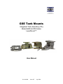
1
GSE Tank Mounts
Integrated Tank Assembly (ITA)
Model 6600 & 6700 Series
LeverMount™
User Manual
39-10-42089
Issue AF
July 2009
© Avery Weigh-Tronix group of companies 2009. All rights reserved.
No part of this publication may be reproduced, stored in an electronic retrieval system, or
transmitted in any form or by any means, electronic, mechanical, photocopying, recording or
otherwise without the prior written consent of the copyright owner, or as permitted by law or under
license. Full acknowledgment of the source must be given. Avery Weigh-Tronix is a registered
trade mark of the Avery Weigh-Tronix group of companies. This publication was correct at the
time of going to print however; Avery Weigh-Tronix reserves the right to alter without notice the
specification, design, price or conditions of supply of any product or service at any time.
All third party brands and product names used within this document are trademarks or registered
trademarks of their respective holders.
Table of Contents
Tank Mount Installation.................................................................................................... 1
Environmental Considerations ................................................................................................. 1
Number and Capacity of Load Cells ........................................................................................ 1
Examples: ............................................................................................................................................... 1
Prepare the Mounting Location ............................................................................................... 2
Mechanical.................................................................................................................................. 2
Installation .................................................................................................................................. 3
Concrete Footing or Floor ...................................................................................................................... 3
Metal Structure ....................................................................................................................................... 3
ITA Only ................................................................................................................................................ 3
Calibration.......................................................................................................................... 4
Maximize Operational Accuracy ....................................................................................... 4
Additional Consideration ................................................................................................... 4
ITA Dimensional Drawings ............................................................................................... 6
Load Cell Specifications ............................................................................................................ 9
Mounting Specifications ............................................................................................................ 9
Load Cell Wiring ....................................................................................................................... 9
6600/6700 Dimensional Drawings .................................................................................. 10
Model 6600 Single Ended Assembly ....................................................................................... 10
Model 6700 Double Ended Assembly ..................................................................................... 11
Load Cell Part Numbers ......................................................................................................... 12
Model 6600........................................................................................................................................... 12
Model 6700........................................................................................................................................... 12
Load Cell Specifications .......................................................................................................... 12
Load Cell Wiring ..................................................................................................................... 12
Model 7300 LeverMount® Quick Reference .................................................................. 13
Unpacking and Setup............................................................................................................... 13
Load Cell Part Numbers ......................................................................................................... 15
Load Cell Specifications .......................................................................................................... 15
Load Cell Wiring ..................................................................................................................... 15
TANK MOUNT INSTALLATION
Environmental Considerations
•
Install the vessel in an environment where temperature fluctuations are minimized and where it will be
protected from wind and drafts.
•
Use load cells with temperature compensation that will allow the most satisfactory performance.
•
Use a shield to protect the load cells from radiant heat sources.
•
If thermal expansion/contraction of the vessel is expected, choose a mount that will allow lateral
movement.
•
Avoid an environment where its support structure is subject to vibration. Minimize vibrations and forces
transmitted via attached piping or vessel restraints.
•
Select load cells and mounts with proper corrosion and moisture protection. Fully welded and sealed,
stainless steel cells provide excellent protection.
•
Use a junction box with appropriate environmental protection.
Number and Capacity of Load Cells
The number of vessel supports determines the number and capacity of the load cells required. It becomes
more difficult to get even weight distribution on all supports as the number of load cells increases beyond
three.
Examples:
UPRIGHT CYLINDRICAL VESSELS IN COMPRESSION
Three or more symmetrically mounted load cells. Three provides the most even weight distribution between
cells. Other factors may require that more supports be used with the vessel for strength or stability. The
fewer number of load cells, the easier to distribute the weight evenly.
RECTANGULAR OR HORIZONTALLY MOUNTED CYLINDRICAL VESSELS IN COMPRESSION
Most practical is four cells, one at each corner of the vessel. Other factors may require that more supports be
used with the vessel for strength or stability. The fewer the number of cells, the easier to distribute the weight
evenly.
SUSPENDED VESSELS (TENSION or COMPRESSION)
One or more load cells may be used. Using three, symmetrically mounted, load cells or fewer has the
advantage of not requiring accurate adjustment of the length of the supports to distribute the weight evenly.
Other factors may require that more supports be used with the vessel for strength or stability.
•
Appropriate individual cell capacity: Calculate Total empty vessel weight + the maximum that the vessel
can hold when filled to overflowing divided by the number of supports. Chose a cell that meets or just
exceeds this calculation. If the vessel is mounted out of doors, additional capacity may be required to
protect from wind induced overload.
•
Do not needlessly oversize the load cells; Best accuracy is achieved when maximum weighing is close to
the load cells capacity.
•
If it is not possible to trim the corners before or after installation then the use of load cells with matched
outputs is desirable. If the vessel is not symmetrical and/or the material is not self-leveling, trimming or
matching is a necessity for accuracy.
•
Support the vessel entirely on load cells; do not use dummy cells or flexures that would hinder good
performance.
1
Prepare the Mounting Location
To insure precise operation, the mounting surface for the tank mount top and bottom plates must be level. If
the mounting surfaces are not level, use shims and/or grout to level the surface. The top and bottom plates
must be level within ±0.5°.
NOTE: Be sure to use dummy load cells during installation to avoid overloading the actual load cell.
Determine where to position the tank mount assembly and in which direction it should be oriented. The tank
mount assembly is designed to allow for lateral movement in the direction perpendicular to the load cell.
Mechanical
•
Support the load cell mounts on a rigid structure so that all points are equally supported and the vessel
stays vertical. Vehicular traffic or other forces must not cause deflection of the vessel’s support
structure.
•
Ladders, pipes and check rods, etc. must have as little interaction with the vessel as possible.
•
Where piping or conduit must be attached to the vessel: Use the smallest diameter, thinnest walled pipe
that will meet all other specifications. Use the longest reasonable unsupported horizontal length to
connect the vessel. 25 times the pipe diameter as a minimum to the first support or use a horizontally
mounted flexible connection.
•
There must be no tension between electrical cables or hoses and the vessel.
•
Mount pneumatic solenoids for integral gates or valves on the vessel then connect the supply lines
horizontally as in piping.
•
Attached piping is usually the largest source of error in vessel weighing. The lower the capacity of the
vessel the more likely inaccuracies of this type will be apparent. Correctly installed piping and electrical
connections followed by an in place calibration will result in the best system performance.
2
Installation
Concrete Footing or Floor
1. Position tank mount assembly bottom plate on foundation and use as a template for hole patterns.
2. Remove bottom plate drill holes.
3. Install threaded rods in the foundation. Make sure the rods line up with the holes in the tank mount
assembly plates.
4. Install leveling nuts on threaded foundation rods.
5. Place tank mount assembly over threaded rods and align tank mount assembly in plane of maximum
thermal expansion/contraction.
6. Loosely attach nuts to foundation rods and tank mount assembly. Do not tighten nuts at this time.
7. Level and plumb the tank mount assembly (0.5°).
Metal Structure
1. Position tank mount assembly on beam or support and use as a template for hole patterns. Be sure
to center the tank mount with shear center of support beam.
2. Remove tank mount assembly and drill holes.
3. Align tank mount in plane of maximum thermal expansion/contraction.
4. Install bolts and nuts loosely. Do not tighten at this time.
5. Level and plumb the tank mount assembly (0.5°).
ITA Only
Install the ITA as you would most tank mount load cells. The following is a guide to insure maximum
performance from your system.
Prepare the ITA: The ITA top Plate must move freely. Every ITA comes from the factory correctly
assembled and locktighted and should not require adjustment.
The load must be applied vertically to the load cells.
a. Use a level to insure that the base plate is level. If not, level the supporting points, if this is not
possible then shim the load cell base plate.
b. Use a level to insure that the load cell is level then lower the vessel close to the load cell.
c. Visually inspect the foot of the vessel support to insure that it aligns evenly with the level load cell. If
it does not, shim the foot so that the load cell remains level.
If a temperature insulator is required between the foot and the load cell, use only a rigid isolator. Only the
outer load cell ring may contact the foot or insulator.
If the ITA has been disassembled for any reason, perform the following:
a. Remove the large center screw.
b. Align the convex load disc and the load cell with the center hole in the base plate.
c. Locktight and install the large screw and continue to turn it until the Rubber O-Ring just contacts the
convex load disc.
d. Back the screw off ¼ turn. The Screw provides lateral restraint and lift off protection, never remove it
or back it off more than the suggested amount.
The center portion of the ITA load cell mount is not live. Therefore, if any part of the tank leg or
adapter plate makes contact with the center, it will affect the weighing accuracy of the system.
3
CALIBRATION
•
Ideally the vessel will have a means of hanging weight from the corners of the vessel to trim the load cell
outputs and for calibration. If it is not possible use test weights to calibrate, a known amount of product
or substitute should be used.
•
Calibration in place can help compensate for interference from piping, electrical connections and slightly
misaligned load cells.
MAXIMIZE OPERATIONAL ACCURACY
•
If using a GSE indicator, try the Future Gross parameter. This feature calculates the cutoff point based
on current flow rate and a manually entered freefall time.
•
An evenly flowing material can be most accurately measured. Reduce to a minimum the surging (i.e.
diaphragm pump) of liquids while a weight reading is being taken.
•
Slow down the filling cycle as much as possible or use a 2-speed fill cycle to reduce to a minimum the
amount of freefall material when nearing the cutoff.
•
If possible, switch off any vibrating or mixing equipment while the weight is being determined.
ADDITIONAL CONSIDERATION
The GSE tank mounts are self checking with integral lift off restraint, however, additional vessel restraints
may be required to prevent a vessel from falling from unexpected forces, protect connections from fatigue or
to keep connections aligned.
Check Rods and Stay Rods can be identical with the exception of the actual connection to the vessel. The
following Table lists their traits and uses.
Check Rods
Stay Rods
Prevent excessive Motion
Prevent any Horizontal Motion
Can be mounted Vertically for suspended vessels. Used to
prevent falling in case of a catastrophic load cell failure.
Cannot be used vertically
Mounting is Tangential for Circular Vessels – Parallel for Rectangular Vessels
Installed without Tension or Compression
Installed with slight Tension
Should have no effect on accuracy
Should have minimal effect on accuracy. Length and diameter of
the rod directly influences this. Use the longest, thinnest rod of
suitable strength.
4
Never Exceed Recommended Bolt torque. An over torqued bolt can be structurally weakened.
LC …Low Carbon
MC…Medium
Carbon
Q…Quenched
T…Tempered Steel
A…Alloy
SAE 0-2 LC
74000 PSI
Lubrication
Factors
SAE 5 MC T
120000 PSI
SAE 6 MC QT
133000 PSI
SAE 7 MC QTA
133000 PSI
SAE 8 MC QTA
150000 PSI
Approximate Dry Torque Coarse / Fine
Bolt-Coarse *Fine
¼-20 *28
5/16-18 *24
3/8-16 *24
7/16-14 *20
½-13 *20
9/16-12 *18
5/8-11 *18
¾-10 *16
7/8-9 *14
1-8 *14
1 1/8-7 *12
1 ¼-7 *12
1 3/8-6 *12
1 ½-6 *12
SAE 3 MC
100000 PSI
4/6
9/12
16/22
24/34
38/52
52/71
98/115
155/180
206/230
310/350
480/523
675/736
900/981
1100/1200
9/10
17/19
30/33
47/51
69/75
103/112
145/158
234/255
372/405
551/600
794/865
1105/1204
1500/1635
1775/1935
10/11
19/21
33/36
54/59
78/85
114/124
154/168
257/280
382/416
587/640
872/950
1211/1320
1624/1770
1943/2118
10/12
21/23
39/44
60/69
94/99
133/147
135/205
310/350
500/560
780/840
1305/1425
1790/1950
2425/2655
2915/3175
10/12
21/24
40/45
60/70
95/100
135/150
140/210
320/360
520/580
800/860
1325/1444
1825/1989
2500/2725
3000/3270
12/14
25/29
45/50
70/80
110/120
150/170
220/240
380/420
600/660
900/990
1430/1559
1975/2153
2650/2888
3200/3488
Zinc Plate
Cadmium Pl
Chrome Pl
Dry Film
Oil
Oil/Graphite
-15%
-25%
N/C
-50%
-15-40%
-55%
5
ITA DIMENSIONAL DRAWINGS
Figure 1: ITA Dimensions 1 K to 125 K
6
Figure 2: ITA Dimensions 150 K to 450 K
7
Figure 3: Mounting Plate Dimensions 1K - 10K
Figure 4: Mounting Plate Dimensions 20K - 125K
8
Figure 5: Mounting Plate Dimensions 150K - 225K
Load Cell Specifications
Construction
Exc. Voltage
Output
Temp Range
Bridge Resistance
Insulation Resistance
Linearity
Repeatability
Max load safe
Max Load ultimate
1K to 10 K
Stainless Steel, Hermetic
10 – 15 VDC or VAC
3 mV/V nominal
10° F to 100° F
350 Ohms nominal
5000 Meg Ohms min
0.05 % Full Scale
0.01 % Full Scale
150 % of rated capacity
300 % of rated capacity
20 K to 50 K
Stainless Steel, Hermetic
10 – 15 VDC or VAC
3 mV/V nominal
10° F to 100° F
350 Ohms nominal
5000 Meg Ohms min
0.05 % Full Scale
0.01 % Full Scale
150 % of rated capacity
300 % of rated capacity
60 K to 125 K
Stainless Steel, Hermetic
10 – 15 VDC or VAC
3 mV/V nominal
10° F to 100° F
350 Ohms nominal
5000 Meg Ohms min
0.05 % Full Scale
0.01 % Full Scale
150 % of rated capacity
300 % of rated capacity
150 K to 225 K
Stainless Steel, Hermetic
10 – 15 VDC or VAC
3 mV/V nominal
10° F to 100° F
350 Ohms nominal
5000 Meg Ohms min
0.05 % Full Scale
0.01 % Full Scale
150 % of rated capacity
300 % of rated capacity
Mounting Specifications
Uplift Restraint
Lateral Restraint
Non- Parallel Accommodation
Thermal Accommodation
1K to 10 K
100 % of rated capacity
100 % of rated capacity
±3“
± .1 °
20 K to 50 K
100 % of rated capacity
100 % of rated capacity
±3“
± .17 °
Load Cell Wiring
+ Excitation
- Excitation
+ Signal
- Signal
Green
Black
White
Red
9
60 K to 125 K
100 % of rated capacity
100 % of rated capacity
±3“
± .2 °
150 K to 225 K
100 % of rated capacity
100 % of rated capacity
±3“
± .25 °
6600/6700 DIMENSIONAL DRAWINGS
Model 6600 Single Ended Assembly
Balloon Quantity
1
2
3
4
5
6
7
8
9
10
1
1
2
2
1
1
4
4
1
1
Carbon Steel
Part Number
Stainless
Steel
Part Number
44-45-43431
44-45-43434
34-01-XXXXX
34-08-XXXXXA
38-56-1410
38-56-8970
44-10-43433
44-10-43436
44-45-43432
44-45-43435
38-44-1355
38-44-5815
38-56-1500
38-56-1510
38-60-8835
Description
Tank assembly base
Loadcell sensor
1/2” split lock washer, Stainless Steel
1/2” – 13X2.25, hex HD, Stainless Steel
Tank attach plate,
Tank support
5/16” washer, split lock, Stainless Steel
5/16” – 18x0.75, hex HD, Stainless Steel
1/2” self aligning washer
1/2” – 20x2.25, hex HD, Stainless Steel
10
Model 6700 Double Ended Assembly
Balloon Capacit
y
1
1 – 5K
10 – 25K
50K
75K
2
3
4
5
6
7
8
Quanti
ty
1
CS Part Number
44-45-43441
44-45-43451
44-45-43468
44-45-43475
1
1 – 5K
10 – 25K
50K
75K
1 – 5K
10 – 25K
50K
75K
1 – 5K
10 – 25K
50K
75K
1 – 5K
10 – 25K
50K
75K
1 – 5K
10 – 25K
50K
75K
1
1
2
2
2
2
44-45-43442
44-45-43452
44-45-43469
44-45-43476
44-10-43443
44-10-43453
44-10-43470
44-10-43477
38-81-1300
38-81-1300
38-81-1200
38-81-1200
44-10-43444
SS Part Number
44-45-43445
44-45-43455
44-45-43472
44-45-43478
34-01-XXXXX
44-45-43446
44-45-43456
44-45-43473
44-45-43479
44-10-43447
44-10-43457
44-10-43474
44-10-43480
38-56-1410
38-77-1360
38-81-1301
38-81-1301
38-56-8980
38-77-5830
38-81-1201
38-81-1201
44-10-43491
44-10-43454
44-10-43471
44-10-43471
38-85-165HP
11
Description
Tank assembly base
Loadcell sensor
Tank support
Tank attach plate
1/2” split lock washer, Stainless Steel
3/4” split lock washer, Stainless Steel
1.25” split lock washer, Stainless Steel
1.25” split lock washer, Stainless Steel
1/2” – 13X2.5, hex HD, Stainless Steel
3/4” - 10X3.50, hex HD, Stainless Steel
1.25”, 7X5.00, hex HD, Stainless Steel
1.25”, 7X5.00, hex HD, Stainless Steel
7/16” tank assembly rod
3/4” tank assembly rod
1.25” tank assembly rod
1.25” tank assembly rod
3/32”, DIA, Cotter pin, Stainless Steel
Load Cell Part Numbers
Model 6600
Carbon Steel
Part Number
Stainless Steel
Part Number
34-01-03102
34-01-03202
34-01-03252
34-01-03402
34-01-04502
34-08-02102A
34-08-02202A
34-08-02252A
34-08-02402A
34-08-02502A
Capacity
Carbon Steel
Part Number
Stainless Steel
Part Number
2K
2.5K
3K
5K
10K
15K
20K
25K
50K
75K
34-01-10202
34-01-10252
34-01-10302
34-01-10502
34-01-12103
34-01-12153
34-01-12203
34-01-12253
34-01-14503
34-01-14753
34-01-11202
34-01-11252
34-01-11302
34-01-11502
34-01-13103
34-01-13153
34-01-13203
34-01-13253
34-01-15503
34-01-15753
Capacity
1K
2K
2.5K
4K
5K
Model 6700
Load Cell Specifications
Mild Steel Single Ended
Construction
Cable Length
Exc. Voltage
Output
Temp Range
Bridge Resistance
Non - Repeatability
Safe Overload
Ultimate Overload
Alloy tool steel
20 feet (6.1 m)
15 VDC
3 mV/V
0 °F to 150 °F (-18 °C to 65
°C)
350 ohm
± 0.01 % of rated output
150 % of Rated capacity
300 % of Rated capacity
Stainless Steel Single
Ended
Stainless steel
15 VAC/VDC
3 mV/V
-4 °F to 140 °F (-20 °C to
60 °C)
350 ohm
± 0.02 % of rated output
150 % of Rated capacity
300 % of Rated capacity
Load Cell Wiring
+ Excitation
- Excitation
+ Signal
- Signal
Red
Black
Green
White
12
Mild Steel Double Ended
Alloy tool steel
25 feet (7.62 m)
15 VAC/VDC
3 mV/V
0 °F to 150 °F (-18 °C to 65
°C)
700 ohm
± 0.01 % full scale output
150 % of Rated capacity
300 % of Rated capacity
Stainless Steel Double
Ended
Stainless steel
25 feet (7.62 m)
15 VAC/VDC
3 mV/V
0 °F to 150 °F (-18 °C to 65
°C)
700 ohm
± 0.01 % full scale output
150 % of Rated capacity
300 % of Rated capacity
MODEL 7300 LEVERMOUNT® QUICK
REFERENCE
Unpacking and Setup
1. Unpack the LeverMount® assembly and the load cell. Do not
loosen the transit bolts yet. Check the items are not damaged
and that all the intended parts are included. Each LeverMount®
shipping assembly should contain
• 1x LeverMount® Assembly
• 1x Load Cell
• 1x Load Button
2. Rotate the saddle in the top bracket so that when the LeverMount®
assembly is in its final position, the slot in the saddle will be aligned
in the direction of the maximum expansion of movement, which is
generally pointing into the center of the weigh vessel.
3. Mount the Levermount® assembly in position on the load bearing structure, and securely bolt it via the
three slots in the bottom bracket. The attachment bolts are not supplied with the assembly and the
required quantities are listed in the table below:
LeverMount® Product Type
20 – 500 lb
10 – 200 kg
1K – 5K lb
500 – 2K kg
5K – 10K lb
2K – 5K kg
LeverMount®
Lite
LeverMount®
LeverMount®
Bolt
Size
5/16”
M8
7/16”
M12
3/4”
M20
Bottom
Bracket Nuts
and Bolts
Top Bracket
Nuts and
Bolts
3
4
3
4
3
4
4. Position the vessel or structure to be weighed on the top bracket of the
LeverMount®. Bolt the mating foot of the vessel or structure to the top
bracket of the LeverMount® using two additional bolts (not supplied) in
the free slots.
WARNING: The raised strip on the top bracket must be aligned with the two
arrows on the mount to prevent serious injury or death.
NOTE: Be sure to consider all circumstances such as expected wind load
and tank height. Additional measures may need to be taken to insure
stability and prevent toppling of the weigh vessel.
13
5. Loosen the two transit bolts and slide them free with the nuts. DO
NOT DISCARD THE BOLTS AND WASHERS. The top bracket
should be further secured to the vessel or structure using two
additional bolts and washers (not supplied). Check that the top
bracket raised strip is still aligned with the two arrows on the
mount. At this stage the vessel is completely supported by the
LeverMount® assembly.
6. Ensure that the direction arrow on the front face of the load cell is
pointing down and that all mating surfaces are free of debris. Fit the
load button to the load cell and then slide the load cell, with the load
button in place, into position within the LeverMount® assembly.
Insert the two transit bolts and washers through the load cell fixing
holes and hand tighten. Ensure the load cell is parallel to the center
line of the LeverMount® assembly and alternately tighten the bolts.
7. Alternate the tightening of the two bolts to the specified torque in the table below. This will
raise the weight vessel and transfers the load to the load cell leaving it ready for operational
weighing.
LeverMount® Product Type
Bolt Torque
20 – 500 lb
LeverMount® Lite
24 lb-ft
10 – 200 kg
LeverMount® Lite
32Nm
1k – 5k lb
LeverMount®
118 lb-ft
500 – 2k kg
LeverMount®
160Nm
5K – 10K lb
LeverMount®
118 lb-ft to Lift 50%
of capacity
2K – 5K kg
LeverMount®
160Nm to Lift 50% of
capacity
NOTE: Periodically check the security of the mount and the attachment vessel.
14
Load Cell Part Numbers
Capacity
Product
Part Number
20
50
100
200
250
500
500
1000
2000
4000
5000
10000
LeverMount® Lite
LeverMount® Lite
LeverMount® Lite
LeverMount® Lite
LeverMount® Lite
LeverMount® Lite
LeverMount® Medium
LeverMount® Medium
LeverMount® Medium
LeverMount® Medium
LeverMount ® Large
LeverMount ® Large
34-02-10200
34-02-10500
34-02-10101
34-02-10201
34-02-10251
34-02-10501
34-08-02501A
34-08-02102A
34-08-02202A
34-08-02402A
34-08-02502LA
34-08-02103A
Load Cell Specifications
LeverMount® Lite
Construction
Cable Length
Exc. Voltage
Output
Temp Range
Bridge Resistance
Non-Linearity
Non-Repeatability
Safe Overload
Ultimate Overload
LeverMount®
316 cast stainless steel
9.8 feet (3 m)
16.5 feet (5 m)
10 - 15 VAC/VDC
10 - 15 VAC/VDC
2 mV/V
3 mV/V
-22 °F to 176 °F (-30 °C to 80 °C) -4 °F to 140 °F (-20 °C to 60 °C)
350 ohm
350 ohm
± 0.025% of rated output
± 0.02% of rated output
150 % of Rated capacity
150 % of Full Scale
300 % of Rated capacity
300 % of Full Scale
Load Cell Wiring
+ Excitation
- Excitation
+ Signal
- Signal
Green
Black
White
Red
15
Avery Weigh-Tronix USA
1000 Armstrong Dr.
Fairmont MN 56031 USA
Tel:507-238-4461
Fax:507-238-4195
Email: [email protected]
www.wtxweb.com
Avery Weigh-Tronix UK
Foundry Lane,
Smethwick, West Midlands,
England B66 2LP
Tel:+44 (0) 8453 66 77 88
Fax: +44 (0)121 224 8183
Email: [email protected]
www.averyweigh-tronix.com