1
4.1 Connecting to the Modbus network
4.3 Setting the parity
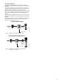
A screened, twisted-pair cable must be used. The cable screen
must be connected to protective earth at both ends.
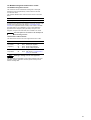
The parity can be set either manually by using SW3 or via
software-defined settings.
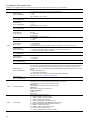
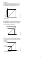
Recommended connection
Manual setting of parity
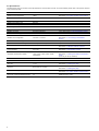
Colour code
Data signal
The CIM 200 only supports the Modbus RTU mode and hence
cannot communicate with Modbus ASCII mode devices.
D1-TXD1
Yellow
Positive
Default byte format (11 bits):
D0-TXD0
Brown
Negative
•
1 start bit
Common/GND
•
8 data bits (least significant bit sent first)
•
1 parity bit (even parity)
4.2 Setting the Modbus transmission speed
•
1 stop bit.
The transmission speed must be set correctly before the CIM 200
Modbus module is ready to communicate with the Modbus
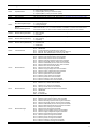
network. DIP switches SW4 and SW5 are used for setting the
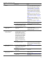
transmission speed. See fig. 5.
The default setting of the CIM 200 Modbus module is even parity
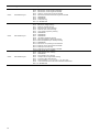
(1 stop bit). It is possible to change the parity with DIP switch
SW3. The parity can be changed to no parity (2 stop bits).
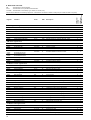
See fig. 6.
Grey
TM04 1710 0908
Common
SW4 SW5
Fig. 5
Modbus transmission speed setting
SW3
Fig. 6
4.2.1 DIP switch settings
TM04 1709 0908
Modbus terminal
Parity
DIP switch settings
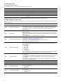
Available transmission speeds in bits/s: 1200, 2400, 4800, 9600,
19200 and 38400.
The first three transmission speeds are only available via
software settings, whereas the last three are available via
DIP switches SW4 and SW5.
Parity
SW3
Even parity, 1 stop bit
OFF
No parity, 2 stop bits
ON
Software-defined parity and stop bit
Transmission speed
SW4
SW5
9600 bits/s
OFF
ON
19200 bits/s
OFF
OFF
38400 bits/s
ON
OFF
Software-defined
ON
ON
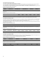
When SW4 and SW5 are set to "software-defined", the value in
holding registers at addresses 00009 and 00010 will override the
setting of SW3. See figs 5 and 6.
Software-defined parity
Set register value
00009
The default transmission speed is 19200 bits per second, as per
the Modbus RTU standard.
No parity [default]
Even parity
1
The transmission speed will be effective immediately after setting
the values of the DIP switch.
Odd parity
2
Software-defined
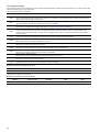
When SW4 and SW5 are set to "software-defined", writing a
value to the holding register at address 00004 will set a new
transmission speed.
Use the following values for software-defined transmission
speeds:
Software-defined transmission
speed
0
2400 bits/s
1
4800 bits/s
2
9600 bits/s
3
19200 bits/s
4
38400 bits/s
5
This value is set to 1200 bits/s as default.
The communication interface does not support transmission
speeds above 38400 bits/s.
The software-defined transmission speed value will be stored
in the communication interface and will remain after a power-off.
6
When software-defined transmission speed is
enabled (ON), software-defined parity and stop
bit are also enabled.
Set register value
00010
1 stop bit [default]
1
2 stop bits
2
The software-defined parity and stop bit values will be stored in
the communication interface and will remain after a power-off.
Set register value
00004
1200 bits/s
Note
Software-defined stop bit
0
Note
Before the parity and stop bit can be set via
software-defined settings, SW4 and SW5 must be
set to ON.