1
HCFA CORPORATION LIMITED
User’s Manual
for HCA4 series Programmable controller
1. Product overview
1.1 Product naming rules
Code
Contents
①
HC indicates the Chinese Characters Pinyin Initials ‘Hechuan’
②
A4 indicates series number of PLC.
③
36X indicates 36 input points;
HC PLC Types: A1~A8
Input points of A4 series: 8X, 14X, 20X, 24X, 28X, 36X
④
24Y indicates 24 output points;
Output points of A4 series: 8Y,12Y, 14Y, 16Y, 20Y, 24Y
Total number of input& output points:
16 points, 26 points, 34 points, 40 points, 48 points, 60 points
⑤
R(T) indicates output type of PLC
R: relay output
⑥
T: transistor output
A(D) indicates power supply type of PLC
A: 85V~264V AC input
D: 20.4V~26.4V DC input
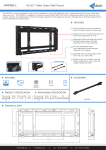
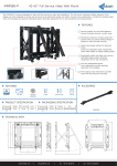
1.2 Part names
Example: HCA4-36X24YR-A
①Status indicator
POWER LED: Lit when power is ON.
RUN LED: Lit when executing a program in either RUN or MONITOR mode
Not lit when Operation is stopped in PROGRAM mode or due to a fatal error
ERROR LED: Flash when a non-fatal error has occurred (including battery alarm). HCA4
1
operation will continue.
Lit when a fatal error or a hardware error has occurred. HCA4 operation will
stop and all outputs will be turned OFF.
②Input indicator: HCA4 input is duodecimal. One channel for 12 points.
③Output indicator: HCA4 output is octal. One channel for 8 output points
④RS422 &485 Communication port: Operating according to arrow directions
⑤RS422 Communication port: Operating according to arrow directions
⑥USB port: Used to connect to a personal computer for programming and monitoring by
the Programmer for HCA4
(Installation procedure: Start Windows and insert the Programmer for HCA4 Master Disk
in the CD-ROM drive.
The installation program will be started by the computer’s auto-run function. Complete the
installation process following the instructions provided on-screen.)
⑦Terminal cover
⑧The right extension cover
⑨ The front cover, built-in battery interface
10 Two analog potentiometer opening
○
1.3 External dimension
Points
L(mm)
W(mm)
H(mm)
HCA4-8X8Y(16 points)
100.2
90
81
HCA4—14X12Y (28 points)
130.2
90
81
HCA4—20X14Y (34 points)
150.2
90
83
HCA4—24X16Y (40 points)
182.2
90
83
HCA4—28X20Y (48 points)
182.2
90
83
HCA4—36X24Y (60 points)
220.2
90
83
1.4 Performance specification
Items
Performance
Program capacity
8K steps
DM Area capacity
8K words, of these 7K words can be written to the built-in EEPROM.
Mounting expansion
Available (Not yet introduced)
units and expansion
I/O units
Models with transistor
Available
outputs
High-speed counter
●Increment: 100 kHz ×2 counters, 10 kHz × 4 counters
●Up/ down: 100 kHz × 1 counter, 10 kHz ×1 counter
●Pulse plus direction: 100 kHz ×2 counters
●Differential phases (4×): 50 kHz × 1 counter, 5kHz ×1 counter
Pulse output
Supported (Models with transistor outputs only)
Built-in RS422
Provided(Online function of the port can be used only by the programming
communication port
software ver. 9.2 or higher)
Built-in RS422& 485
Provided(Online function of the port can be used only by the programming
2
communication port
software ver. 9.2 or higher)
Connection port for
USB port
programming device
Clock
Provided
Using a battery
Can be used(Sold separately)
Back-up time of
Max. 10 days at 25°C (Normal starting for more than 15 minutes)
built-in capacitor
Battery-free
Battery-free operation if no battery is attached.
operation
In this case, only data in the built-in EEPROM will be retained if the power is
interrupted for longer than 8 or 10 days.
★Precaution
for correct use
For HCA4 CPU units, the following I/O area will be unstable after a power interruption.
•DM area (D) (Excluding the words backed up to the EEPROM using the DM function)
•Holding area (H)
•Counter present values and completion flags(C)
•Auxiliary area related to clock function (A)
Mount the battery (sold separately) to a CPU unit if the data in above area need to be
retained after a power interruption.
2 Power specification
2.1 AC Power module specification
Items
16
26
points
points
34 points
Supply voltage
100 - 240V AC, +10% -15%
Operating voltage
85 to 264 VAC
40 points
48 points
range
Rated frequency
50/60 Hz
Allowable
10ms, If less than 10 ms, the PLC will continue operation.
momentary
power
If 10 ms or more, the PLC will be shut down
failure period
Power fuse
250 V, 1 A
Inrush current
100 V AC –Max.15 A for 5ms
200 V AC –Max.25 A for 5ms
Power
21 W
30 W
consumption(W)
24V DC External
24V DC 400mA
power supply
3
60 points
2.2 DC Power module specification
Items
16
26
points
points
Supply voltage
24V DC, +10% -15%
Operating voltage
20.4 to 26.4 V
34 points
40 points
48 points
range
Allowable
momentary
5ms, If less than 5 ms, the PLC will continue operation.
power
If 5 ms or more, the PLC will be shut down
failure period
Inrush current
15 A for 0.1ms
Power
8W
15 W
consumption(W)
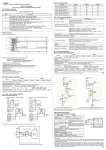
3 Input/ output wiring diagram
3.1 Input wiring diagram
Programmable controller (Sinking)
Programmable controller (Sourcing)
Wiring diagram of input terminal (Sinking/ sourcing)
a) 2*100 KHZ Internal circuit of high-speed input
4
60 points
b) CIO0.02-0.07 internal circuit
c) CIO0.08-2.11 internal circuit of normal input
★Precaution for correct use:
Unidirectional coupling was used in photocoupler input for all HCA4 series, and all inputs
can only be sinking input.
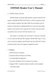
3.2 Output wiring diagram
3.2.1 Relay output specification and wiring
Output type
Relay
≤30V DC
External power supply
≤240V AC ("250V AC or less" if not a CE, UL,
cUL compliant item)
Maximum load
Resistive load
2A / 1 point
The total load current should not
exceed following values of
common collector.
Output 1 point common collector:
2A
Output 4 point common collector:
8A
Output 8point common collector:
8A
5
Inductive load
80 VA
Minimum load
5 VDC 2mA (Reference value)
Open circuit leakage current
--
Response time
OFF→ON
About 10 ms
ON→OFF
About 10 ms
Circuit isolation
Mechanical isolation
Operation indication
When relay coil is energized, LED is lit.
★Precaution for correct use:
The load short-circuit protection circuit: When the output terminal load short-circuited,
printed circuit board may be burned. Please insert the fuse in the output.
Contact protection circuit of inductive load: An internal protection circuit for the relays is
not provided in the relay output circuit for this product. It is recommended to use inductive
loads with built-in protection circuits. When using loads without built-in protection circuits,
insert an external contact protection circuit composed of surge absorber to reduce
electromagnetic interference and extend the product life.
3.2.2 Transistor output specification and wiring
1. Sinking output wiring
2. Sourcing output wiring
External power supply
Maximum load
5~30 V DC
Resistive load
The total load current should not exceed the
following values of common collector resistance
load.
Output 1 point common collector: 0.5A
Output 4 point common collector: 0.8A
Output 8point common collector: 1.6A
Inductive load
12 W/ 24V DC
Minimum load
--
Open-circuit leakage current
≤0.1 mA / DC30V
ON voltage
≤1.5V
6
★Precaution for correct use
All outputs are set as sinking output modes in all HCA4 series with transistor output.
4 Guidelines for high-speed counter input and pulse output
●4.1 Example of using high-speed counter input
The overall procedure for using built-in HCA4 functions is described below.
1
Select the function to use.
Select functions
Example: Interrupts, high-speed counter input and pulse output.
2
Set the function with applicable numbers using the CX-programmer.
Making the settings in
Example: Input interrupt IN3 and high-speed counter 0. Parameters in the PLC Setup must
the PLC setup
be set for the following function:
3
•Input interrupt
•Origin searches
•Quick-response input
•Minimum cycle time
•High-speed counters
•Serial communications
Write ladder diagrams using the CX-programmer.
Create ladder program
Example: Permitting interrupts with the MSKS instruction and programming high-speed
Special instructions
Writing related auxiliary
counters with the CTBL instruction.
Example: Stopping high-speed counters.
area words
Example: Reading the present value of a high-speed counter.
Reading related
auxiliary area words
4
Transfer
PLC
setup
Transfer the PLC setup and ladder program from the CX-programmer to the CPU unit.
and ladder program
5.
Restart PLC power
Set the power of HCA4 CPU unit OFF, then ON again,.
6
Start operation
Start PLC operation.
7
★Precaution for correct use:
The power supply must be restarted after the PLC Setup is modified and transferred in
order to enable the settings.
Click the ‘Built-in Input’ Tab and select the ‘Use high-speed counter’ Check Box for
high-speed counters 0 to 5, and then set the counting mode, reset method, and input
setting.
●Reading the High-speed Counter present value(PV) with a PRV Instruction
●Reading the High-speed Counter Frequency with a PRV Instruction
Items
Number of frequency measurement
Specification
1 input (high-speed counter 0 only)
inputs
Frequency measurement range
High-speed counter 0:
Differential phase inputs: 0 to 50 kHz
All other input modes: 0 to 100 kHz
Note: If the frequency exceeds the maximum value, the
maximum value will be stored.
Measurement method
Execution of the PRV instruction
Stored data
Unit
Hz
Output data range
Differential phase input: 0000 0000 to 0003 0D40 hex
All other input modes: 0000 0000 to 0001 86A0 hex
★Restrictions
• The frequency measurement function can be used with high-speed counter 0 only.
●4.2 Example of using pulse output(Only for transistor output models)
SPED Instruction pulse output is used to specify the frequency and perform pulse output
without acceleration or deceleration.
8
P: Port specifier
0000 hex
Pulse output 0
0001 hex
Pulse output 1
M: Output mode
F: First pulse frequency word
The unit of pulse frequency value is Hz.
5 Terminal arrangements for HCA4 series
9
Difference between DC power terminal and AC power terminal:
AC power supply
DC power supply
Manual NO. : HCFA-HC-HCA4-001
Date: Nov.15th, 2013.
10