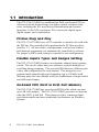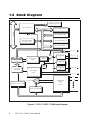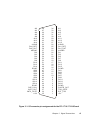
1
PCI-1710/1710HG Multifunction DAS Card for PCI Bus User's manual Copyright This documentation and the software included with this product are copyrighted 1998 by Advantech Co., Ltd. All rights are reserved. Advantech Co., Ltd. reserves the right to make improvements in the products described in this manual at any time without notice. No part of this manual may be reproduced, copied, translated or transmitted in any form or by any means without the prior written permission of Advantech Co., Ltd. Information provided in this manual is intended to be accurate and reliable. However, Advantech Co., Ltd. assumes no responsibility for its use, nor for any infringements of the rights of third parties which may result from its use. Acknowledgments PC-LabCard is a trademark of Advantech Co., Ltd. IBM and PC are trademarks of International Business Machines Corporation. MS-DOS and Windows are trademarks of Microsoft Corporation. Intel and Pentium are trademarks of Intel Corporation. CE notification The PCI-1710/1710HG, developed by ADVANTECH CO., LTD., has passed the CE test for environmental specifications when shielded cables are used for external wiring. We recommend the use of shielded cables. This kind of cable is available from Advantech. Please contact your local supplier for ordering information. On-line Technical Support For technical support and service please visit our support website at http:/support.advantech.com Part No. 2003171010 2nd Edition Printed in Taiwan Feburary 1999 Contents Chapter 1: General Information ............................. 1 1.1 1.2 1.3 1.4 Introduction ............................................................... 2 Features .................................................................... 3 Specifications............................................................. 4 Block Diagram........................................................... 8 Chapter 2: Installation .............................................. 9 2.1 2.2 2.3 Initial Inspection ....................................................... 10 Unpacking ............................................................... 10 Installation Instructions ............................................. 11 Chapter 3: Signal Connections .............................. 13 3.1 3.2 3.3 3.4 3.5 3.6 Overview................................................................. 15 I/O Connector ......................................................... 15 Analog Input Connections ........................................ 19 Analog Output Connections ..................................... 23 Trigger Source Connections ..................................... 25 Field Wiring Considerations...................................... 25 Chapter 4: Register Structure and Format ......... 27 4.1 4.2 4.3 4.4 4.5 4.6 Overview................................................................. 28 I/O Port Address Map............................................. 28 Channel Number and A/D Data ............................... 33 Software A/D Trigger............................................... 33 A/D Channel Range Setting ...................................... 34 MUX Control .......................................................... 37 4.7 4.8 4.9 4.10 4.11 4.12 4.13 4.14 Control Register....................................................... 39 Status Register ......................................................... 40 Clear Interrupt and FIFO ......................................... 41 D/A Channel 0 Output ............................................. 42 D/A Channel 1 Output ............................................. 42 D/A Reference Control ............................................ 43 Digital I/O Registers ................................................. 44 Programmable Timer/Counter Registers .................... 44 Chapter 5: Calibration............................................ 45 5.1 5.2 5.3 5.4 5.5 Introduction ............................................................. 46 VR Assignment ........................................................ 46 A/D Calibration ....................................................... 47 D/A Calibration ....................................................... 48 Self A/D Calibration................................................. 49 Appendix A: 82C54 Counter Chip Functions ...... 51 A.1 A.2 A.3 A.4 The Intel 82C54 ...................................................... 52 Counter Read/Write and Control Registers ............... 53 Counter Operating Modes ....................................... 56 Counter Operations ................................................. 58 CHAPTER 1 General Information Chapter 1 General Information 1 1.1 Introduction The PCI-1710/1710HG is a multifunction DAS card for the PCI bus. Advanced circuit design brings you higher quality and more functions, including the five most desired measurement and control functions: 12-bit A/D conversion, D/A conversion, digital input, digital output, and counter/timer. PCI-bus Plug and Play The PCI-1710/1710HG uses a PCI controller to interface the card with the PCI bus. The controller fully implements the PCI bus specification Rev 2.1. All bus relative configurations, such as base address and interrupt assignment, are automatically controlled by software. No jumper or DIP switch setting is required for user configuration. Flexible Inputs Types and Ranges Setting The PCI-1710/1710HG features an automatic channel/gain scanning circuit. The circuit, rather than your software, controls multiplexer switching during sampling. The on-board SRAM stores different gain values and configuration for each channel. This design lets you perform multi-channel high-speed sampling (up to 100 kHz) with different gains for each channel with free combination of single-ended and differential inputs. On-board FIFO (First In First Out) Memory The PCI-1710/1710HG has an on-board FIFO buffer which can store up to 4K A/D samples. The PCI-1710/1710HG generates an interrupt when the FIFO is half full. This feature provides continuous highspeed data transfer and more predictable performance on Windows systems. 2 PCI-1710 /1710HG User's Manual On-board Programmable Counter The PCI-1710/1710HG provides a programmable counter for generating a pacer trigger for the A/D conversion. The counter chip is an 82C54 or equivalent, which includes three 16-bit counters on a 10 MHz clock. One counter is used as an event counter for counting events coming from the input channels. The other two are cascaded together to make a 32-bit timer for a pacer trigger. 1.2 Features • 16 single-ended or 8 differential analog inputs, or a combination • 12-bit A/D converter, with up to 100 kHz sampling rate • Programmable gain for each input channel • Automatic channel/gain scanning • On-board 4K samples FIFO buffer • Two 12-bit analog output channels • 16 digital inputs and 16 digital outputs • Programmable pacer/counter Chapter 1 General Information 3 1.3 Specifications Analog Input: • Channels: 16 single-ended or 8 differential (software programmable) • Resolution: 12-bit • On-board FIFO: 4K samples • Conversion time: 8 µs • Input range: (V, software programmable) PCI-1710 PCI-1710HG Bipolar ±10, ±5, ±2.5, ±1.25, ±0.625 ±10, ±5, ±1, ±0.5, ±0.1, ±0.05, ±0.01, ±0.005 Unipolar 0 ~ 10, 0 ~ 5, 0 ~ 2.5, 0 ~ 1.25 0 ~ 10, 0 ~ 1, 0 ~ 0.1, 0 ~ 0.01 • Maximum Input Overvoltage: ±30 V • Common Mode Rejection Ratio (CMRR) PCI-1710 4 PCI-1710HG Gain CMRR Gain CMRR 0.5, 1 75dB 0.5, 1 75dB 2 80dB 10 90dB 4 84dB 100 106dB 8 84dB 1000 106dB PCI-1710 /1710HG User's Manual • Maximum data throughput: PCI-1710: 100 kHz PCI-1710HG: (variable, depending on PGIA settling time) PCI-1710HG Gain Speed 0.5, 1 100 kHz 5, 10 35 kHz 50, 100 7 kHz 500, 1000 770 Hz • Accuracy: (depending on gain) PCI-1710 PCI-1710HG Gain Accuracy Gain Accuracy Remark 0.5, 1 0.01% of FSR ±1 LSB 0.5, 1 0.01% of FSR ±1 LSB S.E./D* 2 0.02% of FSR ±1 LSB 5, 10 0.02% of FSR ±1 LSB S.E./D 4 0.02% of FSR ±1 LSB 50, 100 0.04% of FSR ±1 LSB D 8 0.04% of FSR ±1 LSB 500, 1000 0.08% of FSR ±1 LSB D *S.E. = Single-ended D = Differential • Linearity error: ±1 LSB • Input impedance: 1 GΩ • Trigger mode: Software, on-board programmable pacer or external Chapter 1 General Information 5 Analog Output: • Channels: 2 • Resolution: 12-bit • Relative accuracy: ±1/2 LSB • Gain error: ±1 LSB • Maximum update rate: 100 K samples/s • Slew rate: 10 V/µs • Output range: (software programmable) With internal reference: 0 ~ +5 V, 0 ~ +10 V With external reference: 0 ~ +x V @ -x V (-10 ≤ x ≤ 10) Digital Input: • Channels: 16 • Input voltage: Low: 0.4 V max. High: 2.4 V min. • Input load: Low: -0.2 mA @ 0.4 V High: 20 µA @ 2.7 V Digital Output: • Channels: 16 • Output voltage: Low: 0.4 V max. @ 8.0 mA (sink) High: 2.4 V min. @ -0.4 mA (source) 6 PCI-1710 /1710HG User's Manual Programmable Timer/Counter • Counter chip: 82C54 or equivalent • Counters: 3 channels, 16 bits, 2 channels are permanently configured as programmable pacers; 1 channel is free for user application • Input, gate: TTL/CMOS compatible • Time base: Channel 1:10 MHz Channel 2:Takes input from output of channel 1 Channel 0:Internal 1 MHz or external clock (10 MHz max.) selected by software. General: • I/O Connector: 68-pin SCSI-II female connector • Power consumption: +5 V @ 850 mA (Typical), +5 V @ 1.0 A (Max.) • Dimensions: 175 mm x 107 mm (6.9” x 4.2”) • Operating temperature: 0 ~ +60 °C (32 ~ 140 °F) ( refer to IEC 682-1, 2 ) • Storage temperature: -20 ~ +70 °C (-4 ~ 158 °F) • Operating humidity: 5 ~ 95%RH non-condensing ( refer to IEC 682-3 ) • MTBF: over 64,770 hrs @ 25 °C, grounded, fixed environment Chapter 1 General Information 7 1.4 Block Diagram Address Bus Address Decoder PCI Controller PCI Bus Data Bus INT 16-bit Digital Output 16-bit Digital Input A/D & D/A Status Control Logic 12-bit D/A Output 0 12-bit D/A Output 1 CNT0_CLK 4K Samples FIFO IRQ Control Logic 10 MHz/10= 1 MHz COUNTER 0 CNT0_OUT CNT0_GATE COUNTER 1 10 MHz OSC 12-bit A/D Convertor COUNTER 2 A/D Trigger Logic PACER_OUT EXT_TRG AI0 + PGIA Channel Scan Logic Multiplexer 16 S/E or 8 DIFF AI1 Gain Control RAM AI15 Figure 1-1: PCI-1710/PCI-1710HG block diagram 8 PCI-1710 /1710HG User's Manual CHAPTER 2 Installation Chapter 2 Installation 9 2.1 Initial Inspection Before installing the PCI-1710/1710HG, check the card for visible damage. We have carefully inspected the card both mechanically and electrically before shipment. It should be free of marks and in perfect order upon receipt. As you unpack the PCI-1710/1710HG, check it for signs of shipping damage (damaged box, scratches, dents, etc.). If it is damaged or fails to meet specifications, notify our service department or your local sales representative immediately. Also, call the carrier immediately and retain the shipping carton and packing materials for inspection by the carrier. We will then make arrangements to repair or replace the unit. 2.2 Unpacking The PCI-1710/1710HG contains components that are sensitive and vulnerable to static electricity. Discharge any static electricity on your body to ground by touching the back of the system unit (grounded metal) before you touch the board. Remove the PCI-1710/1710HG card from its protective packaging by grasping the card's rear panel. Handle the card only by its edges to avoid static discharge which could damage its integrated circuits. Keep the antistatic package. Whenever you remove the card from the PC, protect the card by storing it in this package. You should also avoid contact with materials that hold static electricity such as plastic, vinyl and styrofoam. Check the product contents inside the packing. There should be one card, one CD-ROM, and this manual. Make sure nothing is missing. 10 PCI-1751/1710HG User's Manual 2.3 Installation Instructions The PCI-1710/1710HG can be installed in any PCI slot in the computer. However, refer to the computer user's manual to avoid any mistakes and danger before you follow the installation procedure below: 1. Turn off your computer and any accessories connected to the computer. Warning! TURN OFF your computer power supply whenever you install or remove any card, or connect and disconnect cables. 2. Disconnect the power cord and any other cables from the back of the computer. 3. Remove the cover of the computer. 4. Select an empty 5 V PCI slot. Remove the screw that secures the expansion slot cover to the system unit. Save the screw to secure the interface card retaining bracket. 5. Carefully grasp the upper edge of the PCI-1710/1710HG. Align the hole in the retaining bracket with the hole on the expansion slot and align the gold striped edge connector with the expansion slot socket. Press the card into the socket gently but firmly. Make sure the card fits the slot tightly. 6. Secure the PCI-1710/1710HG by screwing the mounting bracket to the back panel of the computer. 7. Attach any accessories (68-pin cable, wiring terminal, etc.) to the card. 8. Replace the cover of your computer. Connect the cables you removed in step 2. 9. Turn the computer power on. Chapter 2 Installation 11 12 PCI-1751/1710HG User's Manual CHAPTER 3 Signal Connections Chapter 3 Signal Connections 13 3.1 Overview Correct signal connections are one of the most important factors in ensuring that your application system is sending and receiving data correctly. A good signal connection can avoid much unnecessary and costly damage to your valuable PC and other hardware devices. This chapter will provide some useful information about how to connect input and output signals to the PCI-1710/1710HG card via the I/O connector. 3.2 I/O Connector The I/O connector for the PCI-1710/1710HG card has 68 pins that you can connect to 68-pin accessories with the PCL-10168 shielded cable. Note! The PCL-10168 shielded cable is specially designed for the PCI-1710/1710HG for reducing noise in the analog signal lines. Its wires are all twisted pairs, and the analog lines and digital lines are seperately shielded, providing minimal cross talk between signals and the best protection against EMI/EMC problems. Pin Assignment Figure 3-1 shows the pin assignments for the 68-pin I/O connector on the PCI-1710/1710HG card. 14 PCI-1710/1710HG User's Manual AI0 AI2 AI4 AI6 AI8 AI10 AI12 AI14 AIGND DA0_REF DA0_OUT AOGND DI0 DI2 DI4 DI6 DI8 DI10 DI12 DI14 DGND DO0 DO2 DO4 DO6 DO8 DO10 DO12 DO14 DGND CNT0_CLK CNT0_OUT CNT0_GATE +12V 68 67 66 65 64 63 62 61 60 59 58 57 56 55 54 53 52 51 50 49 48 47 46 45 44 43 42 41 40 39 38 37 36 35 34 33 32 31 30 29 28 27 26 25 24 23 22 21 20 19 18 17 16 15 14 13 12 11 10 9 8 7 6 5 4 3 2 1 AI1 AI3 AI5 AI7 AI9 AI11 AI13 AI15 AIGND DA1_REF DA1_OUT AOGND DI1 DI3 DI5 DI7 DI9 DI11 DI13 DI15 DGND DO1 DO3 DO5 DO7 DO9 DO11 DO13 DO15 DGND PACER_OUT TRG_GATE EXT_TRG +5V Figure 3-1: I/O connector pin assignments for the PCI-1710/1710 HG card Chapter 3 Signal Connections 15 I/O Connector Signal Descriptions Signal Name Reference Direction Description AI<0…15> AIGND Input Analog Input Channels 0 through 15. Each channel pair, AI<i, i+1> (i = 0, 2, 4...14), can be configured as either two single-ended inputs or one differential input. AIGND - - Analog Input Ground. These pins are the reference points for single-ended measurements and the bias current return point for differential measurement. The three ground references (AIGND, AOGND, and DGND) are connected together on the PCI-1710/1710HG card. DA0_ REF AOGND Input Analog Output Channel 0 External Reference. This is the external reference input for the analog output channel 0 circuitry. DA1_ REF AOGND Input Analog Output Channel 1 External Reference. This is the external reference input for the analog output channel 1circuitry. DA0 _OUT AOGND Output Analog Output Channel 0. This pin supplies the voltage output of analog output channel 0. DA1 _OUT AOGND Output Analog Output Channel 1. This pin supplies the voltage output of analog output channel 1. - Analog Output Ground. The analog output voltages are referenced to these nodes. The three ground references (AIGND, AOGND, and DGND) are connected together on the PCI1710/1710HG card. AOGND 16 - PCI-1710/1710HG User's Manual I/O Connector Signal Descriptions (part II) Signal Name Reference Direction DI<0..15> DGND Input DO<0..15> DGND Output DGND - - CNT0_ CLK DGND Input CNT0 _OUT DGND Output CNT0 _GATE DGND Input Description Digital Input signals Digital Output signals Digital Ground. This pin supplies the reference for the digital signals at the I/O connector as well as the +5V DC supply. The three ground references (AIGND, AOGND, and DGND) are connected together on the PCI-1710/1710HG card. Counter 0 Clock Input. This pin is the external clock input of counter 0. The clock input of counter 0 can be either external (up to 10 MHz) or internal (100 kHz), as set by software. Counter 0 Output. This pin is the output of counter 0. See Appendix A for more detailed information. Counter 0 Gate Input. This pin is the gate control for counter 0. See Appendix A for more detailed information. Chapter 3 Signal Connections 17 I/O Connector Signal Descriptions (part III) Signal Name PACER _OUT TRG _GATE 18 Reference DGND DGND Direction Description Output Pacer Clock Output - This pin pulses once for each pacer clock when turned on. If A/D conversion is in the pacer trigger mode, users can use this signal as a synchronous signal for other applications. A low-to-high edge triggers A/D conversion to start. Input A/D External Trigger Gate - This pin is external trigger signal input gate control. When TRG _GATE is connected to +5 V, it will enable the external trigger signal to input. When TRG _GATE is connected to DGND, it will disable the external trigger signal to input. A/D External Trigger - This pin is external trigger signal input for the A/D conversion. A low-to-high edge triggers A/D conversion to start. EXT _TRG DGND Input +12V DGND Output +12 V DC Source - This pin is +12V power supply. +5V DGND Output +5 V DC Source - This pin is +5 V power supply. PCI-1710/1710HG User's Manual 3.3 Analog Input Connections The PCI-1710/1710HG card supports either 16 single-ended or 8 differential analog inputs. Input channel configuration is selected by software. Selection by software is more convenient than selection by a slide switch on the card. In the past, if you set one single-ended (or differential) input channel by switch, the other channels also would be single-ended (or differential). But on the PCI-1710/1710HG card, if you set one single-ended (or differential) input channel by software, the other channels will maintain their original configurations. Single-ended Channel Connections The single-ended input configuration has only one signal wire for each channel, and the measured voltage (Vm) is the voltage of the wire referred to the common ground. A signal source without a local ground is also called a “floating source”. It is fairly simple to connect a single-ended channel to a floating signal source. In this mode, the PCI-1710/1710HG card provides a reference ground for external floating signal sources. Figure 3-2 shows a single-ended channel connection between a floating signal source and an input channel on the PCI-1710/1710HG card. Chapter 3 Signal Connections 19 Internal External Figure 3-2: Single-ended input channel connection Differential Channel Connections The differential input configuration has two signal wires for each channel, and the differential input responds only to voltage differences between High and Low inputs. On the PCI-1710/1710HG card, when all channels are configured to differential input, up to 8 analog channels are available. If one side of the signal source is connected to a local ground, the signal source is ground-referenced. The ground of the signal source and the ground of the PCI-1710/1710HG will not be at exactly the same voltage, as they are connected through the ground return of the equipment and building wiring. The difference between the ground voltages forms a common-mode voltage (Vcm). To avoid the ground loop noise effect caused by common-mode voltages, you can connect the signal ground to the Low input. Figure 3-3 shows a differential channel connection between a groundreference signal source and an input channel on the PCI-1710/1710HG 20 PCI-1710/1710HG User's Manual card. With this connection, the PGIA rejects a common-mode voltage Vcm between the signal source and the PCI-1710/1710HG ground, shown as Vcm in Figure 3-3. Internal External Figure 3-3: Differential input channel connection - ground reference signal source If a floating signal source is connected to the differential input channel, the signal source may exceed the common-mode signal range of the PGIA, and the PGIA will be saturated with erroneous voltagereadings. You must therefore reference the signal source to the AIGND. Figure 3-4 shows a differential channel connection between a floating signal source and an input channel on the PCI-1710/1710HG card. In this figure, each side of the floating signal source is connected through a resistor to the AIGND. This connection can reject the common-mode voltage between the signal source and the PCI-1710/ 1710HG card ground. Chapter 3 Signal Connections 21 Internal External ra rb Figure 3-4: Differential input channel connection - floating signal source However, this connection has the disadvantage of loading the source down with the series combination (sum) of the two resistors. For ra and rb, for example, if the input impedance rs is 1 kΩ, and each of the two resistors is 100 kΩ, then the resistors load down the signal source with 200 kΩ (100 kΩ + 100 kΩ), resulting in a –0.5% gain error. The following gives a simplified representation of the circuit and calculating process. 22 PCI-1710/1710HG User's Manual 3.4 Analog Output Connections The PCI-1710/1710HG card provides two D/A output channels, DA0_OUT and DA1_OUT. Users may use the PCI-1710/1710HG internally provided precision –5V (-10V) reference to generate 0 to +5 V (+10 V) D/A output range. Users also may create D/A output range through external references, DA0_REF and DA1_REF. The maximum reference input range is +/-10 V. Connecting with an external reference of -7 V will generate 0 to +7 V DA output. Figure 3-5 shows how to make analog output and external reference input connections on the PCI-1710/1710HG card. Internal -5V -10V External DA0_REF INT_REF DA 0 + DA0_OUT Load External Reference for DA signal 0 _ AOGND DATA BUS Load DA 1 + DA1_OUT External Reference for DA signal 1 _ DA1_REF INT_REF I/O Connector Figure 3-5: Analog output connections Chapter 3 Signal Connections 23 3.5 Trigger Source Connections Internal Pacer Trigger Connection The PCI-1710/1710HG card includes one 82C54 compatible programmable timer/counter chip which provides three 16-bit counters connected to a 1 MHz clock, designated as Counter 0, Counter 1 and Counter 2. Counter 0 is an event counter for counting events coming from the input channels. Counter 1 and Counter 2 are cascaded to create a 32bit timer for pacer triggering. A low-to-high edge from the Counter 2 output (PACER_OUT) will trigger an A/D conversion on the PCI-1710/ 1710HG card. At the same time, you can also use this signal as a synchronous signal for other applications. External Trigger Source Connection In addition to pacer triggering, the PCI-1710/1710HG card also allows external triggering for A/D conversions. When a +5 V source is connected to TRG_GATE, the external trigger function is enabled. A low-to-high edge coming from EXT_TRG will trigger an A/D conversion on the PCI-1710/1710HG card. When DGND is connected to TRG_GATE, the external trigger function is disabled. 24 PCI-1710/1710HG User's Manual 3.6 Field Wiring Considerations When you use the PCI-1710/1710HG card to acquire outside data, environmental noise can seriously affect the accuracy of your measurements if you don’t provide any protection. The following suggestions will be helpful when running signal wires between signal sources and the PCI-1710/1710HG card. • Please make sure that you have carefully routed signal cables to the card. You must separate the cabling from noise sources. Try to keep video monitors far away from the analog signal cables, because these are a common noise source in a PCI data acquisition system. • If you want to reduce common-mode noise, try to use differential analog input connections. • If you do not want your signals to be affected when travelling through areas with high electromagnetic interference or large magnetic fields, try the following routing techniques: Use individually shielded, twisted-pair wires to connect analog input signals to the board, i.e. the signals connected to the High and Low inputs are twisted together and covered with a shield. Finally, connect the shield only to one point at the signal source ground. • Make sure that your signal lines do not travel through conduits, because these may contain power lines. Also, keep your signals far from electric motors, breakers or welding equipment, as these can create magnetic fields. • Keep a reasonable distance between high-voltage (or high-current) lines and signal cables connected to the PCI-1710/1710HG card if the cables run parallel, or route signal cables at right angles to high voltage/current cables. • In addition to outside noise, the transmitted signals themselves can affect the card's performance. We suggest connecting signal sources to the card using the PCL-10168 shielded cable in order to avoid this kind of interference Chapter 3 Signal Connections 25 26 PCI-1710/1710HG User's Manual CHAPTER 4 Register Structure and Format Chapter 4 Register Structure and Format 27 4.1 Overview The PCI-1710/1710HG is delivered with an easy-to-use 32-bit DLL driver for user programming under the Windows 95/NT operating system. We advise users to program the PCI-1710/1710HG using the 32-bit DLL driver provided by Advantech to avoid the complexity of low-level programming by register. The most important consideration in programming the PCI-1710/ 1710HG card at a register level is to understand the function of the card’s registers. The information in the following sections is provided only for users who would like to do their own low-level programming. 4.2 I/O Port Address Map The PCI-1710/1710HG card requires 32 consecutive addresses in the PC’s I/O space. The address of each register is specified as an offset from the card’s base address. For example, BASE+0 is the card’s base address and BASE+7 is the base address plus seven bytes. Table 4-1 shows the function of each register or driver and its address relative to the card’s base address. 28 PCI-1710/1710HG User's Manual Table 4-1: PCI-1710/1710HG register format (Part 1) Base Address + decimal Read 7 6 5 4 3 2 1 0 Channel Number and A/D Data 1 CH3 CH2 CH1 CH0 AD11 AD10 AD9 AD8 0 AD7 AD6 AD5 AD4 AD3 AD2 AD1 AD0 IRQ F/F F/H F/E GATE EXT PACER SW N/A 3 2 N/A 5 4 Status Register 7 6 CNT0 ONE/FH IRQEN N/A 9 8 N/A 11 10 N/A 13 12 Chapter 4 Register Structure and Format 29 Table 4-1: PCI-1710/1710HG register format (Part 2) Base Address + decimal Read 7 6 5 4 3 2 1 0 N/A 15 14 Digital Input 17 DI15 DI14 DI13 DI12 DI11 DI10 DI9 DI8 16 DI7 DI6 DI5 DI4 DI3 DI2 DI1 DI0 D2 D1 D0 D2 D1 D0 D2 D1 D0 Counter 0 25 24 D7 D6 D5 D4 D3 Counter 1 27 26 D7 D6 D5 D4 D3 Counter 2 29 28 D7 D6 D5 D4 D3 N/A 31 30 30 PCI-1710/1710HG User's Manual Table 4-1: PCI-1710/1710HG register format (Part 3) Base Address + decimal Write 7 6 5 4 3 2 1 0 G1 G0 Software A/D Trigger 1 0 A/D Channel Range Setting 3 2 S/D B/U G2 MUX Control 5 Stop channel 4 Start channel Control Register 7 6 CNT0 ONE/FH IRQEN GATE EXT PACER SW DA11 DA10 DA9 DA8 DA3 DA1 DA0 DA11 DA10 DA9 DA8 DA3 DA1 DA0 Clear Interrupt and FIFO 9 clear FIFO 8 clear interrupt D/A Output Channel 0 11 10 DA7 DA6 DA5 DA4 DA2 D/A Output Channel 1 13 12 DA7 DA6 DA5 DA4 DA2 Chapter 4 Register Structure and Format 31 Table 4-1: PCI-1710/1710HG register format (Part 4) Base Address + decimal Write 7 6 5 4 3 2 1 0 DA1_5/10 DA0_I/E DA0_5/10 D/A Reference Control 15 14 DA1_I/E Digital Output 17 DO15 DO14 DO13 DO12 DO11 DO10 DO9 DO8 16 DO7 DO6 DO5 DO4 DO3 DO2 DO1 DO0 D2 D1 D0 D2 D1 D0 D2 D1 D0 D2 D1 D0 Counter 0 25 24 D7 D6 D5 D4 D3 Counter 1 27 26 D7 D6 D5 D4 D3 Counter 2 29 28 D7 D6 D5 D4 D3 Counter Control 31 30 32 D7 D6 PCI-1710/1710HG User's Manual D5 D4 D3 4.3 Channel Number and A/D Data BASE+0 and BASE+1 These two bytes, BASE+0 and BASE+1, hold the result of A/D conversion data. The 12 bits of data from the A/D conversion are stored in BASE+1 bit 3 to bit 0 and BASE+0 bit 7 to bit 0. BASE+1 bit 7 to bit 4 hold the source A/D channel number. Table 4-2: Register for channel number and A/D data Read Channel Number and A/D Data Bit # 7 6 5 4 BASE+1 CH3 CH2 CH1 CH0 BASE+0 AD7 AD6 AD5 AD4 AD11 ~ AD0 3 2 1 0 AD11 AD10 AD9 AD8 AD3 AD1 AD0 AD2 Result of A/D Conversion AD0 is the least significant bit (LSB) of the A/D data, and AD11 is the most significant bit (MSB). CH3 ~ CH0 A/D Channel Number CH3 ~ CH0 hold the number of the A/D channel from which the data is received. CH3 is the MSB and CH0 is the LSB. 4.4 Software A/D Trigger BASE+0 You can trigger an A/D conversion by software, the card’s on-board pacer or an external pulse. Bit 2 to bit 0 of register BASE+6 can select the trigger source (see page 39 and page 40 for the register layout of BASE+6 and programming information). If you select software triggering, a write to the register BASE+0 with any value will trigger an A/D conversion. Chapter 4 Register Structure and Format 33 4.5 A/D Channel Range Setting BASE+2 Each A/D channel has its own input range, controlled by a range code stored in the on-board RAM. If you want to change the range code for a given channel, select the channel as the start channel and the stop channel in the registers of BASE+4 and BASE+5 (described in the next section), and then write the range code to BASE+2 bit 0 to bit 2 and bit 4. Table 4-3: Register for A/D channel range setting Write Bit # A/D channel range setting 7 6 BASE+2 S/D 5 4 S/D B/U 3 2 1 0 G2 G1 G0 Single-ended or Differential 0 means the channel is single-ended, and 1 means it is differential. B/U Bipolar or Unipolar 0 means the channel is bipolar, and 1 means it is unipolar. G2 to G0 34 Gain Code PCI-1710/1710HG User's Manual The following table lists the gain codes for the PCI-1710: Table 4-4: Gain codes for the PCI-1710 PCI-1710 Gain Code Gain Input Range(V) B/U G2 G1 G0 1 -5 to +5 0 0 0 0 2 -2.5 to +2.5 0 0 0 1 4 -1.25 to +1.25 0 0 1 0 8 -0.625 to +0.625 0 0 1 1 0.5 -10 to 10 0 1 0 0 N/A 0 1 0 1 N/A 0 1 1 0 N/A 0 1 1 1 1 0 to 10 1 0 0 0 2 0 to 5 1 0 0 1 4 0 to 2.5 1 0 1 0 8 0 to 1.25 1 0 1 1 N/A 1 1 0 0 N/A 1 1 0 1 N/A 1 1 1 0 N/A 1 1 1 1 Chapter 4 Register Structure and Format 35 The following lists the gain codes for the PCI-1710HG: Table 4-5: Gain codes for the PCI-1710HG PCI-1710HG Gain Code Gain 36 Input Range(V) B/U G2 G1 G0 1 -5 to +5 0 0 0 0 10 -0.5 to +0.5 0 0 0 1 100 -0.05 to +0.05 0 0 1 0 1000 -0.005 to +0.005 0 0 1 1 0.5 -10 to +10 0 1 0 0 5 -1 to +1 0 1 0 1 50 -0.1 to +0.1 0 1 1 0 500 -0.01 to +0.01 0 1 1 1 1 0 to 10 1 0 0 0 10 0 to 1 1 0 0 1 100 0 to 0.1 1 0 1 0 1000 0 to 0.01 1 0 1 1 N/A 1 1 0 0 N/A 1 1 0 1 N/A 1 1 1 0 N/A 1 1 1 1 PCI-1710/1710HG User's Manual 4.6 MUX ControlBASE+4 and BASE+5 Table 4.6: The register for multiplexer control Write Bit # MUX Control 3 2 1 0 BASE+5 7 6 5 4 CH3 CH2 CH1 CH0 BASE+4 CL3 CL2 CL1 CL0 CL3 ~ CL0 Start Scan Channel Number CH3 ~ CH0 Stop Scan Channel Number BASE+4 bit 3 to bit 0, CL3 ~ CL0, act as a pointer when you program the A/D channel setting (see previous section). When you set the MUX start channel to an analog input channel, AIn ( n = 0, 1, 2…15 ), the gain code, B/U and S/D written to the register of BASE+2, is for channel n. Caution! We recommend you set the same start and stop channel when writing to the register BASE+2. Otherwise, if the A/D trigger source is on, the multiplexer will continuously scan between channels and the range setting may be set to an unexpected channel. Make sure the A/D trigger source is turned off to avoid this kind of error. The write-only registers of BASE +4 and BASE+5 control how the multiplexers (MUXs) scan. BASE+4 bit 3 to bit 0, CL3 ~ CL0, hold the start scan channel number, and BASE+5 bit 3 to bit 0, CH3 ~ CH0, hold the stop scan channel number. Writing to these two registers automatically initializes the scan range of the MUXs. Each A/D conversion trigger also sets the MUXs to the next channel. With continuous triggering, the MUXs will scan from the start channel to Chapter 4 Register Structure and Format 37 the stop channel and then repeat. The following examples show the scan sequences of the MUXs (all channels are set as single-ended). Example 1 If the start scan input channel is AI3 and the stop scan input channel is AI7, then the scan sequence is AI3, AI4, AI5, AI6, AI7, AI3, AI4, AI5, AI6, AI7, AI3, AI4… Example 2 If the start scan channel is AI13 and the stop scan channel is AI2, then the scan sequence is AI13, AI14, AI15, AI0, AI1, AI2, AI13, AI14, AI15, AI0, AI1, AI2, AI13, AI14… The scan logic of the PCI-1710/1710HG card is powerful and easily understood. You can set the gain code, B/U and S/D, for each channel. The scan logic will be a little complex if you set the analog input channels in differential mode, however. In differential mode, signals are transmitted by a pair of channels, AI<i, i+1> ( i = 0, 2, 4… 14) . In each pair of differential channels, the even channel is the positive end and the odd one is the negative end. For example, if channel 0 is set as differential, then channel 0 and channel 1 are combined into one channel and refer to the gain code and B/U of channel 0 (the channel 1 values are unavailable). By the same rule, if channel 2 is set as differential, then channel 2 and channel 3 are combined into one channel, and refer to the gain code and B/U of channel 2 (the channel 3 values are unavailable). The following examples show the scan sequences in differential mode. Example 3 Suppose that the start scan input channel is AI14 and the stop scan input channel is AI3. If AI14 is differential, AI0 and AI1 are single-ended, and AI2 is differential, then the scan sequence is AI14, AI0, AI1, AI2, AI14, AI0, AI1, AI2, AI14….. Example 4 Suppose that the start scan channel is AI11 and the stop scan channel is AI15. If AI11 is single-ended, AI12 is 38 PCI-1710/1710HG User's Manual differential, and AI14 is differential, then the scan sequence is AI11, AI12, AI14, AI11, AI12, AI14, AI11… Warning! Only even channels can be set as differential. An odd channel will become unavailable if its preceding channel is set as differential. 4.7 Control Register BASE+6 The write-only register BASE+6 allows users to set an A/D trigger source and an interrupt source. Table 4-7: Control register Write Bit # BASE + 6 Control Register 7 6 5 4 CNT0 ONE/FH IRQEN 3 2 1 0 GATE EXT PACER SW SW Software trigger enable bit Set 1 to enable software trigger, and set 0 to disable. PACER PACER trigger enable bit Set 1 to enable pacer trigger, and set 0 to disable. EXT External trigger enable bit Set 1 to enable external trigger, and set 0 to disable. Note! Users cannot enable SW, PACER and EXT concurrently. Chapter 4 Register Structure and Format 39 GATE External trigger gate function enable bit Set 1 to enable external trigger gate function, and set 0 to disable. IRQEN Interrupt enable bit Set 1 to enable interrupt, and set 0 to disable. ONE/FH Interrupt source bit Set 0 to interrupt when an A/D conversion occurs, and set 1 to interrupt when the FIFO is half full. CNT0 Counter 0 clock source select bit 0 means that the clock source of Counter 0 comes from the internal clock (100 kHz), and 1 means that the clock source of Counter 0 comes from the external clock (maximum up to 10 MHz). 4.8 Status Register BASE+6 and BASE+7 The registers of BASE+6 and BASE+7 provide information for the A/ D configuration and operation. Table 4-8: Status register Read Bit # Status Register 7 6 5 4 BASE+7 BASE+6 CNT0 ONE/FH IRQEN 3 2 1 0 IRQ F/F F/H F/E GATE EXT PACER SW The content of the status register of BASE+6 is the same as that of the control register. F/E FIFO Empty flag This bit indicates whether the FIFO is empty. 1 means that the FIFO is empty. 40 PCI-1710/1710HG User's Manual F/H FIFO Half-full flag This bit indicates whether the FIFO is half-full. 1 means that the FIFO is half-full. F/F FIFO Full flag This bit indicates whether the FIFO is full. 1 means that the FIFO is full. IRQ Interrupt flag This bit indicates the interrupt status. 1 means that an interrupt has occurred. 4.9 Clear Interrupt and FIFO BASE+8 and BASE+9 Writing data to either of these two bytes clears the interrupt or the FIFO. Table 4-9: Registers to clear interrupt and FIFO Write Bit # Clear Interrupt and FIFO 7 6 5 4 3 BASE+9 Clear FIFO BASE+8 Clear Interrupt 2 1 Chapter 4 Register Structure and Format 0 41 4.10 D/A Output Channel 0 BASE+10 and BASE+11 The write-only registers of BASE+10 and BASE+11 accept data for D/A Channel 0 output. Table 4-10: Registers for D/A channel 0 data Write Bit # D/A Output Channel 7 6 5 4 DA7 DA6 DA5 DA4 BASE+11 BASE+10 3 2 1 0 DA11 DA10 DA9 DA8 DA3 DA2 DA1 DA0 DA11 ~ DA0 Digital to Analog data DA0 is the LSB and DA11 is the MSB of the D/A data. 4.11 D/A Output Channel 1 BASE+12 and BASE+13 The write-only registers of BASE+12 and BASE+13 accept data for the D/A channel 1 output. Table 5-11: Registers for D/A channel 1 data Write Bit # D/A Output Channel 7 6 5 4 BASE+13 BASE+12 DA7 DA6 DA5 DA4 3 2 1 0 DA11 DA10 DA9 DA8 DA3 DA2 DA1 DA0 DA11 ~ DA0 Digital to Analog data DA0 is the LSB and DA11 is the MSB of the D/A data. 42 PCI-1710/1710HG User's Manual 4.12 D/A Reference Control BASE+14 The write-only register of BASE+14 allows users to set the D/A reference source. Table 4-12: Registers for D/A reference control Write Bit # BASE+14 D/A Reference Control 7 6 5 4 3 2 1 0 DA1_I/E DA1_5/10 DA0_I/E DA0_5/10 DA0_5/10 The internal reference voltage for the D/A output channel 0 This bit controls the internal reference voltage for the D/A output channel 0. 0 means that the internal reference voltage is 5 V, and 1 means it is 10 V. DA0_I/E Internal or external reference voltage for the D/A output channel 0 This bit indicates that the reference voltage for the D/A output channel 0 is internal or external. 0 means that the reference voltage comes from the internal source, and 1 means it comes from an external source. DA1_5/10 The internal reference voltage for the D/A output channel 1 This bit controls the internal reference voltage for the D/A output channel 1. 0 means that the internal reference voltage is 5 V, and 1 means it is 10 V. DA1_I/E Internal or external reference voltage for the D/A output channel 1 This bit indicates that the reference voltage for the D/A output channel 1 is internal or external. 0 means that the reference voltage comes from the internal source, and 1 means it comes from an external source. Chapter 4 Register Structure and Format 43 4.13 Digital I/O Registers BASE+16 and BASE+17 The PCI-1710/1710HG card offers 16 digital input channels and 16 digital output channels. These I/O channels use the input and output ports at addresses BASE+16 and BASE+17. Table 4-13: Register for digital input Read Digital Input Bit # 7 6 5 4 3 2 1 0 BASE+17 DI15 DI14 DI13 DI12 DI11 DI10 DI9 DI8 BASE+16 DI7 DI6 DI5 DI4 DI3 DI2 DI1 DI0 Table 4-14: Register for digital output Write Digital Output Bit # 7 6 5 4 3 2 1 0 BASE+17 DO15 DO14 DO13 DO12 DO11 DO10 DO9 DO8 BASE+16 DO7 DO6 DO5 DO4 DO3 DO2 DO1 DO0 Note! The default configuration of the digital output channels is a logic 0. This avoids damaging external devices during system start-up or reset since the power on status is set to the default value. 4.14 Programmable Timer/Counter Registers BASE+24, BASE+26, BASE+28 and BASE+30 The four registers of BASE+24, BASE+26, BASE+28 and BASE+30 are used for the 82C54 programmable timer/counter. Please refer to Appendix A data sheets for detailed application information. Note! 44 Users have to use a 16-bit (word) command to read/ write each register. PCI-1710/1710HG User's Manual CHAPTER 5 Calibration Chapter 5 Calibration 45 5.1 Introduction Regular calibration checks are important to maintain accuracy in data acquisition and control applications. We provide two calibration programs, ADCAL.EXE and DACAL.EXE, on the PCI-1710/1710HG software CD-ROM. ADCAL.EXE assists you in A/D calibration, and DACAL.EXE in D/A calibration. The ADCAL.EXE and DACAL.EXE make calibrations easy. It leads you through the calibration and setup procedure with a variety of prompts and graphic displays, showing you all of the correct settings and adjustments. This appendix offers a brief guide to these calibration programs. To perform a satisfactory calibration, you need a 41/2-digit digital multimeter and a voltage calibrator or a stable, noise free D. C. voltage source. 5.2 VR Assignment There are five variable resistors (VRs) on the PCL-1710/1710HG card. They help you to make accurate adjustments on all A/D and D/A channels. Please refer to the following figure for VR position. VR 4 VR 5 VR 1 VR 2 VR 3 P1 Figure 5-1: PCL-1710/1710HG VR assignment 46 PCI-1710/1710HG User's Manual The following list shows the function of each VR: VR VR1 Function A/D unipolar offset VR2 A/D bipolar offset VR3 A/D full scale (gain) VR4 D/A channel 0 full scale VR5 D/A channel 1 full scale 5.3 A/D Calibration Regular and accurate calibration procedures ensure the maximum possible accuracy. The ADCAL.EXE calibration program leads you through the whole A/D offset and gain adjustment procedure. The basic steps are outlined below: 1. Set analog input channel AI0 as single-ended, bipolar, range ±5 V, and set AI1 as single-ended, unipolar, range 0 to 10 V. 2. Connect a DC voltage source with value equal to 0.5 LSB (-4.9959 V) to AI0. 3. Adjust VR2 until the output codes from the card's AI0 flickers between 0 and 1. 4. Connect a DC voltage source with a value of 4094.5 LSB (4.9953 V) to AI0. 5. Adjust VR3 until the output codes from the card's AI0 flickers between 4094 and 4095. 6. Repeat step 2 to step 5, adjusting VR2 and VR3. 7. Connect a DC voltage source with value equal to 0.5 LSB (1.22 mV) to AI1. 8. Adjust VR1 until the output codes from the card's AI1 flickers between 0 and 1. Chapter 5 Calibration 47 A/D code Mapping Voltage Hex. Dec. Bipolar ± 5V Unipolar 0 to 10V 000h 0 -4.9971V 0V 7FFh 2047 -0.0024V 4.9947V 800h 2048 0V 4.9971V FFFh 4095 +4.9947V 9.9918V 5.4 D/A Calibration In a way similar to the ADCAL.EXE program, the DACAL.EXE program leads you through the whole D/A calibration procedure. You can either use the on-board -5 V (-10 V) internal reference voltage or use an external reference. If you use an external reference, connect a reference voltage within the range ±10 V to the reference input of the D/A output channel you want to calibrate. Adjust the full scale (gain) of D/A channel 0 and 1, with VR4 and VR5 respectively. Note! Using a precision voltmeter to calibrate the D/A outputs is recommended. Set the D/A data register to 4095 and adjust VR3 until the D/A output voltage equals the reference voltage minus 1 LSB, but with the opposite sign. For example, if Vref is -5 V, then Vout should be +4.9959 V. If Vref is -10 V, Vout should be +9.9918 V. 48 PCI-1710/1710HG User's Manual 5.5 Self A/D Calibration Under many conditions, it is difficult to find a good enough DC voltage source for A/D calibration. There is a simple method to solve this problem. First, you should calibrate D/A channel 0, DA0_OUT, with internal reference -5 V, and D/A channel 1, DA1_OUT, with reference -10 V. Then, run the ADCAL.EXE program to finish the self-A/D calibration procedure. 1. Set AI0 as differential, bipolar, range ±5 V and AI2 as differential, unipolar, range 0 to 10 V. 2. Connect DA0_OUT with codes equal to 4095 LSB (4.9959 V) to AI 0. Notice that the polarity of AI0 should be connected with reverse polarity (i.e. D/A + to A/D -, D/A - to A/D +). 3. Adjust VR2 until the output codes from the card's AI0 flicker between 0 and 1. 4. Connect DA0_OUT with codes equal to 4095 LSB (4.9959 V) to AI0. 5. Adjust VR3 until the output codes from the card's AI0 flickers between 4094 and 4095. 6. Repeat steps 2 through 5, adjusting VR2 and VR3. 7. Connect DA1_OUT with codes equal to 1 LSB (2.44 mV) to AI2. 8. Adjust VR1 until the output codes from the card's AI1 flicker between 0 and 1. 9. Finish ADCAL.EXE. Chapter 5 Calibration 49 50 PCI-1710/1710HG User's Manual APPENDIX A 82C54 Counter Chip Functions Appendix A 8524 Counter Chip Functions 51 A.1 The Intel 82C54 The PCI-1710/1710HG uses one Intel 82C54 compatible programmable interval timer/counter chip. The popular 82C54 offers three independent 16-bit counters, counter 0, counter 1 and counter 2. Each counter has a clock input, control gate and an output. You can program each counter for maximum count values from 2 to 65535. The 82C54 has a maximum input clock frequency of 1 MHz. The PCI-1710/1710HG provides 1 MHz input frequencies to the counter chip from an on-board crystal oscillator. Counter 0 On the PCI-1710/1710HG, counter 0 can be a 16-bit timer or an event counter, selectable by users. When the clock source is set as an internal source, counter 0 is a 16-bit timer; when set as an external source, then counter 0 is an event counter and the clock source comes from CNT0_CLK. The counter is controlled by CNT0_GATE. When CNT0_GATE input is high, counter 0 will begin to count. Counter 1 & 2 Counter 1 and counter 2 of the counter chip are cascaded to create a 32-bit timer for the pacer trigger. A low-to-high edge of counter 2 output (PACER_OUT) will trigger an A/D conversion. At the same time, you can use this signal as a synchronous signal for other applications. 52 PCI-1750 User's Manual A.2 Counter Read/Write and Control Registers The 82C54 programmable interval timer uses four registers at addresses BASE + 24(Dec), BASE + 26(Dec), BASE + 28(Dec) and BASE + 30(Dec) for read, write and control of counter functions. Register functions appear below: Register BASE + 24(Dec) Function Counter 0 read/write BASE + 26(Dec) Counter 1 read/write BASE + 28(Dec) Counter 2 read/write BASE + 30(Dec) Counter control word Since the 82C54 counter uses a 16-bit structure, each section of read/write data is split into a least significant byte (LSB) and most significant byte (MSB). To avoid errors it is important that you make read/write operations in pairs and keep track of the byte order. The data format for the control register appears below: BASE+30(Dec) 82C54 control, standard mode Bit D7 D6 D5 D4 D3 D2 D1 D0 Value M1 M0 BCD SC1 SC0 RW1 RW0 M2 Description: SC1 & SC0 Select counter. Counter 0 SC1 0 SC0 0 1 0 1 2 1 0 Read-back command 1 1 Appendix A 8524 Counter Chip Functions 53 RW1 & RW0 Select read/write operation Operation Counter latch RW1 0 RW0 0 Read/write LSB 0 1 Read/write MSB 1 0 Read/write LSB first, then MSB 1 1 M2, M1 & M0 Select operating mode M2 0 M1 0 M0 0 Mode 0 Description Stop on terminal count 0 0 1 1 Programmable one shot X 1 0 2 Rate generator X 1 1 3 Square wave rate generator 1 0 0 4 Software triggered strobe 1 0 1 5 Hardware triggered strobe BCD Select binary or BCD counting. BCD 0 Type Binary counting 16-bits 1 Binary coded decimal (BCD) counting If you set the module for binary counting, the count can be any number from 0 up to 65535. If you set it for BCD (Binary Coded Decimal) counting, the count can be any number from 0 to 9999. If you set both SC1 and SC0 bits to 1, the counter control register is in read-back command mode. The control register data format then 54 PCI-1750 User's Manual becomes: BASE + 30(Dec) 82C54 control, read-back mode Bit D7 D6 D5 D4 D3 D2 D1 D0 Value C0 X 1 1 CNT STA C2 C1 CNT = 0 Latch count of selected counter(s). STA = 0 Latch status of selected counter(s). C2, C1 & C0 Select counter for a read-back operation. C2 = 1 select Counter 2 C1 = 1 select Counter 1 C0 = 1 select Counter 0 If you set both SC1 and SC0 to 1 and STA to 0, the register selected by C2 to C0 contains a byte which shows the status of the counter. The data format of the counter read/write register then becomes: BASE+24/26/28(Dec) Status read-back mode Bit D7 D6 D5 D4 D3 D2 D1 D0 Value OUT NC RW1 RW0 M2 M1 M0 BCD OUT Current state of counter output NC Null count is 1 when the last count written to the counter register has been loaded into the counting element Appendix A 8524 Counter Chip Functions 55 A.3 Counter Operating Modes MODE 0 Stop on Terminal Count The output will initially be low after you set this mode of operation. After you load the count into the selected count register, the output will remain low and the counter will count. When the counter reaches the terminal count, its output will go high and remain high until you reload it with the mode or a new count value. The counter continues to decrement after it reaches the terminal count. Rewriting a counter register during counting has the following results: 1. Writing to the first byte stops the current counting. 2. Writing to the second byte starts the new count. MODE 1 Programmable One-shot Pulse The output is initially high. The output will go low on the count following the rising edge of the gate input. It will then go high on the terminal count. If you load a new count value while the output is low, the new value will not affect the duration of the one-shot pulse until the succeeding trigger. You can read the current count at any time without affecting the one-shot pulse. The one-shot is retriggerable, thus the output will remain low for the full count after any rising edge at the gate input. MODE 2 Rate Generator The output will be low for one period of the input clock. The period from one output pulse to the next equals the number of input counts in the counter register. If you reload the counter register between output pulses, the present period will not be affected, but the subsequent period will reflect the value. 56 PCI-1750 User's Manual The gate input, when low, will force the output high. When the gate input goes high, the counter will start from the initial count. You can thus use the gate input to synchronize the counter. With this mode the output will remain high until you load the count register. You can also synchronize the output by software. MODE 3 Square Wave Generator This mode is similar to Mode 2, except that the output will remain high until one half of the count has been completed (for even numbers), and will go low for the other half of the count. This is accomplished by decreasing the counter by two on the falling edge of each clock pulse. When the counter reaches the terminal count, the state of the output is changed, the counter is reloaded with the full count and the whole process is repeated. If the count is odd and the output is high, the first clock pulse (after the count is loaded ) decrements the count by 1. Subsequent clock pulses decrement the count by 2. After time-out, the output goes low and the full count is reloaded. The first clock pulse (following the reload) decrements the counter by 3. Subsequent clock pulses decrement the count by two until time-out, then the whole process is repeated. In this way, if the count is odd, the output will be high for (N+1)/2 counts and low for (N-1)/2 counts. MODE 4 Software-Triggered Strobe After the mode is set, the output will be high. When the count is loaded, the counter will begin counting. On terminal count, the output will go low for one input clock period then go high again. If you reload the count register during counting, the new count will be loaded on the next CLK pulse. The count will be inhibited while the GATE input is low. MODE 5 Hardware-Triggered Strobe The counter will start counting after the rising edge of the trigger input and will go low for one clock period when the terminal count is reached. The counter is retriggerable. Appendix A 8524 Counter Chip Functions 57 A.4 Counter Operations Read/Write Operation Before you write the initial count to each counter, you must first specify the read/write operation type, operating mode and counter type in the control byte and write the control byte to the control register [BASE + 30(Dec)]. Since the control byte register and all three counter read/write registers have separate addresses and each control byte specifies the counter it applies to (by SC1 and SC0), no instructions on the operating sequence are required. Any programming sequence following the 82C54 convention is acceptable. There are three types of counter operation: Read/load LSB, read /load MSB and read /load LSB followed by MSB. It is important that you make your read/write operations in pairs and keep track of the byte order. Counter Read-back Command The 82C54 counter read-back command lets you check the count value, programmed mode and current states of the OUT pin and Null Count flag of the selected counter(s). You write this command to the control word register. Format is as shown at the beginning of this section. The read-back command can latch multiple counter output latches. Simply set the CNT bit to 0 and select the desired counter(s). This single command is functionally equivalent to multiple counter latch commands, one for each counter latched. The read-back command can also latch status information for selected counter(s) by setting STA bit = 0. The status must be latched to be read; the status of a counter is accessed by a read from that counter. The counter status format appears at the beginning of the chapter. 58 PCI-1750 User's Manual Counter Latch Operation Users often want to read the value of a counter without disturbing the count in progress. You do this by latching the count value for the specific counter then reading the value. The 82C54 supports the counter latch operation in two ways. The first way is to set bits RW1 and RW0 to 0. This latches the count of the selected counter in a 16-bit hold register. The second way is to perform a latch operation under the read-back command. Set bits SC1 and SC0 to 1 and CNT = 0. The second method has the advantage of operating several counters at the same time. A subsequent read operation on the selected counter will retrieve the latched value. Appendix A 8524 Counter Chip Functions 59 60 PCI-1750 User's Manual