1
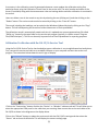
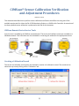
CIMScan® Sensor Calibration Verification
and Adjustment Procedures
(March 17, 2011)
This document describes how to perform sensor calibration verification and offset trim using one of the
available service tools for either the DA-12/16 Monitoring Station or a DA-06 eLink Controller. An overview of
the theory behind sensor calibration is presented at the end of this document.
CIMScan Remote Device Service Tools
A service tool is available for all CIMScan remote devices. The service tool software comes pre-installed on a
Windows netbook. Two USB cables are also included for connecting the netbook to the appropriate device.
Creating a Calibration Record
The service tool software now supports the automatic creation of a calibration record. The record can be
viewed at any time by clicking on the “Calibration” tab.
[1]
A new entry in the calibration record is generated whenever a user updates the calibration setting for a
particular sensor using the Calibration Control Panel in the service tool. The serial number and name of the
sensor (if available) along with the measurement value and settings before and after calibration is contained in
the record.
Users can delete a row in the record at any time by selecting the row (clicking on it) and then clicking on the
“Delete” button. The entire record can also be erased by clicking on the “Erase All” button.
The record, including the headings, can be copied to the Windows clipboard by simply clicking on the “Copy”
button. This will allow pasting the record into a Word document or Excel spreadsheet.
The calibration record is automatically saved each time it is updated to a comma separated text file called
“DACal.csv” located in the same folder as the service tool program (typically in a folder named “Program
Files\CIMTechniques”). This file can be easily imported into an Excel spreadsheet for reporting purposes.
Calibration Verification with the DA-12/16 Service Tool
Using the DA-12/16 Service Tool to check and adjust sensor calibration is very straightforward and easily done.
First, connect the service tool cable to an available USB port on your computer and start the service tool
program. The screenshot below shows the tool’s sign-on display.
Click on the “Connections” button of either the “Station” or “Wireless” indicators ad red. This will allow you to
select the appropriate COM ports for the cable that you are using. Next connect the service tool cable to the
DA-12/16 as shown in the diagram on the display above.
Click on the “Refresh” button to update the service tool with the DA-12/16’s settings and then select the
“Sensor” tab as shown for #3 above. This will display the sensors settings page.
[2]
A precision instrument which has been recently calibrated to NIST-traceable standards should be used to
perform the calibration check and adjustment. Although what will be described here is for a temperature
sensor, the basic procedure is the same for any type of sensor.
The calibration process starts by positioning the temperature probe from the calibration instrument in close
contact with the sensor being calibrated. If the sensor is in a glycol solution, the probe tip should be immersed
in the solution with the sensor. Wait for the measurement on the instrument to stabilize and then follow the
instructions below.
1. Click on the row containing the sensor whose calibration is to be verified and adjusted.
2. Next, click on the “Calibrate” button to display the calibration dialog.
[3]
3.
4.
5.
6.
7.
8.
Make sure that the “Offset Only” checkbox is checked.
Enter the stabilized value on the calibration instrument in the “Desired Value” field.
Click on the “Set” button to associate the “Desired Value” with the “Current Value.”
A new offset value will be automatically calculated and displayed.
Verify that the current value is producing the expected results by clicking on the “Set” button.
Click on the “Submit” button to save the calibration settings and close the dialog.
You can select the “Calibration” tab to make sure that a new entry containing the settings was appended to
the calibration record.
Calibration Verification with the DA-06 Service Tool
Set up the DA-06 Service Tool as described in the DA-06 user’s manual and then select the “Pods” tab. This will
produce the display shown below.
As with the DA-12/16, a precision instrument (standard) is required to perform the calibration check and
adjustment. Again, the following describes the steps for adjusting a temperature sensor, but the basic
procedure is the same for any type of sensor.
The calibration process starts by positioning the temperature probe from the calibration instrument in close
contact with the sensor being calibrated. If the sensor is in a glycol solution, the probe tip should be immersed
in the solution with the sensor. Wait for the measurement on the instrument to stabilize and then follow the
instructions below.
1. Select the Pod to which the sensor to be adjusted is connected. This will display the channel
information for that Pod in the grid at the bottom of the display.
[4]
2.
3.
4.
5.
6.
7.
Select the channel to which the sensor to be checked is attached.
Make sure that the “Offset Trim” checkbox is checked.
Enter the current measurement from the calibration instrument in the “Output” field.
Click on the “Set” button to associate the current “Input” with the “Output” just entered.
A new offset value will be calculated and displayed as shown above.
Click on the “Apply” button to update the calibration settings in the channel grid.
The “Calibration” tab will be displayed whenever Calibration Record contains data. Click on this table to verify
that the record has been updated correctly.
Calibration Report
An Excel spreadsheet is available that can be used to generate a calibration report with the data contained in
the Calibration Record on the service tool. The screenshot below shows the spreadsheet.
You can copy the calibration record from the service tool and paste it into the data area at A10.
Overview of Sensor Calibration in a CIMScan Monitoring System
All sensors or sensor inputs in a CIMScan system can be calibrated in the field by adjusting their scale and
offset values. A typical “CI” series temperature sensor is manufactured to produce an absolute output value in
degrees Celsius. This value is initially multiplied by a scale of 1.000 and an offset of 0.000 is added in the
monitoring station. The calibration scaling can be represented graphically using
simple X-Y chart as shown in the graph. The scale is actually the slope of the line
used to perform the calibration transformation (1 in this case).
Over time, the output of the temperature sensor may change slightly due to the
aging of its components. This change can be detected by comparing the value
produced by the sensor with the output from a precision instrument (calibration
standard) whose probe has been placed in the same environment as the sensor.
The instrument should have been recently calibrated (usually within one year)
[5]
with a standard traceable to the National Institute of Standards and Technology (NIST).
The difference between the outputs from the sensor and the standard (error) may be acceptable, in which
case no adjustment needs be made. If, on the other hand, the value exceeds the limits of error for the
particular application, the scale and offset (calibration factors) for the sensor
must be adjusted. Two types of adjustment are possible. The easiest is to
simply add the error value determined during the calibration check to the
sensor’s offset. This will force the sensor’s output to the value that was
produced by the standard at the value being checked. From then on, all outputs
from the sensor will have this correction added to them. This is called an offset
trim and usually requires about 20 minutes to perform. The chart to the right
shows how and output of 6 is produced with an input of 4 and an offset of 2.
The amount of offset trim can be easily determined using the monitoring
station’s service tool.
In most cases, sensors in a typical monitoring system have alarm limits associated with them. If these limits
are fairly close (±5% of span) to the calibration check value, an offset trim is probably acceptable. If, on the
other hand, measurement accuracy must be maintained across the sensor’s full scale, a 2-point calibration
must be done. This requires the adjustment of both the scale (slope of the calibration curve) and the offset. To
accomplish this, the sensor needs to be removed from its normal environment and placed in a chamber or
other device where the environment can be precisely controlled. A hot and cold bath or the electronic
equivalent is usually used to calibrate temperature sensors. Humidity and CO2 sensors require a chamber that
must be adjustable to two calibration levels. Pressure sensors are usually calibrated utilizing a stable pressure
source and a precision meter. Voltage and current inputs require a calibrator which produces a precision
voltage or current output.
The chambers required for humidity and CO2 sensors are often large; consequently, these sensors are usually
returned to the factory for 2-point calibration. The other sensors can be easily field-calibrated which usually
takes about an hour to an hour and a half to perform. This includes time required to set up the equipment,
remove and reinstall the sensor, and perform the actual calibration.
A 2-point calibration begins by placing the sensor being calibrated in a stable
environment at the lower end of its range. Once the output from the sensor
stabilizes, the environment should be measured with a NIST-traceable
instrument. The user should then enter this value in the “Lower Calibration
Value” box in the station’s service tool and click the “Set” button to acquire the
unscaled value from the sensor. Next, the process should be repeated for the
“Upper Calibration Value.” Once both values have been acquired, the service
tool can be used to calculate both the scale and the offset for the sensor. The
scale is actually the slope of the line between the upper and lower calibration
points and the offset is the value of the Y-axis intercept.
The calibration values for all CI-series plug-in sensors are stored in the sensor itself. These settings are stored
in the eLink when Pods are calibrated.
© Copyright 2011 by CIMTechniques, Inc., 1215 Prince Street, Beaufort, SC 29902
[6]