1
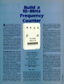
Build a
10 -MHz
Frequency
Counter
A nyone interested
in
high for one second, which prevents
additional input signals from entering
U'. That causes the count latched in U1's
internal counters to be transferred to
the display.
electronics
sooner or later (usually sooner)
needs some sort of test equipment. Almost every electronics hobbyist has a
d gital or analog multimeter, but there
are times when simple voltage, current, and resi stance measurements just
won't do. Sometimes, such as when
working with digital circuits, a frequency measurement is needed. That's the
time when you need an oscilloscope
or frequency counter.
Unfortunately, a low -end oscilloscope or a frequency counter will cost
$ 200 to $ 300, or more; that's more than
many beginning hobbyists want to
spend. Unless, of course, it is a Popular
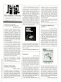
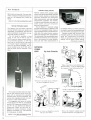
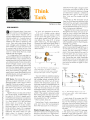
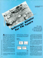
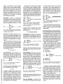
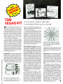
Electronics 10 -MHz Frequency Counter! Built around three integrated circuits, that useful instrument can toe put
together for about $ 40 by anyone who
is reasonably adept at soldering.
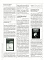
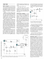
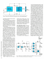
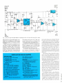
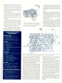
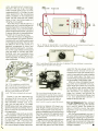
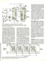
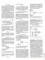
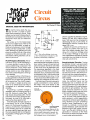
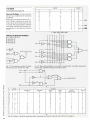
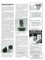
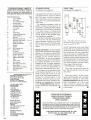
Circuit Operation. Figure shows the
schematic diagram of the 10 -MHz Fre-
f
new
E
1
Hz-IOMHs
FREQ CTR
1111111M111111
Pwa
s
ee
1
quency Counter. The circuit consists of
an ICM7208 seven-decade counter
(U1), an ICM7207A oscillator controller
(U2), ana a CA3130 biFET op -amp
(U3). Integrated circuit Ui counts input
signals, decodes them to 7- segment
format, and outputs signals that are
used to drive a 7 -digit display.
Integrated circuit U2 provides the
timing for U1, while U3 conditions the
input signal to provide a suitable
waveform for input to Ui. The 5.24288 MHz crystal frequency is divided by U2
to produce a 1280-MHz multiplexing
signal at pin 12 of U2. That signal is
input to U` at pin 16 and is used to scan
the display digits in sequence.
The cathodes of each digit are
taken to ground several times each
second, activating any segments of
the digits whose anodes are high as
the result of decod ng by U1. The crystal
frequency Is further divided to pro-
Need a frequency
counter that won't
cost a mine?
This hobbyist -grade
instrument is
just the ticket
for budding techs on a
tight budget!
PAUL AMAN
duce a short "store" pulse at pin 2 of
L2, followec (after about 0.4 milliseconds) by a short "reset" pulse at pin 14
of U2. The frequency of the pulses is
determined by the state of U2 pin 11.
When pin 11 of U2 is taken to ground
through S1, the pulses occur every 2
seconds and cause U2 pin 13 to go
Integrated circuit U2 pin 13 then
goes low for one second, allowing a
new count to be entered into the seven
decade counters of U1. That cycle is
repeated, continuously updating the
display every two seconds.
When U2 pin 11 is taken to the
positive supply rail ( + 5V), the "store"
and "reset" pulses occur at 0.2- second
intervals, resulting in a 0.1- second count period. Ten input pulses must be
counted in order for a '1" to appear on
the first digit, D1, so the frequency
being measured is obviously ten times
larger than the frequency that is shown
on the display.
In that mode, the decimal points are
driven by R1 and visually indicate that
the 0.1- second count period is being
used.
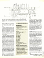
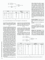
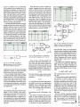
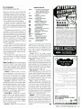
Display. The display must have at
least seven 7- segment common -cathode multiplexed LED digits. Any common- cathode seven -segment display
may be used, so no particular display
is specified. If the display chosen has
more than seven digits, the extras are
rot used. For example, the display
used in the author's prototype, which
was salvaged from an old calulator,
has nine digits, only seven of which are
used in this project.
Don't be put off by the term "multiplexed." Multiplexed simply means
that all like segments of all digits are
connected by a single conductor, and
that the cathodes of all segments of
any one digit are connected to a
common terminal. That's accomplished by a printed circuit within the
display and limits the number of wires
or traces needed to operate the dis-
59