1
48784
JANUARY
1989
Counter
10-MHz Frequency
Build
a
useful addition to your workbench!
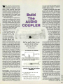
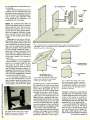
The Audio Coupler
Add an audio input
to your cassette deck!
Strobe
ocket
Find that model rocket,
even at
night or in tall weeds!
Paqer
ersotouc al Pockèt
work, or play wim our
Keep in
build -it-
at home,
urself transmitter/receiver pair!
e Speedi -Watt
Build
It's a light dimmer, a motor
controller, and more!
01
$2.50 U.S.
$2.95 CANADA
o
71
96 4878
3
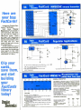
New
FactCards
This Issue
GERNSBACK
8
1111Illllll
q
___
L
C
R
O
P
R
O
A
T
I
_
N
O
1- 800 -344 -4539
I
AR
Punn Roca
TI..
71$ 611T4614
FAX
6262/914
71$
4411
175
TWIt
91035061117 0101 EET CORP
I
1,4 ME IAL OXIDE FILM RESISTORS
I.EE Ti l
]4500
T11
Tom
ACM
3.437/10
.7121
AIM
TOM
04240
270401
741304
071047
Ras
044112.
31
37
3
2
210417.4
20.202,
0NT]P
0043704
07
07
040111
MOM
CV
00300
10010
3
MI
070707
7
0.00
s
PI
10
0.103.1.11
SO
3
AMOY
DOW
S.
WIREWOUNO RFC RESISTORS
i.gp1i
MOW
24040,2
7.111/
22.1211
11.110
301.377
470017
.21:064
04114 Al
00
707
A: 00173110
00300
WY
0074373071
0 00
4105.107
400.171
707531120
310.1311
PANASONIC
700044.00
Y61R'S
4,04
304300
17
0000
7075307
Ml....
747.607
0
5
,
METAL OXIDI EUM RESISTORS
27
3140010
41044077
40541714
20011111
A
AVM
Or
.S1
24
MR.
000030
41000
43
7707107
sl
100707
7/044
040
14
CO
10,07
40
T
40
CO
SO
2310
1710017
0003
411.
011
;11
nt
3103447
10/001
070070
0000
00707
A/D
DIA
I 11101. 00010014107 00070700
30040 0000 407403
moo 307=4 .04141707 0 00
70ta
0424.
OEM
paw
4.141470
11044 40044
171441446, SI
14.000 410100000
0070140,000
NBA
02.20
1022.
074
04007
01212.
TRANS,.
0421011
WO 031112 72 00
moo
0700
NI
ono
770,401
rr
0000
041.022
442.10
04.25
y
04.11.
h~r.s
101117
.00
4R
1
41R
074147
14110
010
0030
70070
0 04
0770,
0070
0 04
00
O
00131
00714
000
20
0037
21
01 AO
;77
PANASONIC LS SERIES
re
.40
10
02 AO
TO
A0
10
2210
7g rari
SRJCON
TRAI55f0Y
20 AO
10 2,70
01170
1040
.0
14120
141120
.0
40 IA
6% CARSON FILM RESISTORS
MO
l
NDwuwewrhi
I
.
r
e
1.4.
w00000
OIR
A,.
.,,.. w,
AAA
r
e
to
4,u,e..e.
ORINMO5 ST NIOSI. CALL
1
", rhe U15
Mu4MU.
woo Sown!
Y
SwO.[am1.04nem.a,444V..M.FP.op+NO.cow.r To
C.n.e..nU M..cu whw, check w..wner w,R. waur.w.r.e.
S5 7444571 IM
FM 710 SRI 55141 ST MAR SISO TODO
0050
or.
w.n..Men
Do eo w+r+.w. u'ew. wn.w. rnr. oro+ouMu 5
10 015 SET PD.
Rl. SI7. MN Oro.
Folk. NS 55711
w.
07
SERVICE CHARGES VOLUME DISCOUNT
NET
AM51 0 0.00-E RI NI
0.54 OJE
F 11.11114111.1111
11{.MId55
1
5,10455
MUDS
CIRCLE 10 ON FREE INFORMATION CARD
700 Ow
UR
AAA
OM
AM sue
AMISS
AN
1
100.5-$25. IS
750.00$45. M
55.00$54.5..
Clow $1056 Up
Lass 104/.
lass 15%
Lass 20%
Less 25%
INCLUDING
12 -PAGE
Volume 6, No.
1
gl'Tun
JANUARY 1989
tYlYNlh'F'l NR/l
Fpu1ar Electronics
CONSTRUCTION
29
34
39
44
59
65
66
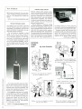
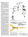
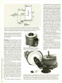
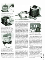
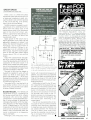
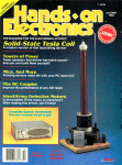
Rocket Strobe -find that model rocket even at night or in tall weeds
Subcarrier Adapter-connects to your FM tuner to uncover hidden FM
transmissions
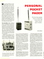
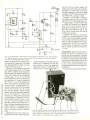
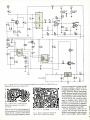
Personal Pocket Pager -keep in touch at home or work with this personal
paging system
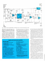
power controller for almost anything electronic
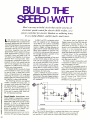
Build the Speedi -Watt
Build a 10 -MHz Frequency Counter -for those times when multimeter
readings just won't do
Build the Audio Coupler-add an audio input to any cassette deck
without modifying the unit
Sound -Activated Kaleidoscope-makes patterns that seem to dance to
the music
Personal Pocket Pager-page 39
-a
Sp>edrWatt -page 44
FEATURES
62
69
GRAPHER.BAS -turns abstract equations into tangible graphs
Salvaging An Autotransformer-they're just as useful today as they were
74
E -Z
yesterday
Math-getting acquainted with Boolean algebra
3IZMO-page
80
HANDS -ON REPORTS
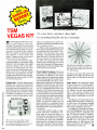
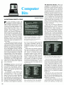
TSM Vegas Kit -for Christmas and
47
all year 'round
SPECIAL COLUMNS
24
82
84
86
88
92
93
Think Tank -SCR projects
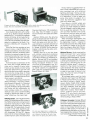
Antique Radio-cabinet refinishing
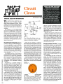
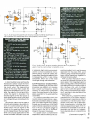
Circuit Circus-unusual uses for transducers
Computer Bits -an electronic Rosetta stone
DX Listening-glasnost and DX'ing
Ham Radio -myths and misinterpretations
Scanner Scene -new frequencies?
Autolransformers-page 69
DEPARTMENTS
2
4
8
16
37
47
71
106
Editorial -adieu Herb Friedman
Letters -the readers speak out
Electronics Library -prepare today for tomorrow's tasks
New Products -what's new in the electronics market
Ant que Radio -page 82
FactCards -the fingertip electronics library
GIZMO Special Section -for the grown -up kid
Free Information Card -get the complete lowdown
Advertising Index-find the products and services you need
/
Scanner Scene -page 93
1
Pp
Popular
o ular Electronics
Adieu Herb Friedman..
.
Herb Friedman has passed away. Herb was the columnist for our computer column.
first met Herb 30 years ago when we both were new to
magazine publishing. was on the job only a week or two
when this huge man filled the frame of my office door. At
first he startled me, but spotted the smile on his face
and a project that he held in his hands. smiled, and that
began a friendship that was never shaken, never encumbered.
I
I
began in 1968 and was ready for the CB boom he
predicted in the early seventies. Herb made it a practice
to test products for magazine reviews only; manufacturers made offers for his service but he turned them
down for fear of compromising his reputation for being
impartial.
I
I
I'll never know how many magazines Herb wrote for, but
I can name a few:
Popular Elec-
tronics, Radio -Electronics, Electronics Illustrated, Radio -TV News,
Electronics World, Elementary
Electronics, Popular Mechanics,
Popular Science, Mechanics Illustrated, Science and Electronics,
Photography, Hi -Fi Stereo Review,
Hi -Fi Stereo Buyers Guide, and
many computer magazines.
I
doubt that anyone has had more HERB FRIEDMAN
freelance articles purchased and
published than Herb.
One of Herb's greatest loves was to sit at his workbench
and produce one- and two- transistor projects that anyone can build in a single evening. As the state of the art
advanced, Herb would build single -chip projects as a
concession to current trends, but he kept the projects
simple. Herb always envisioned a "kid" (as he would call
a teenager) building one of his projects. Thus he was
concerned that the cost was low, the parts were easily
obtainable, and that the circuit was not critical -the
project had to work when powered up.
For many years Herb was in the radio and television
industry. He started out as the technician who lit the fuse
to ignite a pyrotechnic device in an ascending rocket for
the Captain Midnight show in the early fifties. He then
went to Station WNYE at Brooklyn Technical High
School where he spent most of his time at the FM station
as an engineer. Herb enjoyed the inquisitive mind of the
students at the high school, and thus began his freelance writing career so that he could reach out to the
many others who shared the hunger for electronics
project building ideas. When he retired from the radio
station, Herb went to work for Radio -Electronics, our
sister publication, as an associate editor. He was more
than what his title indicated: Herb was an inspiration to
the entire company, especially to the editors of both
magazines. He set up our photographic studio so that
project and product photos would be of the quality re-
quired for our publications.
Herb leaves behind a magnificent family. Nancy, his
wife, is a beautiful person, whose comments from time
to time contributed to the contents of his articles and this
magazine. She is blessed with an uncanny hearing
ability that assisted Herb in rating high -fidelity headphones for many years. Celia, his eldest child in an
accomplished author. Her science -fiction book is a winner. Larry is first entering the business world after an
outstanding college career. He is a superb computer
programmer and has had articles published in several
consumer magazines.
Herb acquired test equipment to build an extensive
consumer -electronics testing laboratory. He did considerable product testing in the seventies and became well
known to U.S.. European, and Japanese audio manufacturers. Many years ago when it was popular to quote
extremely small intermodulation figures, Herb ceased
doing so because he knew once the numbers fell below
a few percent, they were meaningless. The audio industry followed suit a year later.
His private testing laboratory was the first to be capable
of testing citizen -band radios for magazine reviews. He
2
will miss Herb. The entire staff will miss Herb. Our
readers, especially the emerging experimenters, will
miss Herb.
I
Adieu, Herb Friedman.
Julian S. Martin
SELECT 5 BOOKS
HEW TO
TROUBLEShOOT
REPAIR
CI
ELECTRONIC CIRCUIT
j
E
D
for only $3. 95
reel
owl
rourtelter plactu
electroncs
solid& guide t. Acme
Ds it
ál'
SIMPLIF
.
(values to $132.70)
and get a Free Gift!
55.95
2826P
885
516 95
fIBfROPTICS
A
SI
I
1218P
.entary
EIECtricity
Electronics
521 94
2751
$16.95
IA
:\
A I)
It
I
I
B
r i
t
r
F
ELECTRONIC
TABLES 8 FORMULAS
1-III FBIT It) ]
electronics
MATH
+98222
`
4S
,
I
II
I
ill(Ir
1190(81109
c0E1/Af15'AnaS
f
2786
528.95
Counts as
Nwlitr
22 45
1625P
$16.95
le
Owed
19ti-r=---
)LDERLESS
BREADBOARDING
PROJECTS
NASTIER
IC
COOKIOOK
2985
524.95
1199P
518.95
wwww114
CHA NDBOOICR
Beyond the
Transistor
Electronics projects ... ideas ... the latest technology
all at up to 50'1 off publishers' prices
512.95
t:1.>.TEt
RADIO
2887
DESIG111G.
$24.95
1939P
r----
Electronic
Projects From Delton T. Horn
Ikihall'.11m-
15 Easy
Projects you can build -some
unique, some old favorites -from
the author's vast treasury of electronics know-how
.\I l=fimc Paamitc
f{k,-ltnnic Pniecl<
(a $7.95
value!)
$19.95
296C
2910
524.45
1370P
518.95
$26.95
20
S2'.5
29-7
ELECTRONJCS BOOK CHUE
BRIM 1
i
Blue Ridge Summit, PA 17294 -0810
133111 1011111115
SrE11E1S1STI9
,..
Please accept my membership in the Electronics Book Club' and send the 5 volumes listed
below, plus my FREE copy of Delton T Horn's All -Time Favorite Electronic Projects (3105P).
billing me $3.95 plus shipping and handling charges. If not satisfied. may return the books
within ten days without obligation and have my membership canceled agree to purchase
at least 3 books at regular Club prices (plus shipping and handling) during the next 12 months
and may resign any time thereafter.
-.,rr,,,
P
$9.95
for paperback. (Publishers' Prices Shown)
!
s
Handbook
2965
"P"
FREE when you join!
Computer
Technician
1793P
Membership
r988 ELECTRONICS BOOK CLUB'. Blue Ridge Summit PA 17294.0810
516.95
:20.95
2830
Benefits Big Savings. In addition to this introductory
offer, you keep saving substantially with members' prices of up to 50% off the
publishers' prices.
Bonus Books. Starting immediately, you will be eligible for
Club
our Bonus Book Plan, with savings of up to 80% off publishers' prices.
News Bulletins. 14 times per year you will receive the Book Club News, describing all the current selections- mains, alternates, extras -plus bonus offers and
Automatic Order. If you
special sales, with hundreds of titles to choose from.
want the Main Selection, do nothing and it will be sent to you automatically. If
you prefer another selection, or no book at all, simply indicate your choice on the
reply form provided. As a member, you agree to purchase at least 3 books within
the next 12 months and may resign at any time thereafter.
Ironclad No -Risk
Guarantee. If not satisfied with your books, return them within 10 days without
obligation!
Exceptional Quality. All books are quality publishers' editions
especially selected by our Editorial Board.
All books are hardcover unless numbers are followed by a
2801P
$19.95
CErsrlt
EAstrwsd
pysErarw
lol
S
2660P
2
I
I
1964P
$12.95
2900
536.95
Counts as
2987
2
U.1M5 IAI
1RGGEREO
:WEEP
OSCItEOSCOPE
REMOTE
Name
524.95
C0.1fe.Otlt.
OBO
DRIER
Address
i70
City
State /Zip
Phone
Signature
Valid for new members only. Foreign applicants will receive special ordering instructions
Canada must remit in U.S currency. This order subject to acceptance by the Electronics
2853
$23.95
Book Club'
Sgnafure of parent or guardan rebuffed for all new members under l8
RESP- 189
2992
524.95
3
rectly, the "AND" rounding -off works like this:
"F" merely gives you answers without any
rounding off, up to 12 digits; "5/4" should give
rounded -off answers; and "cuT" should enable you to select how many digits you want
behind the decimal point
shouldn't just
limit the user to two, as stated in the article.
S.G.
Caseyville, IL
-it
Letters
Volume 6, No. 1
January 1989
Larry Steckler,
El-4F, CET
Editor -In -Chief & Publisher
ANTIQUE RADIO REVAMP
enjoy reading your column "Ellis on Antique
Radio." Last year, I came across an old table model Emerson 149. The unit was in good
condition, and contained tubes-6A7, 6D6,
607, 25L6, and 25Z5 -and a ballast tube
in a metal case. After cleaning it up, switched
it on. The tubes lit up and there was a low
hum coming from the electromagnetic
speaker.
When I replaced the can filters with two
47 -RF, 150 -volt tubular capacitors, the hum
disappeared; tuning across the band, got
loud whistles. I replaced the screen and AGCbypass caps and joy!-at half volume the
radio came alive with stations. With the tuning at 620 kHz, adjusted the IF can trimmers, and the antenna trimmer on the tuning
condenser at 1400 kHz.
At that point, the radio was just about perfect. There was a slight distortion that
checked with a VOM; found + 12.5 volts
on pin 5, the control grid of the 25L6. Changing the coupling capacitor
.022µF unit that
was also leaking-cured that fault, and the
B + voltage went up by 10 volts.
Now I'm picking up stations from all over
the place with a 9-foot antenna. My advice
to fellow restorers is to change all the paper
and electrolytic capacitors-they always dry
out, leak, or short out.
Can anyone tell me just how old my radio
is? Were they making consumer goods too
good in those days?
H.L.G.
Palm Bay, FL
I
GIVING CREDIT
As many readers know, the authors of the
majority of the articles that appear in Popular Electronics /Hands -on Electronics are
not employees of the magazine. Instead, they
are freelance authors who do the work on
a contractual basis. As part of that contract,
the author warrantees that the work is original, and that nothing contained in the article
violates copyright laws, or any rights of third
parties.
The point of all of that is that in August,
1988 we published an article "50 Years of
Car Antennas" bylined by Edward Janicki.
Mr. Janicki signed our standard contract,
therefore promising that the work was original, and accepted payment for the article.
We have since received word from SAE,
The Society of Automotive Engineers, Inc.,
that the article was taken nearly verbatim
from an SAE paper written by Carlos Altgelt,
Ken Duffy, and Clem Rowan of the Ford
Motor Company. The paper was presented
at the SAE International Congress and Exposition, and was part of an SAE publication titled "Audio Systems for the Automobile." The book and paper were published
and copyrighted on February 29, 1988.
We regret that the rightful authors of that
excellent article were denied the credit they
deserved, and deeply apologize to them and
to the SAE for this unfortunate incident.
Editor
-
I
I
-
I
Art Kleiman, editorial director
Julian S. Martin, KA2GUN, editor
Carl Laron, WB2SLR, managing editor
Robert A. Young, associate editor
Herb Friedman, W2ZLF, associate editor
John J. Yacono, associate editor
Brian C. Fenton, associate editor
Byron G. Wels, K2AVB, associate editor
Teri Scaduto, assistant editor
Kathryn Campbell, editorial assistant
Ruby M. Yee, production director
Karen S. Tucker, production manager
W. Lowndes, editorial
associate
Marcella Amoroso, production assistant
Andre Duzant, technical illustrator
Injae Lee, assistant illustrator
Jacqueline P. Cheeseboro, circulation director
Nancy Estrada, manager, HOE Bookstore
Robert A.
I
BUSINESS AND EDITORIAL OFFICES
I
Gernsback Publications, Inc.
500-B Bi- County Boulevard
-a
Farmingdale, NY 11735.
516/293 -3000
President: Larry Steckler
Vice- president: Cathy Steckler
Cover photography by
Diversified Photo
Services
Composition by
Mates Graphics
Advertising Sales Offices listed on page 106.
SNIFFING AROUND
SORRY, WRONG NUMBER
We have learned that the toll -free number
given in the review of the "Digital Voice Record/Playback Module" in the October 1988
issue was incorrect. The correct number for
the kit's distributor, the Tapto Corporation,
is 1 -800- 876 -8001.-Editor
CASIO CLARIFICATION
"Gizmo,"
the review of the Casio JE -3 desk -top calculator contains some terms-"AND," "F," "54,"
and "cuT"-which were foreign to me at first.
Casio is my favorite manufacturer, and I wish
still had my old FX-21 with the blue nixie tube display. I'll buy the batteries rather than
strain my eyes on most LCD displays.
In any case, if I understand Casio corIn the September 1988 installment of
I
4
would like to thank you for providing a great
magazine geared toward the hobbyist. I particularly enjoyed building the "RF Sniffer" in
the August issue. However, there are some
errors in it. LED should be labeled as LED
2, and vice versa; L2 is correctly stated in
the parts list to be a 2 -mH choke, but the
schematic shows it as a 2 -RH choke.
Speaking of RF chokes, I would like to
see some information on how to read the
molded kind. Are they color coded and read
the same as resistors? They seem to have
more color bands than resistors do. Are they
read as microhenry or millihenry?
Incidently, to make the "RF Sniffer" more
sensitive, replace the telescoping antenna;
cut an 8-inch length of 75 -ohm coax; and
remove the vinyl sleeve, the outer braid, and
the center conductor wire so that all that is
11Rí
I
1
e
3
Handson Electronics including Popular Electronics, (ISSN
0743-2968) wished monthly by Gernsback Publications. Inc
500 -e Br- County Boulevard. Farmingdale. NY 11735 Second Class postage paid at Farmingdale. NY and al additional mailing
offices One -year. t eNe issues. subscnptnn rate U S and possessions S21 95. Canada $26 95. all ocher counlnes S29 45 Subscnptan orders payable in U S funds only. International Postal Money
Order or check drawn on a U S bank. U S segle copy pace S2 50
1988 by Gernsback Pudnatnns, Inc M rghls reserved. Hands on Electronics and Glary trademarks are reentered on U S and
Canada by Gernsback Publications. Inc Popular Electronics
trademark is registered in U S and Canada by Eleclronres Tech.
nology Today 'rd is licensed to Gernsback Publications Punted in
.
USA
Postmaster Please send address charges to Hands-On Electronics, including Popular Electronics, Subscnptan Dept P o
Boa 338. Mount Morns. IL 61054 -9932
.
stamped self addressed envelope must accompany all sublndted
manuscnpts and or arhrork or photographs it their return is dewed
should they be rejected We disclaim any responsibility for the loss
or damage d manuscrpts and or artwork or photographs while in
our possession Of otherwise
A
Harrison Electronics including Popular
Electronics publishes available plans or information relating to
As a service to readers.
newsworthy products. techrkees and scientific and technological
developments Because of possibly vanances in the quality and
condtnn of malenals and workmanship used by readers. Hands on Electronics rncludng Popular Electronics disc-laws any responsibility lo" the sale and proper lunctnrwg d reader buy projects based upon or from plans or mlormalnn published in this
magazine
have a Dumont handheld FM radio receiver:
type DH300, Model N33H, from Ham marlund Mfg. Co., Inc. in Marshill, NC. I've
written to that company, but didn't get an
answer. Can anyone help me find a schematic diagram and any other information on
that receiver?
Ernest Wurfer
741 San Diego Ave.
Sunnyvale, CA 94086
left is the dielectric material. Wind the entire
length with No.26 wire, close wound, and
solder it to a male pin connector attached
on one end. Cover the length with heat shrink tubing. You now have a flexible antenna that is much more sensitive than
I
it is a
I
the telescoping kind. Attach the female
pin connector to the case, and it becomes
removable.
M.B.
MC14515." That is far from the truth. To make
the data complete and true, it should include
the 4515. That is because, according to
specs, when the chip is selected the output
of the 4514 goes HIGH and when the 4515
is selected the output goes LOW. Its something like saying that they are the same breed.
but different sexes.
C.R.D.
Aurora, CO
Van Nuys, CA
Perhaps you can help me. just recently got
my hands on a Lewytt RC77 GRC9 U.S. Army
Corps Field Radio with no manual. It's a transceiver tube-type radio: I'm not sure how old
it is. I'm looking for the correct operating voltage, and, of course, a manual for it.
I
Molded chokes do share their color -code
scheme with resistors, although there are
some differences in the way the two are read.
For exact information on how to read molded
chokes, see the ARRL Handbook's chapter
on Construction Practices and Data Tables;
if you don't own a copy of the Handbook,
one is available at most local libraries. Also,
a FactCard on inductors, including RF
chokes, is planned for later in the year.
Andrew Bowlby
4700 Highland Ave.
Downers Grove, IL 60515
A SIZABLE MISTAKE
While building the "Speech Processor" from
the October 1988 issue of Hands -on Electronics, discovered that the board size is
wrong. First. made a transparent copy at
53 4- inches as the article said. Following the
parts -placement diagram, aligned each chip
over the corresponding chip diagrams. But
my copy-that complied with the directions
in the article -was too big! reduced the size
from 53 4- inches to 45 8- inches, and everything lined up correctly.
I
I
I
I
CHECK YOUR FACTS
Having just purchased my first copy of Popular Electronics, can truthfully say that it
seems to be a good publication for anyone
who enjoys working or playing in electronics.
I'm writing to point out some information
S.P.
I
HAVES AND NEEDS
recently purchased a used Bearcat 300 scanner. The instruction manual was missing. Can
anyone advise me on where to find one ?.
Ron Fite
1205 East 25th St.
San Bernardino, CA 92404
I
that is inaccurate due to the omission of some
data. "FactCard 85," concerning the 4514
IC, states in "Features" that the 4514 is a
"Plug -in replacement for MC14514,
Chicago, IL
You are correct. Due to a reproduction error, the board that was prepared for publi-
cation, and measured for the article, was
roughly 20% oversized. The proper dimension is indeed 45/8 inches.
SPEAKERS AND COMPONENTS
í PIONEER
l^^
MOTOROLA
6" x 9" COAXIAL SPEAKERS
Super buyout. Made in Japan by
Pioneer for GM. Upgrade auto sound
system. 6" x 9" woofer, 2'6" cone
tweeter. 35 watts RMS. 50 watts max. 12
oz. magnet, Dust cover. Sold in pairs. 8
lbs. /pair. Limited quantities.
$1195
$14$0
#300-220
(1 -5
(6 Drs -up)
pm)
iii0
100 WATTS
RMS
PIONEER
100 WATTS
RMS
12" POLY WOOFER
Super duty. 40 oz. magnet Polypropylene
cone 100 watts RMS. 145 watts max. 4 -8
ohm compatible (6 ohm) 2" voice cod
$2870
#290-125
(4 -up)
(1-3)
$3680
$3450
,1.3)
)4 -up)
12" 3 -WAY, 100 WATT SYSTEM
15" WOOFER
60 watts RMS, 90 watts max 1½" voice
coil. 8 ohm, 25 -2500 Hz response. 20 oz.
magnet, paper cone with poly foam
surround. 93 dB, 1W/1M sensitivity. Net
weight
7
lbs.
$2895
Any 0ly
#290 -160
WOODGRAIN
GRILL CLOTH
#260 -340
$595
System Includes (1) #290-125 poly
woofer, (1) #280 -045 heavy duty 5'.'
midrange. (1) #270-035 4" son dome
tweeter. (1) #260- 210 3 -way 100 watt
crossover. (2) #260-255 50 watt Lads.
(1) #260 -300 terminal. and (1) #260-340
woodgram grill cloth Recommended cabinet volume
Cu ft Cabinet Kit Available 8260 -390 $19.95 each
per Yard
v
t
#12 -100
Save Over
E First St, Dayton, OH 45402
Local -513- 222-0173
340
1
1- 800 -338 -0531
100 oz magnet. 3" voice coil 250 watts
RMS. 350 watts max. 8 ohm, 30 Hz
resonant frequency, 22-2700 Hz
response. Efficiency. 95 dB, W /1M.
Paper cone treated accordian surround
Net wt 291bs.
1
4200 -200
(V)
$8950
$9880
)4 -up)
PIONEER
Exponential horn design.
Mylar dome. 3'," o 3'h"
1800-20.000Hz response
35 watts RMS. 50 watts
max
$590
$650
#270 -050
I
3
1pupi
3-WAY 100 WATT
1
$7395
CROSSOVER
12
dB /octave rolloft. 800
Hz, 5000 Hz. 8 ohm 100
watts RMS.
#260-210
$1000
CALL
TOLL FREE
Made in
U.S.A.
HORN TWEETER
Pioneer design engineers carefully
evaluated the performance characteristics of this speaker systems to ensure
the best full range frequency response
Authentic woodgrain print
design cloth. 36" o 60"
EMINENCE
-*OW"
18" WOOFER
MADE IN
U.S.A.
10" WOOFER
$3150
ENPIFE
EMINENCE
Super duty 34 oz. magnet, 2" voice coil.
Paper cone, treated accordian
surround. 100 watts RMS. 140 watts
max. 8 ohm, 70Hz resonant frequency,
response 45 -4000 Hz Net weight. 8lbs.
#290 -098
0,0
EtIECTxaaICS
EMINENCE
15 day money back guarantee.
$10.00 minimum
order. We accept Mastercard, Visa, Discover, and
C.O.D. orders. 24 hour shipping.' Shipping charge
UPS chart rate ($2.50 minimum charge). Hours:
8:30 am - 6:00 pm EST, Monday - Friday. Mail order
customers, please call for shipping estimate on
orders exceeding Slbs.
FAX 513 222 -4644
CIRCLE 16 ON FREE INFORMATION CARD
$995
$1250
r.,.
-
FREE
CATALOG
5
413 JDR Microdevices®
30 DAY MONEY BACK GUARANTEE
COMPLETE CUSTOMER SATISFACTION
SIZE
256x4
1024x4
1024x4
2048x8
2048x8
204818
2048x8
2048x8
2048x8
2048x8
2048x8
2048x8
21141,2
TC5516
1M142016-200
1MM2016.150
1MM2016- 100
HM6116-4
HM6116.3
HM6116-2
HM6116LP-4
HM6116LP-3
SPEED
450ns
450ns
200ns
250ns
200ns
150ns
100ns
200ns
150ns
120ns
200ns
150ns
120ns
2048:8
HM6264LP-15
8192x8
HM6264LP-12
8192:8
HM43256LP-15 32768:8
HM43256LP-12 32768E8
HM43256LP-10 32768x8
11M6116LP-2
DART
4116 -200
4116 -150
PRICE
219
99
1.49
3.95
3.25
MK4332
4164-150
4164-120
4164 -100
3.29
4.29
4.95
5.95
150ns
120ns
150ns
120.5
1000s
1554164
TMS4416
41128 -150
645
TMS4464.15
5.95
6.45
6.95
9.95
1095
12.95
14.95
TMS4464 -12
41256 -150
41256 -120
41256-100
41256 -80
HM51258.100
MB -120
MB -100
1995
163840
200115
16384 x1
150115
327680
131072x1
65536E4
200ns
150ns
12005
100ns
15005
150ns
150ns
150ns
655360
120115
6553601
65536:1
65536:1
655360
16384:4
262144/1
15005
120ns
10005
262144x1
80ns
262144,1
10005
12005
1000s
262144x1
2621440
1048576x1
10485760
CALL TO CONFIRM CURRENT
CALL TO CONFIRM CURRENT PRICES
EPROMS
PRICE
PART
SIZE
1024:8
2708
2716
204828
2716 -1
2048.8
4096E8
2732
4096:8
2732A
27C64
8192:8
2764
819208
2764-250
8192:8
2764-200
819218
MCM68766
8192x8
1638403
27128
271288-200 16384x8
27C256
32768x8
27256
32768x8
27256-200
32768x8
27512
655360
27C512
65536:8
27C101.20 13107208
89
99
6.95
2
89
3
19
3.95
2.89
8.95
5.95
10 95
11.95
12.45
12.95
13.45
13.95
13.95
34.95
37.95
8000
6502
6502A
2 25
8031
3
2.69
6502B
65CO2'
4.25
8035
8039
149
195
6520
6522
6522A
6526
6532
5.95
65454
3
6551
2.95
6551A
6 95
95
'CMOS
34 95
249
1
8742
6800
1.95
68809
599
6809E
2.95
5.49
295
3.95
2.95
68809E
8749
8755
80286
80286.8
6.49
599
1295
7.95
2.49
2.95
395
995
75
2295
8251A
95
1
2.95
1.25
85
3.95
2.75
1
68845
495
6847
6850
4.75
195
68850
1
68000
9
95
29 95
7 95
9 95
14 95
79 95
249 95
8200
8205
8212
8216
8224
8228
8237
8237-5
8238
8243
8250
8251
6810
6820
6821
68821
6840
6845
95
375
8741
6800
6802
6803
6809
95
805289
BASIC
8080
8085
8085A -2
8086
8088
8088-1
8088-2
8155
8156
8155 -2
8200
8253-5
8254
8255
8255 -5
8256
8259
8259-5
8272
8274
8275
8279
8279-5
8282
8283
8284
8286
8287
8288
1.95
2.79
1.S9
15.95
195
69
1.09
1.95
.59
.99
1.49
.34
LM309K
LM310
1.25
1.75
.59
134311
LM311H
.89
LM31IK
LM3129
3.49
LM317T
LM318
LM319
LM323K
LM324
LM331
LM334
LM335
LM336
LM338K
LM339
LF347
LF353
LF356
1F357
LM358
1.75
.69
1.49
1.25
349
34
395
1.19
1
1
79
75
4.49
59
219
59
99
99
59
LM380
LM383
LM386
LM393
LM394H
LM399H
TL494
TL497
NE555
NE556
NE558
NE564
LM565
LM566
LM567
NE570
NE590
NE592
LM723
LM733
LM741
LM747
MC1330
MC1350
LM1458
LM1488
LM1489
LM1496
ULN2003
123V
125V
715
515
10
80287
80287 -8
80287 -10
80387-16
80387-20
80387 -25
10
16
6
8
20
25
99.95
MHz
MHz
MHz
MHz
MHz
MHz
MHz
MHz
MHz
159 95
229 95
179 95
249
309
499
799
999
95
95
95
95
95
intel
5
12.5V
7.95
11.95
12.5V 12.95
12.5V 34.95
YEAR
125V
WARRANTY
INCLUDES MANUAL 8 SOFTWARE GUIDE
S
A
2 25
395
Z80-CPU
21304-CPU
1.25
1.29
1.69
1.29
1.69
59
7130A DMA
5.95
I 89
425
5.95
12.95
5.95
0
0
1
Z80A-5102 595
2808-SIO 2 12 95
Z8671BASIC 995
89
195
89
45
595
95
20
325
29
49
79
95
95
49
79
2.95
2.50
98
49
98
29
69
69
1
1
119
35
49
49
85
79
XR2206
XR2211
LM2917
CA3046
CA3146
MC3373
MC3470
MC3480
MC3487
LM3900
LM3909
LM3911
LM3914
LM3915
MC4024
MC4044
RC4136
RC4558
LMI 360
75107
75108
75110
75150
75154
75188
75189
75451
75452
75477
95
2.95
1.95
89
29
29
95
1
1
1
895
295
2
1
1
49
98
25
89
89
r
69
49
49
49
95
95
1.95
1.25
25
39
39
29
1
1
1
1
2.95
1698
1696
1684
2
1
49
49
49
09
59
59
59
59
59
139
69
49
49
1
1
49
69
49
3 49
1
4
49A
MISCELLANEOUS
ADC0804
ADC0809
DAC0800
DAC0808
DAC1022
MC 1408L8
8128
8T97
6...P8304
2.99
3.85
3.29
1.95
5.95
95
29
59
2 29
I
1
9334
9368
9602
ULN2003
MAX232
MC3470
MC3487
175
2.85
69
79
7.95
95
1
295
455.3600
PRO
11
95'
95
2.95
2.95
UARTS
AYS-1013
AY3-1015
TR1602
2651
3.95
895
3.95
4.95
IM6402
IM6403
315
11458250
615
NS16450
9.95
1015
INTERSIL
ICL7107
ICL7660
ICL8038
ICM7207A
ICM7208
1095
1.99
3.85
5.95
15 95
74LS05
74L508
74LS09
74LS10
74L511
741.512
74LS13
74LS14
74LS15
74L S20
74LS21
74L522
74LS27
74LS28
74LS30
74LS32
74LS33
74LS37
74L538
701.542
74LS47
74LS48
74L551
74LS73
74L574
74L575
74L576
74LS83
74LS85
74LS86
74LS90
74LS92
74L593
74LS95
74L5107
74LS109
16
18
74LS112
.17
.18
16
.18
74LS123
29
45
49
74LS1 24
275
74LS125
74LS126
74LS172
74L5133
74LS136
74L5138
74LS139
74LS145
74LS147
39
39
39
49
39
39
39
99
99
99
39
39
49
59
49
35
29
29
39
18
18
16
22
22
26
39
26
17
22
.22
23
26
.17
.18
.28
.26
.26
39
.75
85
.17
.29
24
29
29
49
49
22
39
49
39
49
34
36
74LS1 22
741.5148
74LS151
74LS153
74LS154
74LS155
74LS156
74LS157
74LS156
74LS160
74LS161
74L5162
74LS163
74LS164
74LS165
74LS166
74LS169
741.5173
49
39
49
65
95
95
49
39
39
49
69
69
69
69
59
59
59
69
74LS1 74
741.5175
74LS191
74LS192
74LS193
74LS194
74LS195
74LS196
74LS197
74LS221
74LS240
74LS241
74LS242
69
69
69
69
79
49
49
39
49
74L5243
74L5244
74L5245
74LS251
74L S253
74L5257
74L5258
74LS2S9
74LS260
7ALS266
74LS273
74L5279
74LS280
7415283
74L5290
74LS293
74LS299
74LS322
74LS323
74LS365
74LS367
74L5368
74L5373
74L5374
74L5375
74LS377
741.5390
74LS393
74L 5541
74L5624
74L5640
74LS645
74LS670
74LS682
74LS688
74L5783
25LS2521
26LS31
26LS32
129
49
39
79
39
98
59
89
89
49
3.95
1
249
39
39
39
79
79
95
79
19
79
49
95
99
99
89
1
1
1
320
2.40
22.95
2.80
1.95
195
HIGH SPEED CMOS LOGIC
74HCD0
74HC04
74HC08
74MC14
74HC32
74HC74
74HC138
74HC 139
7/HC154
7AHC157
74HC161
70HC164
L.74HC175
21
25
25
35
35
35
as
1
45
09
55
65
65
59
74HC244
74HC245
74HC273
74HC367
74HC373
74HC390
74MC374
74HC4040
74HCT00
74HCT04
74HCTOB
7aHCT32
74HCT74
85
85
69
69
69
79
69
.89
25
27
25
27
OS
7AHCT138
74MCT139
74HCT157
7AHCT161
74HCT240
74HCT244
74MCT245
74HCT273
74HCT373
74MCT374
74HCT393
74HCT4040
74HCT4060
.35
.55
.59
79
89
.89
.99
.99
99
99
99
99
1.49A
1
STANDARD CMOS LOGIC
99
125
16L8
7812K
7905K
7912K
78L05
78L12
79L05
79L12
LM323K
LM338K
7805K
349
3
REGL/LATORS
78057
7808T
7812T
7815T
7905T
79087
79121
7915T
r
3
PALS
VOLTAGE
3
275
6.95
SERIES
HIGH SPEED ADDRESS CALCULATION IN HARDWARE
PIN COMPATIBLE WITH 8088
SUPERSET OF 8088 INSTRUCTION SET
LOW POWER CMOS
V20'
5 MHz
V20'
10 95
895
8 MHz
10 MHz 1295
V20'
V30
13.95
8 MHz
395
95
4 95
741,500 TTL LOGIC
74LS00
74LS01
74LS02
74L503
SPEED UP YOUR PC BY 10 TO 40%
2.95
3.95
4.25
280B-CTC
2804-DART S.95
2808-DART 6.95
95
V-20
r
249
Z80ACTC
4.49
Ì
4001
4011
4013
4015
4016
4017
4018
4020
4021
4023
4024
4025
4027
19
19
35
29
29
49
69
59
69
25
49
25
39
4028
4040
4042
4044
4046
4047
4049
4050
4051
4052
4053
4060
4066
69
4069
4070
59
4081
69
69
69
4093
65
29
29
69
69
69
69
29
.19
29
.22
49
14411
9.95
14433
14497
4503
4511
4518
4528
4538
4702
14.95
6.95
49
69
85
79
95
9.95,
J4no
7400
7402
7404
7406
7407
7408
7410
7411
7414
7416
7417
7420
7430
7432
7438
7442
7445
7447
7473
7474
7475
7476
7483
7485
7586
7489
7490
7493
19
19
19
29
29
.24
.19
25
.49
.25
.25
19
19
29
29
49
69
89
34
33
45
.35
.50
.59
.35
2.15
.39
35
74121
74123
74125
74150
CIRCLE 12 ON FREE INFORMATION CARD
1
74151
74153
74154
74157
74159
74161
74164
74166
74175
74367
29
49
45
35
55
55
149
55
1.65
69
85
00
89
65
1
J4FiJ4 S
>4F00
74F02
74E04
74E08
74E10
74E32
74E64
74E74
74E86
70138
74F139
74E253
74E157
JDR MICRODEVICES AND THE JDR MICRODEVICES LOGO ARE REGISTERED TRADEMARKS OF JOR MICRODEVICES. 18M, AT. PS/2 ARE TRADEMARKS OF INTERNATIONAL BUSINESS MACHINES.
6
8
4.25
21V 15.95
12.5V 4.95
12.53/
5.95
74LSO4
4.95
16.95
Z-80
280A-PIO
Z80B-P10
Z80A-SIO
2808-SIO
Z80A-SIO
lí49.95
MCT -SCSI
439
7808-CPU
475
5
4
3.69
5
80871
TOLL -FREE TECHNICAL SUPPORT
COMPATIBLES
THAT CAN CONTROL UP TO SEVEN SCSI DEVICES THIS
POPULAR STANDARD OFFERS SPEED. EXPANDABILITY AND
THE ADVANTAGES OF USING A DEVICE INDEPENDENT BUS
INCLUDES CABLES
2.29
LINEAR COMPONENTS
TL071
TL072
T1074
T1081
TL082
TL084
LM301
12.5V
12.5V
8087
8087.2
30 OAY MONEY-BACK GUARANTEE
149
49
49
2.25
2.25
3.95
1
8253
200115
A LOW POWER. SHORT SLOT CARD FOR PC
329
1
20000
35000
250ns
20005
25000
250ns
20005
25005
2500$
CALL TO CONFIRM CURRENT PRICES
PRICES
SCSI HOST ADAPTOR
7.95
1.65
2 95
5 95
13.95
25Ons
NIGH-TECH
SP i TLICI' T
MICROPROCE550R5
6500
CO- PROCESSORS
SPEED
Vpp PRICE
45005
25V 415
45005
25V
3.49
350ns
25V
3.95
450ns
25V
3.95
2500s
21V
3.95
2500s 12.5V 4.95
450ns 123V
349
L.
CALL FOR VOLUME QUOTES
ORDER TOLL FREE
r
SPEED
SIZE
TOLL -FREE TECHNICAL SUPPORT
FRIENDLY, KNOWLEDGEABLE SALES STAFF
SUPERIOR SERVICE
DYNAMIC RAMS
STATIC RAMS
PART
2112
2114
YEAR WARRANTY ON ALL PRODUCTS
1
35
35
35
35
35
35
55
39
55
.79
.79
89
89
74E240
74500
74502
74504
74508
74510
74532
74574
74586
745112
745124
745138
745153
745157
745158
745163
745175
745195
745240
745241
745244
745280
745287
745288
745299
745373
745374
745471
745571
1
29
29
29
29
35
.29
35
49
.35
50
275
79
79
79
95
29
79
49
49
49
49
95
69
69
2.95
69
1.69
1
495
295
CRYSTALS
32.768 KHz
1.0
MH:
16751
165402
944004
164148
KBP02
PN2222
2N2222
2N2907
2N3055
1.8432
2.0
2.4576
3.579545
4.0
1.95
1.95
1.95
101.00
251.00
12.0
14.31818
1.95
16.0
18.0
1.95
1.95
TANTALUM
18.432
20.0
22.1184
1.95
1.95
1.95
1.0yí
5.0688
6.0
6144
8.0
10.0
10.738635
5.95
5.95
5.95
5.95
4.95
5.0
4.95
4.95
4.95
4.95
4.95
4.95
4.95
5
0688
6.0
6 144
80
10.0
12.0
14 31818
15.0
16.0
6.8
10
22
1.Opf
2.2
4.7
10
lOpf
22
33
47
100
220
001yf
005
01
05
1
1
9.95
4.95
9.95
COM5016
COM8116
MM5307
1695
ADJUSTABLE HEAT SETTING
R
TIP TEMPERATURE READOUT
REPLACEMENT TIPS
AVAILABLE 02.95
FR
4
EPDXY GLASS LAMINATE WITH GOLD PLATED EDGE
CARD FINGERS AND SILK SCREENED LEGENDS
68-2C
1
.59
1.29
99
71L-111
15V
15V
15V
15V
12
35V
35V
35V
19
39
RADIAL
1,4
42
.45
.99
35V 45
14
50V
11
50V
11
50V
35V
13
15
16V
50V .23
35V 20
25V
30
16V .70
25V 1.45
47
10
47
100
100
220
69
470
2200
4700
50V
50V
50V
50V
50V
50V
50V
50V
50V
50V
12V
50V
05
05
05
.05
05
.05
.05
.05
.07
07
.10
50V
22
47
100
50V
35V
470
R
50V
16V .29
16V 70
16V 1.25
1000
2200
4700
12
0155
.0155
1
1
895
495
a5
a5
MC146818
MM58167
CERAMIC DISC
MONOLITHIC
CERAMIC DISC
MONOLITHIC
.
;A .12V @ 3A
PS-1558
.
(V
I
.11
5A
.12 501
PS-1554
4.95
9.95
9.95
1793
1795
1797
2791
2793
995
2 95
FEMALE - FEMALE 7.95
MALE-MALE
7.95
MALE -FEMALE
7.95
NULL MODEM
8.95
GENDERJB JUMPER BOX
8.95
GENDER -MT MINITESTER
14.95
Jt
529.95
524.95
"SNAPABLE"
DISK CONTROLLERS
1771
1791
534.95
GENDER -FF
GENDER -MM
GENDER -MF
GENDER -NM
Ill APPROVED 144 WATT
-5V @ 18A .12V @ 4A
2V @ 500MA
A
IF
12V @ 250MA
MICRO SUPPLY
I..
25A
!H
PS-ASTEC
100 5.00
100 10.00
100 6.50
100 12.50
CLOCACIRCL/IT9
5.95 MM58174
9.95 MSM5832
Sag 95
FLOPPY DRIVE SUPPLY
34.95
12.95
DECODING LAYOUT
GENGER CHANGERS
5V @ 300MA
PS-A
O
27.95
WITH 5V AND GROUND PLANE
AS ABOVE WITH 110 DECODING LAYOUT 29.95
Ill APPROVED
5V @
.14
.14
.16
.14
.19
.19
.29
16V
50V
16V
I
FOR JDR PR10 ABOVE
FOR XT
75 WATT SUPPLY
A,
f
10
10
FOR AT
16BIT WITH
JDR -PR10
JDR-PR1OPK PARTS KIT
POWER SUPPLIES
AXIAL
I
I
IBM -PR1
18M -PR2
APPLE TYPE SUPPLY
69.95
49.95
15.95
39.95
JDR -PR32
32 BIT PROTOTYPE CARD
16 BIT WITH O DECODING LAYOUT
JDR -PR16
JDR- PR16PK PARIS KIT FOR JOR -PR16 ABOVE
JDR -PR16V 16 BIT FOR VIDEO APPLICATIONS
FULL 1 YEAR
WARRANTY ON
EVERY PRODUCT!
ELECTROLYTIC
REPASS CAPACITORS
BIT RATE
GENERATORS
MC 14411
BR 1941
4702
10
10
25
DISC
4.95
4.95
4.95
4.95
20.0
24.0
4N28
4N33
4N37
MCT-2
MCT-6
25
79
R
FOR PS 2
1.95
1.95
18432
4626
4627
APPROVED
uI
CAPACITORS
OSCIE LA LORS
1.0MH:
5.95
1.8432
2.0
2.4576
2.5
4.0
TIP31
10
263904
263906
264401
25
75
40
.49
.69
69
.69
.89
1.10
1
MPS -A13
.55
.10
1.95
1.95
1.95
1.95
1.95
1.95
1.95
1.95
1.95
5 0
264403
266045
49
25
WIREWRAP
PROTOTYPE CARDS
SOLDER STATION
DISCRETE
.95
2.95
2.95
2797
8272
UPD765
MB8876
MB8877
12.95
12.95
19.95
39
1295
12.95
6.95
6.95
1691
19.95
2143
BREAKOUT BOX
CAN BE SNAPPED APART
TO MAKE ANY SIZE HEADER,
ALL WITH .1" CENTERS
4.39
4
RS -232
HEADERS
29 95
1540
1540
2540
2540
STRAIGHT LEAD
RIGHT ANGLE LEAD
2 STRAIGHT LEADS
2 RIGHT ANGLE LEADS
FOR TROUBLESHOOTING
SERIAL COMMUNICATIONS
.49
2.49
2.99
OPEN CLOSE INDIVIDUAL CIRCUITS
20 JUMPERS CROSS -CONNECT ANY
TWO CIRCUITS
10 LEDS SHOW CIRCUIT ACTIVITY
GENDER -BO
534.95
IDO CONNECTORS /RIBBON CABLE
5ESCRIPTION
CONTACTS
ORDER BY
28
34
40
.82 1.29. 1.68. 2.20. 2.58
.85 1.35. 1.76. 2.31. 2.72
1.86 .298 .3.84. 4.50. 5.28
2.05 3.28 .4.22 4.45. 4.80
.63
.89 .95. 1.29. 1.49
- 5.50 6.25 7.00 7.50
85 1.25 1.35 1.75 2.05
1.60 3.20 4.10 5.40 6.40
10
SLIDER HEADER
RIGHT ANGLE SOLDER HEADER
WIFEWRAP HEADER
RIGHT ANG _E WIREWRAP HEADER
RIBBO4 HEADER SOCKET
RI IBON HEADER
RIBBON EDGE CARD
10' PLASTIC RIBBON CABLE
IDHaaS
IDHYYSR
IDHXaW
IDH55WR
IDSXa
.
20
.
.
.
IDMu
IDE55
RC.
50
.
.
.
3.24
3.39
6.63
7.30
1.69
8.50
2.45
7.50
Model
FOR ORDERING INSTRUCTIONS. SEE DSUBMINIATURE CONNECTORS BELOW
SOLDE
CUP
RIGHT INGLE
PC SOLDER
WIREWRAP
IDC RIBBON CABLE
HOODS
!intensity Unit
01
Chips (uW Cm') Cost
9
9
12
8.000
8.000
9.600
0 89
0139
$189
SET X V AXIS FOR AUTO CENTER
OR FREE MOVEMENT
FIRE BUTTON FOR USE WITH GAME
SOFTWARE
COMPATIBLE WITH IBM, APPLE II.
III. IIC, ATARI 8 VIC 20,64
GC-10
.1995
CONTACTS
ORDER BY
MALE
FEMALE
MALE
FEMALE
MALE
FEMALE
MALE
FEMALE
METAL
PLASTIC
Timer
PE -140
NO
PE -140T YES
PE -240T YES
D-SUBMINIATURE CONNECTORS
CE SCRIPT ION
JOYSTICK
EPROM ERASERS
SPECTRONICSCORPOR4TION
DBnP
DB55S
9
15
19
45
.49
59
.69
69
.75
25
.69
.75
37
1.35
1.39
50
1.85
3.89
6.84
2.25
2.35
5.60
9.95
4.25
4.49
-
1.25
.39
--
-
.69
.75
2.29
DBxPR
DBaSR
OATARASE
1.69 296
2.76 4.27
1.39 1.99
DBaSPWW
DB555WW
IDBSaP
IDBSaS
MHOODaS
HOODaS
1.45
1.05
.39
-
205
1.15
.39
1.25
--
34.95
ERASES 2 EPROMS IN 10 MINUTES
VERY COMPACT NO DRAWER
METAL SHUTTER PREVENTS
UV LIGHT FROM ESCAPING
-
ORDERING IP.WTRUCTIONS:
INSERT THE A.UMBER OF CONTACTS IN THE POSITION MARKED -a. " OF THE -ORDER BY"
PART NUMBEd LISTED EXAMPLE A 15 PIN RIGHT ANGLE MALE PC SOLDER WOULD BE
DBISPR
MOUNTING HARDWARE 591
C SOCKETS /GIP CONNECTORS
DESCROTION
8
SOLDER'/
IL
SOCKETS,
WIREWRA ' SOCKETS
ZIF SOCKETS
TOOLED SOCKETS
TOOLED WW SOCKETS
COMPONENT CARRIERS'
ssST
asWW
21F1í
AUGATsST
AUGAT55WW
ICCax
LITHIUM BATTERIES
CONTACTS
ORDER BY
14
.11
.59
-
16
12
.15
69
69
4.95 4.95
.62
79
1.30 1.80
.49
.
18
11
20
22
.18
.15
.99
1.09
1.39
--
5.95
89 1.09 1.29
2.10 2.40 2.50
99
.99
COMPUTERS
MOTHERBOARC CONNECTOR
ADHESIVE VELCRO STRIP FOR
EASY MOUNTING
6 8V FOR 286 386
-
1.39
1
24
.20
49
.99
-
40
30
1.69199
LITHIUM 6.8V
5.95 6.95 9 95
1.49
2.90 3.15
DIP PLUGO (IDC)
IDPXX
.95 .49. .59.1.29.1.49
FOR ORDERING INSTRUCTIONS SEE D SUBMINIATURE CONNECTORS ABOVE
28
.22
99
.85
511.95
1.692
3.70540
1.091 49
1.49'1 59
JDR MICRODEVICES, 110 KNOWLES DRIVE. LOS GATOS, CA 95030
LOCA.. (408) 866 -6200 FAX (408) 378-8927 TELEX 171 -110
MaSIeC4eC
RETAL STORE: 1256 SOUTH BASCOM AVE., SAN JOSE, CA (408) 947-8881
HOUNS: M -F 9 -7 SAT. 9 -5 SUN. 12 -4
LITHIUM-3V 3V COIN TYPE LITHIUM
BATTERY HOLDER
3V -MHW
BATTERY
11.95
51.49
TERMS MINIMUM ORDER 510 00 FOR SHIPPING AND HANDLING INCLUDE 02 50 FOR UPS
GROUND AND 53.50 UPS AIR ORDERS OVER I LB AND FOREIGN ORDERS MAY REOUIRE
ADDITIONAL SHIPPING CHARGES -PLEASE CONTACT THE SALES DEPARTMENT FOR THE
AMOUNT CA RESIDENTS MUST INCLUDE APPLICABLE SALES TAX PRICES ARE SUBJECT
TO CHANGE WITHOUT NOTICE WE ARE NOT RESPONSIBLE FOR TYPOGRAPHICAL
ERRORS WE RESERVE THE RIGHT TO LIMIT QUANTITIES AND TO SUBSTITUTE
MANUFACTURER. ALL MERCHANDISE SUBJECT TO PRIOR SALE A FULL COPY OF OUR
TERMS IS AVAILABLE UPON REQUEST ITEMS PICTURED MAY ONLY BE REPRESENTATIVE
ORDER TOLL FREE 800-538-5000
CONTINENTAL U.S. AND CANADA
COPYFIGHT 1988 JDR MICRODEVICES
CIRCLE 13 ON FREE INFORMATION CARD
7
Electronics Librare
obtain tub mono/ in /or/nation on the hanks
and pub/se/moos covered in this .croon front
To
the publisher. please circle the Ilenh's code number on the Free Information Card
AUTOLISP IN PLAIN ENGLISH:
The book's methodical approach offers
the reader a "profile" that can be used to
analyze a port on a device and determine
its compatibility with other devices. The
reader can easily and quickly connect any
number of different devices together by simply filling out the "port profiles" for those
devices and following the straightforward
steps and tools provided in the book.
Pinouts for over 300 serial computers
and peripherals, supplied by the vendors,
are included in one appendix. Cable diagrams for serial connectors, printer- and
terminal- escape sequences, connection
symptoms and solutions, steps for connection, rules for cable design, and intelligent
modem commands are included in some
of the other useful appendices.
by John
This book introduces readers to the fundamentals of AutoLISP, AutoCAD's powerful
internal programming language. A basic
knowledge of AutoCAD is assumed. The
book is designed as a learning tool, to be
read and used in front of a computer. After
reading it, even beginners should be able
to create simple AutoLISP programs to mod-
ify AutoCAD drawing commands, access
and revise drawing entities, create simple
geometric constructions, and curtail repetitive drawing tasks.
Essential AutoLISP commands. func-
CIRCLE 80 ON FREE INFORMATION CARD
COMPLETE GUIDE TO RS232
AND PARALLEL CONNECTIONS
by Martin D. Seyer
This guide presents a unique approach to
connecting computers and peripherals. It
uses tutorial "modules" that are designed
to illustrate virtually any possible connection using serial and parallel interfaces. The
reader learns to connect scores of devices
together; computers, modems, terminals,
and printers are covered.
8
CIRCLE 96 ON FREE INFORMATION CARD
HANDBOOK
by George O. Head
AutoL /SP in Plain English: A Practical
Guide for Non- Programmers is available
for $27.95 from Ventana Press, P.O. Box
2468, Chapel Hill, NC 27514.
Using MS -DOS is available for $22.95 from
Osborne McGraw -Hill, 2600 Tenth Street,
Berkeley, CA 94710.
THE COMPLETE COMMUNICATIONS
A Practical Guide for Non -Programmers
tions, and programs are taught. and tips
and tricks for basic programming, testing,
and debugging are presented. Readers
learn to use AutoLISP effectively, to solve
everyday drawing problems. AutoLISP programs. accompanied by line -by -line explanations of each command, are featured
throughout the book, and illustrate the lessons taught in the text. The last chapter
contains 12 routines designed to dramatically increase productivity when using the
AutoLISP language. Those routines are also
available on an optional diskette.
designed to build the user's confidence
with each concept that is mastered. Each
session concisely explains a fundamental
concept, and gives examples, illustrations,
and hands -on exercises as well. There
is also a chapter summary and a glossary
of any new terms that have been presented. Finally, the book offers a comprehensive command -reference section with
definitions of functions accompanied by
specific examples.
Complete Guide to RS232 and Parallel Connections is available for $27.95 in softcover,
or $42.00 in hardcover, from Prentice Hall, Inc., College Division, Englewood
Cliffs, NJ 07632.
CIRCLE 99 ON FREE INFORMATION CARD
C.
Sans Jr.
Telecommunications is the fastest -growing
area of personal computing today. It gives
the user access to world -wide information
at his fingertips, in his home. It all but removes the "information float" -the time it
takes for information to travel from source
to end -user; stock -market quotes, for example, can be obtained immediately via telecommunications.
This guide to telecommunications shows
readers how to use their computers, modems, and telephones for at -home shopping and research; and to get up- to -theminute financial, travel, and entertainment
information. It traces the development of
telecommunications from the telegraph to
afia
raltarN
b
'
.
Cj
qN1UNICATIONS.
USING MS-DOS
by Kris Jamsa
Time is a limited and valuable commodity
these days. With that in mind, this guide
to MS -DOS aims to quickly teach the most
effective -thus, time -saving-use of computers. Rather than getting bogged down with
long words in even -longer chapters, the
book is arranged in individual lesson plans
that can be easily completed in 15 minutes
at the computer.
That is not to say that the complexities
of MS -DOS are neglected. However, by the
time the reader reaches the advanced sessions-covering such topics as DOS I/O
redirection, customizing the system, and
using advanced system commands -he will
have enough background knowledge of the
basics-DOS commands, Edlin, file management, batch processing. and backup -to
grasp the concepts presented.
That step -by -step learning process is
M7Of.il.
.d
JOHN C. SANS JR.
the high speed digital equipment in use
today. Communications technology, including micro-to- mainframe links, local -area net-
works, multi -user systems, telephone switching techniques, and error detection
and correction, is explained in clear text
and with numerous illustrations. The book
details the basic components comprising
personal- computer communications systems-terminals, modems, serial- interface
cables, and telephones.
(Continued on page 12)
EXPAND YOUR CAREER HORIZONS...
ELECTRONICS
EDUCATION
OF
TOMORROW
......w._--v..._.
TODAY
MIIMIllaw
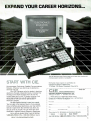
The CIE Microprocessor Trainer helps you to learn how circuits with
microprocessors function in computers.
START WITH CIE.
Microprocessor Technology. Satellite Communications.
Robotics. Wherever you want to go in electronics...
start first wth CIE.
Why CIE? Because we're the leader in teaching
electronics through independent study. Consider this.
We teach over 25,000 students from all over the
United Stales and in over 70 foreign countries. And
we've beer doing it for over 50 years, helping
thousands of men and women get started in
electronics careers.
We offer flexible training to meet your needs.
You can start at the beginner level or, if you already
know something about electronics, you may want to
start at a higher level. But wherever you start, you
can go as tar as you like. You can even earn your
Associate in Applied Science Degree in Electronics.
Let u get you started today. Just call toll -free
1-800 -321 -2155 (in Ohio, 1- 800 -362 -2105) or mail in
CIRCLE
7 ON
FREE INFORMATION CARD
the handy reply coupon or card below to:
Cleveland Institute of Electronics,
1776 East 17th Street, Cleveland, Ohio 44114.
CIE
AHO-104
World Headquarters
Cleveland Institute of Electronics, Inc.
1776 East 17th Street
Cleveland, Ohio 44114
Please send your independent study catalog.
For your convenience, CIE will try to have a representative
contact you
there is no obligation.
-
Print Name
Apt.
Address
Age
Zip
State
City
Area Code/Phone No
Check box for G.I. Bill bulletin on Educational Benefits
Active Duty
MAIL TODAY!
Veteran
Just call toll-free
1- 800 -321 -2155 (in
Ohio,
1- 800 -362 -2105)
11
Electronics Library'
(Continued from page 8)
This practical guide shows readers what
to look for in communications software and
hardware. It includes prices, special features, and the names and addresses of
manufacturers of each product. It also gives
all the necessary information for accessing
on -line information services such as bulletin board systems, information utilities including CompuServe and The Source. and
many electronic -mail services.
The Complete Communications Handbook
is available for S12.95 from W rdware Publishing. Inc., 1506 Capital Avenue. Plano.
TX 75074.
good "packeteer." Finally, the author looks
ahead to the future of packet radio, including digital audio and video. and the evolution of the amateur -satellite program.
a
Mastering Packet Radio: The Hands -on
Guide costs $12.95, and is available at
bookstores, computer stores, electronics
distributors, or from Howard W. Sams &
Company. 4300 West 62nd St., Indianapolis, IN 46268; Tel. 800 -428 -SAMS.
CIRCLE 95 ON FREE INFORMATION CARD
BOB MIDDLETON'S HANDBOOK OF
ELECTRONIC TIME -SAVERS AND
SHORTCUTS
by Robert
CIRCLE 81 ON FREE INFORMATION CARD
MASTERING PACKET RADIO:
The Hands -on Guide
by Dave Ingram, K4TWJ
Packet radio -the technique of breaking
down information into small pieces ( "packets") and transmitting them over amateur
radio
a rapidly expanding field. This
easy -to- understand guide to packeting is
intended to put amateur -radio enthusiasts
on the cutting edge of the digital- communications revolution.
The book examines packet -radio technology and capabilities. from simple concepts to more technical subjects. It offers
precise explanations of what packet is. how
it works. why it is used, and the hardware
involved. Readers will learn about the roles
of home computers and data- communications terminals, and how to set up their own
packet stations.
-is
Information is included on packet networks. bulletin boards. HF-linking concepts.
Oscar satellites, and electronic mail. There
is a survey of amateur equipment for packet
radio, and tips for newcomers and veteran
amateur -radio enthusiasts alike on being
12
G.
Middleton
Packed with dozens of little -known tricks
of the trade. new testing techniques, and
time -saving shortcuts, this 378 -page handbook will make it easier to troubleshoot television, radio, CB. tape- recorder. intercom.
audio. CCTV. telephone, and digitally controlled equipment.
The book explains how DC voltages can
be added or subtracted with a voltmeter,
how a digital -voltmeter temperature probe
can be especially useful in analyzing digital IC temperature "signatures." and how a DC
voltmeter can be converted into a high -
performance dynamic ohmmeter that
automatically measures the internal resistance of "live circuits. It describes how to
use a DC voltage monitor as a DC current
monitor, make a sensitive test for amplifier
distortion with a DC voltmeter, and measure DC voltages in very -high impedance
circuitry using a two-DVM method that
draws no current from the circuitry under
Professional Publishing. Englewood Cliffs,
NJ 07632.
CIRCLE 99 ON FREE INFORMATION CARD
UNDERSTANDING MAGNETISM:
Magnets, Electromagnets, and
Superconducting Magnets
by Robert Wood
While scientists try to decipher its mysteries. people are using magnetism every day,
unaware of the scope of its influence on
their lives. That invisible force of attraction
is one of the fundamental forces in the universe. This book examines magnetic phenomena, and the relationship between magnetism and electricity.
The history of magnetism-from the discovery of the loadstone, to scientific pioneers ranging from Hyppolyte Pixii through
Joseph Henry. Wilhelm Weber. James Clerk
Maxwell. and Nikola Tesla
covered. The
book defines magnetism and geomagnetism. It explains natural magnetic phenomena such as the Northern Lights and magnetic effects op the weather. It covers ferromagnetic, paramagnetic, and diamagnetic
materials, and how they are used.
-is
iaM] f1SM
11,167æl5,
i/
fl}X.11t0YA0675
SOPF7ll,lNiANG MAXIS
test.
There are instructions for building a simple voltage -controlled audio oscillator that
permits the use of a tape recorder as a
DC voltage monitor. automatic internal resistance ohmmeters, and modified -emitter followers with zero- insertion loss. The
book discusses controlled- timbre tests and
digital -logic troubleshooting ground rules.
with examples of oscilloscope applications.
It describes a simple arrangement for using a tape recorder as a digital data memory storage unit. and cites the causes
of circuit loading when a meter is applied
in a comparatively high- resistance circuit.
With step -by -step instructions and detailed illustrations, the handbook is easy
to use It presents quick tests and testing
tips, professional advice on how to get the
most from new electronic test equipment.
and new ways to use conventional test equipment. Many new servicing techniques were
specially developed for this book.
Bob Middleton's Handbook of Electronic
Time -Savers and Shortcuts is available for
$16.95 from Prentice Hall, Business and
The book also describes the ways magnetism is used in homes and industry. It
illustrates DC circuits and introduces basic
semiconductors, coils, and electromagnets:
basic AC circuits and transformers are covered as well. The book discusses how magnetism is used in everything from doorbells
to particle accelerators.
Some simple experiments will underscore
the principles learned from the text. Those
include a compass, an electromagnetic relay, a galvanometer, a transformer. and an
electric lock. The projects presented -an
electric motor, a steam engine, and an electromagnetic- repulsion coil -are fully illustrated and contain complete parts lists.
Understanding Magnetism: Magnets, Electromagnets and Superconducting Magnets
is available for $10.95 from Tab Books Inc.,
Blue Ridge Summit, PA 17294 -0850; Tel.
1- 800 -233 -1128.
CIRCLE 98 ON FREE INFORMATION CARD
CABLE -TV
HANDBOOK OF VIDEO CAMERA
SERVICING AND TROUBLESHOOTING
TECHNIQUES
by Frank Heverly
By the end of this book, readers will be
expert in the repair and alignment of today's single -tube video cameras, and in how
to build a profitable TV-camera service business. Complete operational data details the
inner workings of video cameras. The step by -step techniques needed to troubleshoot
and service a wide range of video cameras
are accompanied by over 400 charts, diagrams. illustrations and photographs.
The handbook shows how video cameras work; how to accurately pinpoint the
trouble when they malfunction; how to remove, re- install. align. and adjust the pickup tube; and how to deal with customers.
Beginning with a basic description of every
type of design of today's video cameras
and how they work, the book goes on to
describe, in full detail. the individual parts,
circuits, and components that comprise
video cameras. There are hundreds of shortcuts for troubleshooting, repair, and alignment. Also included are listings of sources
for test equipment, special tools, and additional reference material, as well as a glossary of terms and abbreviations.
BONANZA!
Handbook of Video Camera Servicing and
Troubleshooting Techniques is available for
$16.95 from Prentice -Hall, Inc., Business
and Professional Division, Englewood Cliffs,
UNIT
MORE
'CALL FOR AVAILABILITY
Quantity
NJ 07632.
10 OR
ITEM
Price
Output
Channel
Item
TOTAL
PRICE
Each
CIRCLE 99 ON FREE INFORMATION CARD
HIGHER MATH FOR BEGINNERS
by
Ya. B.
Zeldovich
and I.M. Yaglom
This introductory text book -written by a
Russian mathematician and physicist, and
published in the Soviet Union -presents
mathematics as an integral part of the natural sciences. It concentrates on concrete
mathematical solutions to scientific problems without getting mired in the formal
foundations and logical subtleties that confound many beginners in higher math. In
doing so, the authors intend to transform
mathematics from a dry. difficult subject to
one of clear and natural concepts.
While aimed at newcomers to higher
mathematics-advanced high -school, vocational. and college students-the book is
not simplistic. Along with traditional topics
including analytic geometry and differential
and integral calculus, it introduces the notions of power and trigonometric series, and
examines simple differential equations. It
contains hundreds of examples and calculations; some are examined from more than
one angle and many are accompanied by
SUBTOTAL
Shipping Add
$3.00 per unit
COD & Credit
Add 5%
Cards
TOTAL
California Penal Code #593 -D forbids us
from shipping any cable descrambhng unit
to anyone residing in the state of California
-
Prices subiect to change without notice
PLEASE PRINT
Name
Address
Cashier's Check
Acct
City
Phone Number
Zip
State
E.
Money Order
#
_
; :
COD
1
Visa
'.1Jstercard
Exp Date
Signature
FOR OUR RECORDS.
-
I. the undersigned.
DECLARATION OF AUTHORIZED USE
that all products purchased. now and in the future, will only
authorization from local officials or cable company officials in
state laws FEDERAL AND VARIOUS STATE LAWS PROVIDE
PENALTIES FOR UNAUTHORIZED USE.
Dated
do hereby declare under penalty of penury
be used on cable TV systems with proper
accordance with all applicable federal and
FOR SUBSTANTIAL CRIMINAL AND CIVIL
Signed
Pacific Cable Company, Inc.
7325'/2 RESEDA BLVD., DEPT. # H -1
(818) 716 -5914
RESEDA, CA 91335
No Collect Calls
(818) 716 -5140
IMPORTANT: WHEN CALLING FOR INFORMATION
Please have the make and model # of the e. ui ment used in our area. Thank You
13
Electronics Library
AutoCAD as more than just an electronic
drawing board -and increase their personal
satisfaction, job security, and productivity
in the process.
The AutoCAD Productivity Book helps
the history of the theories presented. A
discussion of the essence of higher mathematics and its possible applications in physics and engineering is followed by examples involving specific physical problems
within those disciplines.
The 560 page book contains an extens¡ve section on two mathematical trends
that expand and generalize the
differential and integral calculus -complex
numbers and functions of a complex variable, and generalized functions. Finally.
there is a discussion of scientific trends that
use higher mathematics. intended to arouse
the reader's curiosity and to encourage further study.
Beginning, intermediate. and advanced
users learn how to tailor AutoCAD to their
specific design needs. The tutorial section
aimed mainly at novices and intermediate
users -gives step -by -step directions on using macros and the powerful AutoLISP pro gram. creating and modifying screen and
tablet menus. and automating drawings.
This second edition contains two added chapters on how to customize AutoCAD Release 9's new pop -up menus. and on tips
and tricks that boost speed and drawing
power.
In addition. many sophisticated AutoLISP
routines have been included in the
"AutoCAD Productivity Library' section. The
70 carefully selected AutoLISP routines and
time -saving macros that are presented in
-
classicalWD
SecandEaaan
,
PrOCACaiVitY
--
op,IJR
CJ
Higher Math for Beginners is available for
$51.00 from Prentice -Hall, Inc., College Division, Englewood Cliffs, NJ 07632.
/
/
that section illustrate the features and power
of customization, giving users more insight
into AutoCAD's powerful programming language. Novices are strongly advised to read
the tutorial section thoroughly before delving too deeply into the "AutoCAD Productivity Library."
CIRCLE 99 ON FREE INFORMATION CARD
professionals tap the subtleties beneath
the surface of AutoCAD that can make
it a powerful new tool with more speed,
power, and performance. It also details
how to achieve company wide linkage. and
integration of AutoCAD with engineering,
sales, purchasing, manufacturing, and desktop publishing.
THE AUTOCAD PRODUCTIVITY BOOK
(Second Edition)
by A. Ted Schaefer
and James L. Brittain
"Productivity" is the key word here. Readers learn to "work smarter" by using
MILL ELECTROAICS
SEND FOR
ITT PUSH
BUTTON
FREE
CATALOG
PIEZO WARNING
DEVICE
ITT MDPL series. 3/4" X
1/2" gray rectangular key
cap. S.P. S.T. N.O. Push to
close.
Rated: 0.1 amp
switching,
ftp?
25 amp carry
current. P.C. mount.
CATI PB -8
65c each
10 for $6.00
0
CORR
I
Murata Erie PKB8 -4A0
High pitched audible alarm
Operates on
3- 20 Vdc @ 20 ma.
1- high x 7/8- dia.
P.C. board mount.
CATI PBZ -84 $1.75 each
XENON TUBE
WIDE BAND AMPLIFIER
(41 3 db.
Gain: 19db @ f -500 hz 5 volt
operation. Small package 4mm dia. x 2.5 mm thick.
CAT* UPC -1651
2 for 91.00
10 for 94.50
100 for $35.00
10 AMP SOLID STATE
long flashtube prepped
with 3 1/2- red and black
leads. Ideal for electronic
flash or strobe projects.
CATI FLT -3 2 for $1 00
1-
RELAY
50 for $300 00 100 for $500
MOSFET
MAIL ORDERS TO:
ALL ELECTRONICS
P.O. BOX 567
VAN NUYS, CA 91408
TWX5101010163(ALL
ELECTRONIC)
OUTSIDE THE U.S.A.
SEND $1.50 POSTAGE
FOR A CATALOG!!
14
00
CIRCLE 80 ON FREE INFORMATION CARD
Great for the Experimenter!
ï.
f',
RS-232
BREAKOUT BOX
5wItCEable Lines
LED Indicators
& Jumpers
Patch Terminals
Compact Size
Il
Pioneer Laser Disc Player
1.2 rrrW Helwm -Neon
Laser
Laser Power Supply
$29,.9 5'
2 Front Surface Mirrors
Two 1/2 Voice Coil Actuated
Oscillating Mirrors
One Beam Sputter
Two Optical Lenses
One Optical Detector
Mini Gear Reduction Motor
All Controlling Electronics
DEL TEC
AC LINE
CONDITIONER
Assorted Switches. Fan, Solenoid
"As-ls"
'
IRF -511 TO -220 case
CATI IRF 511
$1.00 each
10 for $9.00
LARGE QUANTITY
AVAILABLE
ORDER TOLL FREE
800 -826 -5432
INFO: (818)904 -0524
FAX: (818)781 -2653 DISCSVER
MINIMUM ORDER $10.00
QUANTITIES LIMITED
CALIF. ADD SALES TAX
USA: $3.00 SHIPPING
FOREIGN ORDERS
INCLUDE SUFFICIENT
SHIPPING. NO C
0.D
CIRCLE 5 ON FREE INFORMATION CARD
I®
Eliminates
Ideal
400 WATT
PC or Any Equipment
C Line Noise
Regulates to a
and
Constant 120
VAC
Transformer
R 1acaWvee Case
se with Power
Outlets. and
SwitChh
Breaker
$99.00
t
300w 2500W
5pppsy,SO
We stockTHOUSANDS of parts!
IC's. TRANSISTORS. MORE...
AW
Mitsumi UVE
UHF
1
P
DISPLAY
VHF
PAGING
VARACTOR
TUNER
..'
RECEIVERSuperhe'4
Dual Conversan
kiHiplug
C'ysW
LEO Dis1Aer
Char Alphe-Nemeoc
Twenry
ANSI Caer Sel )
(ASUI Enceded.
each
sesee
12"
. 31/2-.2..112"
31 /2- x 2" x
Pinout on Case
TWO
FOR
aula0 0
ie
CALL!
N- CHANNEL
ELECTROL IS2161
CONTROL:5.5 - 10 Vdc
t will operate 3- 32Vdc)
LOAD: 10 Amp @ 240 Vac
2 1/4- X 1 3/4- X 7/8"
CATI SSRLY -10B $9.50 each
10 for $85.00
25 for $175.00
NC 27515.
THESE UNITS ARE
OEM MODELS AND
REQUIRE A COMPUTER
CONTROLLER
(NOTAVAILAeLE FROM
HALTED) THEY
CANNOT 8E MANUALLY
CONTROLLED,
N EGNUPC1651G
1200 Mhz
The AutoCAD Productivity Book: Second
Edition is available for $39.95 from Ventana Press, P.O. Box 2468, Chapel Hill,
RCACDPti102
Peizoelecin<Beeper
Ain
viUsed.
Used. umaalad,
"Aa
$17.95
.7
i1
is
-lí
95
$1
.P
Cali the
Halted Specialties
Electronic Forum
BBS'
408 -732.2814
510 MINIMUM ORDER
QUANTITIES LIMITED
CA RES. ADD SALES TAX
HSC of Santa Clara
3500 Ryder Street
Santa Clara, CA 95051
Call
Rr` Z,
No w! R
°
800 -4- HALTED
408- 732 -1573
CIRCLE 8 ON FREE INFORMATION CARD
Official 1934
USING THE MODELS 50 & 60
by Herbert Schildt
This guide to IBM's new machines in the
Personal System/2 series contains all the
information necessary to handle the Models 50 and 60 effectively.
The book's first section, though intended
primarily for beginners, contains some interesting facts about the history of those
machines. It goes on to discuss their basic components, define several fundamental computer terms, and to explain how to
start the computer and use the Reference
Diskette.
The projects, which include all the information needed to construct the basic building blocks of any personal robot, are geared
to novice and intermediate robotics enthusiasts. Included are various modules for the
body and frame, power and locomotion, appendages, "facial" features, navigation, and
electronic control. The reader can combine
various modules into different configurations
to create rolling, walking, or talking robots
robots that can serve drinks, vacuum the
floor, protect the family against fire or theft,
or teach the children.
The book suggests alternate approaches
and sources of electronic and mechanical
components. Most of the circuits use discount- priced, surplus ICs that are easy on
the builder's budget. Along with illustrations,
schematics, diagrams, and parts lists for
each module, the book provides a listing
of necessary tools and equipment, a guide
for matching up TTLs and ICs, and drill-bit
and bolt chart, and computer programs that
are useful in robotics.
233 -1128.
Using the Models 50 & 60 costs $21.95.
It is available from Osborne McGraw -Hill,
2600 Tenth Street, Berkeley, CA 94710.
CIRCLE 96 ON FREE INFORMATION CARD
THE ROBOT BUILDER'S BONANZA:
99 INEXPENSIVE ROBOTICS PROJECTS
by Gordon McComb
This educational, yet fun, book takes a modular "cookbook" approach to robot building.
It offers a unique collection of fully tested
project modules that can be mixed and
matched in countless combinations. The
reader's imagination is the other ingredient
required for the creation of highly intelligent, one -of -a -kind, working robots.
RADIO MANUAL
-
The Robot Builder's Bonanza: 99 Inexpensive Robotics Projects costs $14.95.
It is available from Tab Books Inc., Blue
Ridge Summit, PA 17294 -0850; Tel. 1 -800-
Users of the Models 50 and 60 have a
choice of operating systems, and this book
contains extensive sections on both the current standard, DOS, and the powerful new
OS /2. There is a brief discussion of their
similarities and differences, and the advantages and disadvantages of each. The DOS
section has an introduction to its basic features, and proceeds to commands, system
configuration, and advanced DOS features.
For the OS /2 user, the book explores multitasking, the program selector, and other
OS/2 features.
Hardware specifics are also covered in
detail, with the emphasis on how things
work. Memory, 80286 specifics, interrupts,
disk drives, keyboard, video, and printers
are described.
SHORT WAVE
CIRCLE 98 ON FREE INFORMATION CARD
62 HOME REMOTE CONTROL AND
AUTOMATION PROJECTS
by Delton
T.
Horn
Even readers with no previous electronics
experience will find useful projects that they
can build and put to use at home. The devices in this book were designed to make
life safer, more convenient, and more fun.
A wide array of door and window controllers, stereo and TV projects, timers, electronic- switching units, wireless controllers,
telephone -related projects, and a computer
controller with programming information are
presented. Specific projects include an automatic guest -greeter, sensors to keep heat
and air-conditioning at ideal levels, a remotecontrolled "commercial killer" for the TV,
and voice -activated transmitters and relays.
Before getting into project- building, there
is a simple, but thorough introduction to
how remote -control and automation systems actually work. Advice on safety precautions, finding parts, substitution of components, and techniques for customization
is also presented in the first few chapters.
Then, for each device, the author supplies
complete instructions, wiring diagrams, and
illustrations.
62 Home Remote Control and Automation
Projects is available for $12.95 from Tab
Books Inc., Blue Ridge Summit, PA 172940850; Tel. 1- 800 -233 -1128.
CIRCLE 98 ON FREE INFORMATION CARD
Build
simple. high
performance old time shortwave radi
All of the secrets are
here: the circuit diagrams.
parts layout. coil specifications. construction details. operation hints. and
much more!
This is a compilation of shortwave
construction articles from "Short Wave
Craft" magazines published in the 20's &
30's. It's wall -to -wall "how-to."
Included are circuit diagrams. photographs. and design secrets of all shortwave receivers being manufactured in
1934 including some of the most famous: SW-3, the SW-5 "Thrill Box ", the
the Hammurland
and many more.
Also included is a new chapter showing how you can use transistors to replace hard -to -find vacuum tubes. You'll
even see the circuit that was lashed
together on a table top one night using
Junk box parts. a hair curler and alligator clips. Attached to an antenna strung across the basement ceiling and a 9 volt battery. signals started popping
deForest
KR -1,
"Comet Pro
in like crazy. In a couple of
minutes an urgent message
from a ship's captain off Seattle over 1500 miles away
was heard asking for a navigator to help him through shallow water!
These small regenerative receivers
are extremely simple, but do they ever
perform! This is a must book for the
experimenter, the survivalist who is
concerned about basic communication,
shortwave listeners, ham radio operators who collect old receivers. and just
about anyone interested in old -time
radio.
Great book! Fun to read! One of the
best old -time radio books to turn up in
years. Heavily illustrated! Order a cop%'
today! 8 1 /2 x 11 paperback 260 pages
only $15.70 postpaid!
rLindsay Publications,
Box 12 -WF3, Bradley IL 60915
a copy of Short Wave Radio
D Send
Manual Enclosed is $15.70.
Chk. MC. Visa. Send a free catalog of other books.
Name
z
Address
Ly
St
Zip
J
I
15
ing of sensors. There is an instant panic
alarm for emergencies.
New Products
uhiu
oll 111111,rr,dWö rnrerrd in dri xrrinn /rr un h< nramdar nue r.
Irleax circle du item' I code 11unrher 11 rlrr Fr-ee
Information ('ard
Ta
TALKING SECURITY SYSTEM
The Dicon 9000 wireless security system
verbally instructs the user on how to program and test the system. It also vocally
reports which sensor has triggered an
alarm. verifies that transmitters are within
receiving range. and reports when transmitter or console- backup batteries require
replacement.
Easily installed by consumers. the system fully integrates security. fire. medical,
and other emergency monitoring. using a
variety of sensing devices with miniature
transmitters. The central console is about
the size of a telephone- answering machine.
It has a built -in automatic telephone dialer
that is capable of calling eight local or long distance numbers and relaying an emergency message in the user's own voice.
V
If an emergency occurs. the console determines whether a security, fire, or medical alarm has been triggered. It will automatically place an emergency call to the
appropriate pre -programmed number or numbers. An electronic voice announces to the
answering party: Medical Emergency' or
Fire Emergency as appropriate. then delivers the user's own message. Each message is repeated three times before the
console hangs up and dials the next emergency number.
Codes. rather than conventional keys.
are used to arm and disarm the software based system. (Authorized visitors can be
provided with a temporary "visitor code.')
Different monitoring and alarm modes are
used when the occupants are at home or
away. Up to four separate security zones
can be created, allowing selective monitor-
16
The Dicon 9000's digital signal- coding
system and sensors are made with surface mount components resulting in compact
size. and improved quality and reliability.
It is designed so that even close neighbors
can use it without interfering with each
other's systems.
The basic Dicon 9000 package consists
of the console, two magnetic window door
switches with transmitters, a speaker siren
with a 50 -foot cord. an AC -power adapter.
a modular -telephone cord. an extended range antenna. and window decals. Optional accessories -full- function remote controls. infrared motion detectors, personal or medical- emergency pendants. smoke
alarms, additional window and door
switches and indoor sirens, and a weatherproof outdoor siren-are available. Temperature sensors and propane natural gas
detectors will be available in late 1988.
The Dicon 9000 package. including all
hardware and installation materials and an
operator's manual with diagrams of suggested sensor placement. costs $494.00.
For additional information. contact Dicon
Systems Inc.. 631 Executive Drive, Willowbrook. IL 60521: 1- 800 -387 -2868.
CIRCLE 69 ON FREE INFORMATION CARD
MOVING -COIL HEADPHONES
Signet's EP400 is a moving -coil design stereo headphone that delivers peak -free response and accurate reproduction at both
ends of the spectrum. A high -flux Samarium cobalt magnet and oxygen -free silver
copper wire are used for the voice -coil winding. Oxygen -free copper is used in the 10foot audio cord to provide maximum conductivity and minimal signal loss. and to
yield extended dynamics and distortionf ree sound. Its frequency range is from 20
Hz to 22,000 Hz.
The headband and earpads are comfortable even during extended periods of
use. The adjustable double- headband system combines strength and rigidity with even
weight distribution. Mesh-covered foam ear pads- mounted with a dual -swivel system
allow adjustments for individual head shape.
and provide good performance with the greatest degree of comfort. Strain-relief pieces
at the earpads and plug assure durability
and trouble -free operation.
The EP400 headphones cost $100.00.
For further information. contact Signet. 4701
Hudson Drive. Stow. OH 44224.
-
CIRCLE 70 ON FREE INFORMATION CARD
WORDPREFECT LEARNING TOOL
PC Template's PerfectPal version 5.0 is
an updated version of their productivity tool.
and is designed to make WordPerfect easy
to learn and use. When used with WordPerfect versions 4.1. 4.2. or 5.0, the system
of more than 375 simple -to -call. pre coded macros allows users to greatly reduce the number of key strokes needed
for even the most complex -and seldom
mastered-WordPerfect functions. The package also includes 50 pre- formatted page style setups and a guide to WordPerfect's
keystrokes.
The system offers mnemonic key strokes
that are named for every WordPerfect Command ("P" for print. "BOX" for box line drawings, etc.), allowing even novices to advance quickly through word -processing commands without constantly referring to the
manual. More than half of the macros feature pop -up tips. prompts. and instructions.
PerfectPal version 5.0 commands include
moving copying text in two key strokes, one stroke tab sets, pre -set sorts and fonts. easy
merge. and simplified math and desk -top
publishing. All those, and more. are accomplished in one or two keystrokes instead
of struggling through layers of menus. Other
complex tasks -including columns. cross references, and lists -are also pre- coded.
Pop -up instructions help the user master
setting up tables of contents, indexes. book
chapters. and graphic images.
PerfectPal can automatically map the keyboard with special science or math signs,
or foreign -language characters. With one
macro, it can change the keyboard to Span-
ish, for example, and back to English again
with another macro. Specific routines for
the legal profession are also included.
The PerfectPal package -including two
system disks, two 3- by 18 -inch plastic coated templates displaying commands.
and a user's manual -costs $79.00. For
more information, contact PC Template.
P.O. Box 9273, Glendale. CA 91206: Tel.
1- 800 -451 -6086.
CIRCLE
71 ON FREE
The Curtis 5' a-inch and 3' 2 -inch disk files
have adjustable dividers with color -coded
labels, carrying handles, and anti -skid feet
to anchor them securely to any desk top.
They hold 50 and 40 disks, respectively.
Snap -lock models and units featuring an
all -steel security lock with two keys are available in each size. Every disk file has an
outside shelf designed to hold two or three
working diskettes.
The Curtis 3' 2- and 5' 4 -inch disk files
cost $12.95 each with security lock, and
and scratch and crack resistance. The files
offer maximum protection for delicate floppy
disks.
INFORMATION CARD
DESOLDERING GUN
Xuron's WickGun desoldering system removes solder from PC boards and other
electronic devices 3 to 5 times faster than
the conventional use of braid. The tool makes
the dispensing, positioning, and cutting of
desoldering braid a one -handed operation.
The WickGun accurately dispenses the
desired length of desoldering braid. When
heat is added with a soldering iron the
melted solder is drawn up into the exposed
braid. The solder- impregnated braid is easily cut off by squeezing the trigger. The
desoldered area is left clean and free of
contaminants such as finger oils. That improves future solderability. The WickGun
also acts as a heat shield to prevent burned
fingers.
*
CABLE TV
SPECIALS
CONVERTERS
JRX -3 DIC
-36
Channel Corded Remote. 5129.95
RCA 58 -3 58 channel set top with
SB -3
-
599.95
Jerrold Descrambler
'The Real Thing'
5109.95
589.95
SB -3- Taiwan Copy
DRZ- 3D1C
-68
Channel Wireless
5199.95
with Descrambler
Cable Add -On
ZENITH:
Z -TAC
VIEW STAR:
MXC 2001
-65
Channel Wireless
-
5169.95
with Parental Lockout
MXC 2001 A -B
-Same
A -B
MXC 2501
-65
589.95
as above with
Switch
5109.95
Channel Wireless
5119.95
with Volume
Universal V7472 -72 Channel Wireless Remote
MTS Stereo Converter -Full
Feature Descrambler
Compatible
The unit is made of static -dissipative materials. in keeping with current ESD- control
practices. Easy -loading replacement -braid
cartridges are available in 15 -foot lengths
in sizes
through 4. The cutting blades
are also replaceable.
The WickGun has a suggested list price
of $39.95. The replacement -braid cartridges
cost $4.95 each for sizes through 3, and
$5.25 for size 4. For more information. contact Xuron Corporation, Saco Industrial
Park, 60 Industrial Park Road. Saco. ME
04072.
CIRCLE 72 ON FREE INFORMATION CARD
589.95
ECONO -3V Mini -Code
OAK:
ECONO -3V
1
1
5129.95
MISCELLANEOUS
S89.95
Mini -Code Vari -Sync
ECONO-3V Mini -Code Vari -Sync Plus
5119.95
Auto On -Ott
OAK:
Sine -wave Anti -Jammer Kit
JERROLD:
400 & 450 Handheld Transmitters
539.95
529.95
HAMLIN:
MLD -1200 Channels
599.95
NEW ITEMS:
Scientific Atlanta SA -3
2
or
3
5129.95
GENERAL
INSTRUMENTS: VCU Amplified Video Switch
Signal Amplifier
FLOPPY -DISK FILES
Curtis' line of floppy -disk files are made
-a
new plastic
of CTE acrylic copolymer
featuring high levels of durability, resilience.
559.95
UNITED ELECTRONIC SUPPLY
P.O.BOX 1206H
ELGIN, ILLINOIS 60121
z
>
312 -697 -0600
CIRCLE 15 ON FREE INFORMATION CARD
17
New Products
PORTABLE OSCILLOSCOPE
$9.95 each with snap lock. For more information, contact Curtis Manufacturing Company Inc.. 30 Fitzgerald Drive. Jaffrey, NH
03452.
CIRCLE 73 ON FREE INFORMATION CARD
TWO-WAY PORTABLE RADIOS
The Regency Plus HH Series of die -cast
two -way portable radios are durable and
dependable, yet lightweight. With die -cast
metal mainframes, the portables are rugged under working conditions.
The HH Series is available in three
bands. In UHF, the HH 464 D2 and HH
464 D4 have four watts of power and two or four -channel capability. In VHF High
Band, the HH 154 and the HH 156 feature
4 or 6 watts of power. switchable to watt.
and up to six -channel capability. The series is rounded out by the HH 505. with 5
watts of power and four channels in Low
Band.
Tektronix' Model 2247A portable oscilloscope, aimed at the digital- design and field service markets, features a counter timer,
automatic rise fall -time and propagation delay measurements, and other extended
measurement capabilities. The 100 -MHz,
4- channel scope provides auto setup, onscreen cursors, and up to 20 pre -programmed measurements.
The unit features 11 automatic voltage
and time measurements. In addition to rise'
fall -time and propagation -delay measurements, the 2246A's built-in counter,timer provides delta time, gated- counter measurements, and frequency-ratio measurements.
The oscilloscope offers several gated measurements that allow the user to choose portions of the waveform for closer analysis.
Users can also make measurements on
the delayed sweep; by simply positioning
the scope's cursors on the expanded waveform. the numeric value appears on screen.
Operator prompts and on- screen error
messages guide users through the proper
setup and measurement procedures.
There are prompts for proper AC or DC
settings, and for proper control settings,
(Continued on page 22)
1
NOTHING
COMES
EASY
By Jack Schmidt
When
I said that
we are
dealing Kith
'limited memory'. I Kas not talking about
the computer, I Kas talking about sou!"
"M'Lord, l can't pick up not
a thing on
my stereo headphones in here."
LJL
The crystal -controlled radios are adaptable to radio common carrier and to systems with all standard -EIA subaudible
(CTCSS) tones, two-tone sequential. and
various other signalling formats. All models carry a 2 -year limited warranty.
The suggested retail prices for models
HH 464 D2 and HH 464 D4, are $569.00
and $615.00. respectively. Models HH 154
and HH 156 cost $459.00 and $550.00.
respectively. Model HH 505 sells for $549.00. For further information, contact
Regency Land Mobile. Inc.. 7707 Records
St.. Indianapolis. IN 46226.
CIRCLE 74 ON FREE INFORMATION CARD
"Oh Mr. Communicator. I don't think
you're putting out enough power!"
"Melvin, is it true you bought an e.cercise
bike Jar your robot''"
"Byron. the computer company sent the
retrofit instructions ou a floppy disk."
NOW' Training includes XT-compatible computer
plus NRI's remarkable Robotic Discovery Kits!
Get training for industry's
hottest new jobs as you
build and program complete
robotic control systems
Now you can get the skills in demand for the new jobs in industry
today. With NRI's new at -home training in Robotics Technology, you
actually build a fully IBM XT- compatible computer, then use it to
program and control working robotic systems ... each one
engineered to recreate the exact operations performed by the robotic
equipment found in today's industrial workplace.
Its no secret. Industry is being transformed
by technology-with everything from
precision electronic instruments to giant
locomotives now being produced with the
help of advanced robotic systems. And with
automation have come jobs ... thousands of
jobs building, programming, and servicing
the robotic systems in use today.
Now, unlike any other school, NRI offers
you training that prepares you to take
advantage of these new opportunities ...
training that gives you the practical know how and the hands-on skills to advance on
Robotics comes to life as you
see real -world industrial control
principles in action
Ybur NRI Robotic Discovery Kits come
complete with everything you need to
create working, moving robotic systems.
You get structural members, motors, gear
drives, sensors, scanners, potentiometers,
plus a special Robotics Interface that links
the robots you build to your computer.
Together, your computer and the robotic
devices you construct become fully integrated
know
ledge of
electronic circuits and components as you
experiment with your NRI Discovery Lab®
and professional digital multimeter.
Rapidly, theory becomes understanding as
you move on to digital logic, computer fundamentals, right up to writing practical programs to control specific robotic operations
using NRI's Robotic Programming Language
software included in your course.
Your success is assured by your personal NRI
instructor, whose expertise and personal
guidance are always available to you whenever
you need a helping hand along the way.
Get training you can build a career
on -send for your FREE catalog today!
how NW's breakthrough training can put you at the heart of the robotics
revolution. Send today for NRI's big, 100 -page,
full-color catalog that gives you all the details
about NRI's exciting new training in Robotics
Technology, plus training in computer electronics, TV /video /audio servicing, electronic
music technology, security electronics, and
other growing high-tech career fields.
If the coupon is missing, write to: NRI School
of Electronics, McGraw -Hill Continuing Education Center, 3939 Wisconsin Avenue,
Washington, DC 20016.
See for yourself
fitly
Two tasks
This
pee
famed by robots we
nrs«abng and sorting, be it sating eggs or eliminating scrap
hum a production line You Wad this sorting system, thin
program It to accept short and long blocks, measure Mete
blocks, and more them to to comet storage bins.
the job or start a new career as a robotics and
industrial control technician.
The powerful XT-compatible computer
you build becomes central control for the
robotic systems you construct
As an integral part of your NRI hands-on
training, you build a fully IBM XT-compatible computer from the keyboard up.
You assemble the power supply, install the
51/4" floppy disk drive, and attach the high resolution monitor. Most important of all, by
performing meaningful tests and demonstrations at each stage of assembly, you
come to a full understanding and appreciation of the microprocessor technology that
makes today's robotics applications possible.
But that's just the beginning.
You go on to use your computer to program and control a diverse array of robotic
systems you create with NRI's remarkable
Robotic Discovery Kits.
'teachable"
robotic arm
is the
most complex robot
model you construct. Once you
mentallyy put the robot through a segrnnce of operatans. it wnl
-nMMmbe/' theta steps are perlpm them whenever ar ed
automation systems, programmed by you to
do the types of operations and tasks performed in today's industrial environments.
Tasks such as plotting polar coordinates to
create graphic displays of numeric data ...
sorting different size objects and routing
these objects to separate containers ... even
performing a preprogrammed sequence of
operations again and again just as robots
now do on manufacturing lines.
Nothing is left out, nothing is left to chance.
You get everything you need-the skills, the confidence, and the equipment -to feel completely
at home with today's robotics technology.
Step by step, you get the training you
need to move into robotics fast
You need no previous experience to succeed
with NRI training, because NRI takes you from
electronics basics all the way up to the state of
the art in robotics technology. You train from
the ground up ... First gaining a working
McGraw -Hill Continuing Education Center
3939 Wisconsin Avenue
For career courses
Washington, ne 20016
approved under 01 Bill
check for details
Check one catalog only
Robotics T'rhnokagy
Computers .uni
processors
Micripria
Security Flecvaixs
F7rctromic Music
TVAIdeoo Audio Servicing
'rmtmunicationu Electronics
Telephone Servicing
g
Data Communications
Basic Electronics
s
Digital Electronics
Servicing
Name
Address
City
State
Zip
Accredited by the National Home Study Council
I
fi-019
21
,
r
New Products
tery" light indicates when to change the
(Continued from page 18)
CHEMICAL
SOLUTIONS
FREE CHEMTRONICS CATALOG!
Comprehensive new source for over
200 products used in electronic manufacturing and field service. Precision
cleaning agents. flux removers, bulk
solvents. circuit refrigerants. precision
dusters, non -residual wipers. foam
swabs. premoistened pads swabs.
antistatic compounds, conformal coatings, lubricants, adhesives, desoldering braids, rosin core solder and solder
masking agents. Complete with technical specifications and application
guide.
&Chemtronics Inc.
681 Old
L
wints, i',,.,
Hauppauge.
N Y
11788
516-5823322
CIRCLE 20 ON FREE INFORMATION CARD
9 -volt battery.
such as triggering and sensitivity levels. The
scope features smooth, menu -driven operation; automatic. one -button front -panel
setups; and the ability to store and recall
as many as 20 setups. SmartCursors track
changes in the voltage. trigger, and ground
level of the displayed waveform, shortening the setup time for single -shot triggering
and peak -voltage, DC. and other measurements.
The 2247A portable oscilloscope, with
a 3 -year warranty on labor and parts (including CRT), has a suggested list price
of $2795.00. For further information, write
on company letterhead to Tektronix, Portable Test Instruments Division, P.O. Box
1700. Beaverton, OR 97077; or call -800426 -2200.
The WSC -110 Wrist Strap Checker costs
$85.00. For more information, contact
Wescorp, 144 South Whisman Rd., Mountain View, CA 94041; Tel. 800 -537-7828
(415- 969 -7717 in California).
CIRCLE 76 ON FREE INFORMATION CARD
DIAMOND- SCRIBING TOOL
Minitool's #PV -078 Pin Vise Handle has
tiny -0.5mm (.020 -inch), and 0.25mm (.010 inch) -tip sizes. It can be used for repairing thin film circuits, micro circuits. and fine line PC boards and integrated circuits. Other
applications include scribing under a microscope, and precision scribing.
1
CIRCLE 75 ON FREE INFORMATION CARD
WRIST -STRAP CHECKER
Wrist straps often fail to provide a constant
path from the wearer to ground. Such failures can be caused by a loose strap. oil
or creams on the skin, open resistors in
the molded cord, poor contact of snaps from
the band to the cord, or poor grounding
of the strap to an earth ground.
Wescorp's WSC -110 Wrist Strap
Checker is designed to assure the wrist strap wearer of continuity, from the banana
plug at one end to the wearer's hand at
the other. To check for continuity, the wearer
The high-precision pin -vise handle includes a collet adapter for use with those
diamond -scribe tips. It also comes with a
standard collet for use with knives and special tools from 1.5mm to 2.3mm in size.
The non -roll handle offers a precision drawbar, ridged finger grip. and low- friction
bronze bushing.
The #PV -078 Pin Vise Handle costs
$14.95. The .5mm tip. #PV- 078 -U, costs
$9.95. and the .25mm tip. #PV- 078 -U2,
costs $14.45. For more information, contact Minitool, Inc., 1334 F Dell Avenue,
Campbell. CA 95008.
CIRCLE 77 ON FREE INFORMATION CARD
TWO -PORT RS -422 INTERFACE
simply plugs it in at the banana jack, or
clips it on the post or snap provided with
the unit, and touches the contact bar on
the face of the instrument. A series of indicators include a high- reading light (over 10
megohms series resistance). a low -reading light (under 1.0 megohms resistance)
and a "pass" light plus audible signal to
indicate satisfactory operation. A low bat22
CIRCLE 6 ON FREE INFORMATION CARD
MetraByte's DUAL -422 two-channel RS422 interface board provides high speed
communications capability for IBM PC XT
AT and compatible computers. It allows data
transfers at speeds of up to 57.6 Kilobaud
over distances as large as 4000 feet. The
baud rate can be selected over a wide range
of values between 120 baud and 57.6 Kilo baud. Through simple BASIC programming,
the 9600 -baud limitation of most DOS and
BASIC communication routines can be overcome. Applications include interfacing the
microcomputer to printers, plotters. modems. networks, and instrumentation; and
communicating with signal- conditioning and
control systems.
The board has two independent RS-
422A communications ports, each with its
own base address- and interrupt -selection
codes. Either channel can be set as COM
1:, COM 2:. or any other desired base address interrupt level combination.
unit. which produces 10- watts -per -channel
into four ohms. also has a loudness control, pre -amp outputs. auto- reverse. and a
power- antenna lead. The SJS 7000 features "Flex Fader" that allows the fader to
be used even with outboard amplifiers.
Model SJS 8000. a 3 -hole universal mount unit. allows the radio to be heard
while a tape is rewinding or advancing. It
has tape search. "Ultra Bias- tape head.
"Flex Fader ". and a CD input. The unit produces 30- watts -per -channel of output into
four ohms. It also features scan tuning,
Dolby B noise -reduction circuitry. autoreverse. 24 station presets, and separate
bass and treble controls.
The top -of- the -line Model SJS 9000 is
designed for theft prevention. The user can
easily pull it out of the dashboard when
leaving the car. In addition, it offers all the
features of the SJS 8000. including 30- wattsper- channel of output into four ohms.
Models SJS 7000, SJS 8000. and SJS
9000 carry suggested retail prices of
$239.95. $269.95. and $320.95. respectively. For more information, contact International Jensen, 4136 North United Parkway. Schiller Park, IL 60176; Tel. 800 -323-
$260.00; the 9 -pin D" connector costs
$12.00, and RS -422 cable costs $25.00.
For further information, contact MetraByte
Corp.. 440 Myles Standish Blvd.. Taunton.
MA 02780.
CIRCLE 78 ON FREE INFORMATION CARD
CAR STEREOS
The DUAL -422's design is based around
the INS 16450 UART. giving it compatibility with both the INTEL 8250 UART and
IBM asynchronous card. Communications
parameters-such as 5.6. 7. or 8 data bits
and even -, odd -, or no- parity check modes
are software selectable by the user.
The board plugs directly into any unused
half -or full -size IBM PC XT AT expansion board slot. It is connected to external serial
busses through the board's two 9 -pin "D"
Jensen's three top -of- the -line autosound receivers feature sleek styling and upgraded
electronics.
Model SJS 7000. a full- featured mini chassis, has a backlit LCD display. 24 station
presets (12 AM;12 FM). and separate bass
and treble controls. For improved performance, it offers "Ultra Bias" tape head. "Instaloc" automatic program -control tuner.
and Dolby B noise -reduction circuitry. The
-
0707.
connectors.
The DUAL -422 Interface Board costs
CIRCLE 79 ON FREE INFORMATION CARD
DON'T LET
THIS HAPPEN
TO YOU!
I
Was A Wreck Until
I
Started Ordering My Parts
From The MCM Electronics
Catalog!
Since I made the switch to MCM Electronics, I can choose from
their huge assortment of over 11,000 products. If I have a question
about a particular item, can call and get the answer. If need
when need it! And the best part of
something fast, can get it
all is that everything I've ordered has performed as promised...
with no exceptions! I couldn't ask for anything more. And neither
TODAY!
could you! Make your switch to MCM
I
I
-
I
I
-
For your FREE copy of our all -new MCM
Electronics Catalog...
CALL TOLL -FREE
1- 800 -543 -4330
In Ohio, call 1- 800 -762-4315
In Alaska or Hawaii, call 1- 800 -858-1849
MCM ELECTRONICS
F CONGRESS PARK DR
CEN1 FRVII l F. OH 45459-40 12
A PREMIER Company
85B
SOURCE NO. HO -22
CIRCLE
11
ON FREE INFORMATION CARD
table that
Think
Tank
if
he'd get a burglar alarm
for his store, he could cut down on the
cost of his insurance premiums. Being
an electronics hobbyist, offered to
build him one. got a "That's a good
boy," look and the maffer was disI
I
missed.
I
worked up the enclosed circuit
(See Fig. 2) but dad was too busy to go
By Byron G. Wels
SCR PROJECTS
over it with me, so built it and installed
it in the store. He didn't have time for it
until he heard the bell go off, and suddenly he became interested.
figured that any crook would come
through the front door, one way or another, so put a switch mat under the
carpeting just inside the front door The
alarm circuit is connected to the SCR
anode and gate. Pressure on the mat
closes the contacts of the mat switch,
which applies current to the SCR gate,
causing it to conduct.
With the SCR conducting, a path to
ground is provided through BZ1 (a 6- to
12 -volt bell) and SCR1, causing BZ1 to
sound. The bell continues to sound,
even if the crook steps off the mat. To
turn the alarm off, you have to manually throw switch S1 to break the circuit. During the day, when customers
are going in and out, simply open the
switch and the alarm is disabled until
you throw the switch on again, to arm
the circuit.
I
I
Back in the early days, if you wanted to control a motor's speed, you
had a "brute force" rheostat with a
control wheel the size of a small car's
steering wheel on it. It usually took an
ape of a guy with two hands on the
wheel to slow down or speed up the
motor. Then solid state came along,
and voltages were dropped to the
point where you could actually touch
a contact and not draw an arc. And
the steering -wheel sized rheostat gave
way to a small knob that you could
operate with two fingers.
To a large extent, that was due to a
device called a silicon controlled rectifier. Essentially, it was a diode with an
added terminal that was used as (and
was called) a gate. Thanks to the SCR,
small voltages could control large
voltages, and not through relays that
had only two steady states. You could
now control a full range of voltages. As
time (and science) progressed, new
applications were discovered for that
versatile device, and we're glad to offer a range of them here.
SCR Tester. This handy little unit will
give you a visual indication, is a one evening project, and is easy to throw
together. Once you've got it, you can
check the operation of all those possible duds in your junkbox, and maybe
throw some of them into the scrap
heap.
Figure shows a 3 -amp, 50 -volt SCR
and a test circuit. A fixed resistor can
be used for R1. Points G (gate) and K
(cathode) are temporary connections
so that they can easily be opened. If R1
is a fixed resistor of a few -hundred
ohms, when K is closed, the lamp
doesn't light. When G is also closed,
the lamp lights to its full intensity. The
lamp remains lit even if G is opened
again. But when K is opened, even momentarily, the lamp does not light
again when K is closed. It does so
when G is closed. That illustrates the
1
24
"on" and "off" operation of the SCR.
If R1 is of a higher value, about
50,000 ohms, you can place a meter
at G to show the gate current (IG). A
small gate current flows that rises as
you reduce the value of R1. At some
given value of IG, the SCR begins to
conduct and the lamp lights. Using a
standard 3 -amp, 50 -volt SCR, conduction begins at an
of perhaps
I
about 0.5 mA.
+12v
n
12V 6W
R1
27012 -50K
(SEE TEXT)
A
SCR
UNDER
TEST
G
I. The SCR Tester -which provides a
visual indication -is simply a to/ta,t'e
source, an indicator lamp, and a resistor
through which ,Gate current is supplied.
F,,>'.
I
CONTACT
MAT
+12V
can make an additional test by
supplying the current from an adjustable voltage source, enabling you to
determine the SCR's turn -off point.
Close K then temporarily close G. Reduce the anode -to- cathode supply to
about 2.0 volts, return to 12 volts, and
note that the lamp remains lit. Further
reduce the supply to about 1.0 volt and
repeat the check. You'll find a point,
where if the supply is reduced under
the holding level, the SCR won't conduct when full voltage is returned. It
has reverted to the "off" condition.
You
-Brian Conklin,
Enid, OK
Thanks Brian. That's a nice piece of
work, and know that you're going to
enjoy the Fips book. It's on the way!
I
Simple Burglar Alarm. Parents usually don't have a lot of respect for the
abilities of their kids. I'm in high school,
and heard dad saying at the dinner
1N4001
BZ1
BELL
R1
SCR
1K
C10681
s1
Fig. 2. This Burglar-Alarm circuit consists of a mat switch, which when stepped
on, triggers SCRI.
used diode D1 to protect the SCR
from back voltage from the bell winding. As the vibrating contacts of the
bell open, the circuit opens. Resistor R3
maintains a steady current through the
SCR, keeping it from going back to the
off state.
You really don't need R2 if leakage
in the alarm circuit isn't there. Such
leakage might offer sufficient current
to trigger the SCR, but R2 sees to it that
I
R2
I
where neighbors and the police can
easily locate it. also used warning
stickers generously, and foil -taped all
the glass.
-Barry Sherman, Seattle, WA
I
I'll bet your dad is looking at you a
little differently these days! Also, you
didn't mention whether or not he got
his discount from the insurance company, but never mind. You've got a
copy of the Fips book.
39
List 5550
BZ1
.so
as
.141
TV
e1. -1;71-l-
,
Ir.
SCOPE PROBES
R1 65MH1. t..t0s
14.2100M11,14.10.
.la.10s
with
5
$19.95
$23.95
acCessa ln
i 0 Mp
ill
.-,
ohm In Wt
sees
Fits all
TL ]Bitch ID
Sync
rill Autorenging DMM
IB
-5000
oath
-e
Ulr gra0W1 $7.4$
L157
PRICE
$770
6675
$955
$1.195
7695
1695
$795
$990
$t!9!
SAVE
$75
else
6160
$205
61575 $320
$2.295 $1.996 6300
$3.100
12 565
1535
t
,
/
$135
Functions
Memory and
Date bald
Mott
LCDC
AC Clamp-On
NEW
Bench DMMS
50MHz Logic Probe
_
M -4500
3'r clip., $125 4', d it $175
bs,i a,
'% eccr
-
*i
SO41500
SG -!1000
$119
RF Frog 1001 4450MHz
AM Modulation of 16Hz
Variable RF output
with Digital Display
and 150MHz
buldln Freq Ctr $249
XP -755
Digital Triple Power Supply
e 41=e
-r, [fir
II
w .y
osov
59 et 5A
I
with case
aia
Low Cost Muitlmeter
Xp ,s1s
w34
2,120
pin. 725
94]8 SHOWN
2.860
pies$36
and case
digit LCD
e DC Acey
10A Scale
ter Auto zero
¡polarity
Function Generator
Ala'
with batteries
with Freq. Counter
$239
®
r
Sine. Square, Triangle
Pulse. Ramp, 2 to 2MHz
Fred Counter t 10MHz
0F -8015 without Freq. Meter $179
XP -510
r
$59.95
j
__`
A el
3..7
poste
COOed
alialai
S45
$25
ID
GF -8016
M -1900
M -1600
MI
9430
f
2.20V a1 2A
12v at to
59 at 3A
SV at SA
Four -Function Frequency Counters
-
'
H
í
Fully regulated and
short circuit protected
XP -575 without meters $44.95
F-1000 1.2014
-
$259
1
F -100 12OMH
$179
Frequency, Period, Totalize.
Sell Check with High Stabll12ed Crys,a Oven
Osctator. a digit LED display
9550 7.50
FOR
EASY
BREADBOARDING
"GREAT IDEA FUNCTION BLOX
is
a
the
configuration
Ali bloc interlock to make your design work a snap You can than
1
Alli
1-
26.95 N10
FUNCTION GENERATOR
1 to IMHZ sine
so w ve
..
5% basic acc I
Zero control
1101d
Oued Power Supply
1A
at 1A
$138
1Df20.000uId
All have color
_
LC-1800
g Ranges
I
-
Convenient one nand operation
Measure OCV. ACV. Ohms
gumbo commum check. Data
a1
Snort circuit protected with
Separate supplies
.
3
0-20V
ims
Solderless Breadboards
Logic
ea Pulser LP-600 $23
$249
YZ [
Rpute,
`
:-
Digital LCR Meter
$58.95
3Y Digit Probe Type DMM
Hrylt Wide Band Signal Generators
le
a, =j7
1
$23
Works with
most DMM
CRT
In V
$14V
+
-
.
LP-700
01000A AC M -3500
9600
,
g
.
High luminance 8
:
e
CM-1550
Reads Toits. Ohms,
Current, Capacitors,
Transistors and
Diodes with case
ET-265
I
_
i',Ì
CM -.Ohms
urrent Adapter
$22
a
$55
Counter
and deluxe case
will Fr
3
-7000
MO -1252
_
Sensitivity
Acceleration Voltage
a
10ne Rife Time
.%Y OOerabon z A.IS
I
- Is
Delayed Triggering Sweep
probes. diagrams and manual Two year guarantee
Translator Tester
g5% DC Accuracy
1% Resistance
9
NEW!
M
$498
-.4`.
Capacllanc and
ow, Mull ns.I.r
$45
35MHz Dual Trace Oscilloscope
Digital Capacitance Meter
Mulnn»1er with
True RMS 415
M
C106B1
A
150MH4
Vur ISO
Built in
compOnenl tester
1
NEWT
printed-circuit hourd. etched
to Ir7rm interweaving (hut electrically
3.
D
O
O
Lock
Tf199er
Sensitivity
2mv
285
,
Sweep DC Onset YOU Mode T.ape,
s. DC
ImV sans. DC OI75 Vert Mode Tapper, Alt Map
ImV sans. Delayed Sweep. DC 011a,. All Meg
T.2mV eens. DeMYd Sweeo. CRT Rndou,
T
2mv sans. [laved Sweep. CRT Readout. Cursor Mn.
T
sans. Delayed Sweep. CRT Readout. DOM. Counter
T
tmv sees. Delayed Sweep. Cursor Meas. DVM. Counter
T
Top qualify scopes at a very reasonable price Contains all desired features Two 1.. 10
SCR1
Fig.
C _j
XP -660 with Analog Meters $175
1K
O
V.t1Xa1XMHZ
MO 1251
1.a
`pA
--
ma Cunt
R1
0
Sweep Time
,
D T
D T
60MN7
100MHt
v 1065
$349
My
SENSOR
(SEE TEXT)
40MHZ
4OMHZ
[]1B
ELENCO PRODUCTS AT DISCOUNT PRICES
I
BUZZER
20MH:
422
423
20MHz Dual Trace Oscilloscope
I
S
223
V
veto
S1
Llst $1595
V
V
:
Autorangitlg
V -1060
List $995
All Hitachi scopes Include probe!. schematic!
and Hitachi's 3 year guaranty on parts and
labor Many accessories available for all
scopes
I
I
n
ffset
Alt Magnifier
Compact Size
8
V -425
20MHz Dual Trace Oscilloscope
I
.4410.
(Continued on page 26)
EN1
-
1
-age
I
1N4001
yours!
:w
2
L L
V -21
Rain Detector. Something good has
just got to come out of this. That's why
I'm sending it to you. want one of
those Fips books! It all began when
put this circuit together for my wife.
told her to leave it out with the newly hung washing, and if it started to rain,
"a plate gets wet, and the alarm
sounds so you'll know to take the wash
in." The very-next day, came home to
find her heating the etched plate with
her blow dryer, and didn't really care
for the things she was calling me. So
added a switch, Si. (See Fig. 3.) The
plate is a small (2 x 3 -inch perfboard
etched into strips with jumpers to the
alternate strips.
Rain falling on the board reduces
circuit resistance until gate current triggers the SCR. That sounds the little solid -state buzzer, which remains on until
the water dries or S1 is opened. Resistor
R2
68052
Okay John, one (and only one) Fips
book. Your son will just have to read
HITACHI SCOPES AT DISCOUNT PRICES
Save $181
D1
the joining surfaces, connected a wire
to each, and thence to a battery and
bell. He put an aspirin tablet between
the tacks and accomplished just
about the same thing. "After all," he
explained, "aspirin manufacturers all
boast about how fast their tablets dissolve!"
-John McFee, Denver, CO
provides sufficient current to keep
SCR1 conducting. You can also use the
circuit to operate a sump pump when
water reaches a given level by connecting a sensitive relay to the circuit in
place of the buzzer. With the same
technique, you could hook it to a
motor and use it for anything from closing windows automatically if it rains, to
raising a convertible top on a car.
My young son, (a real smart- aleck)
got a wooden spring -type clothespin
and put a metal thumb tack at each of
such leakage would have to be heavy
for that to occur. When the mat is
stepped on, R2 is just across the supply
and has no effect. Supplies of any
other voltage can also be used.
Now that the system works (and dad
is convinced), I'm adding additional
mats at the back door and the rear
window.
suggest that the bell be mounted
high over the front door, out of reach,
..
19.95
RESISTOR DECADE BLOX
20 rsielo,, 47.1M ohm
WE WILL NOT BE UNDERSOLD!
UPS Shipping:
DD 9 LIS 5%
.. 7% Tao
-'
9660
18.95
9020
CAPACITOR DECADE BLO.
20 CapKilers 47DT10m1d
24
1245
&
S
9630
BL
.
.
c,r
22 95
1M40
'1Mr
4
SALES INC.
60015
RIl,r292.7
541 -0710
292.7711 13121 541-0710
.
22.96
LOGIC PROBE 6100
iogm level Ina
15.96
POWER BLOX
5V al 1A Sat an
12V al 3A
Money Back Guarantee
Warranty
WRITE FOR FREE CATALOG
15 Day
2 Year
CIRCLE 22 ON FREE INFORMATION CARD
separate) trure.c, is used us a Rain Detector sensor. 11hicdl when bridged by water
dr'oplet.s, causes 137/ to sound.
25
THINK TANK
Battery Charger.
Its a cold one out
there. You get into your car, and you
can't wait to warm the old bus up and
get the heater working. You pump the
gas peddle a couple of times, turn on
the ignition key, and the most you get is
a "click." The battery is as dead as a
doornail.
Figure 4 is a trickle charger whose
output falls as the battery voltage rises.
Nice, huh? As the charge on the battery approaches the maximum, the
charging rate is automatically reduced. Connect it up, and go back
inside where it's nice and warm and
have another cup of coffee.
The line transformer, T1; the full -wave
rectifier; a bridge circuit; and SCR1 are
rated for the maximum current and
voltage needed. Use a 12.6 -volt transformer, capable of delivering three to
five amps. During maximum charge,
resistor R1 and diode D1 triggers SCR1 so
the full rate is there. The voltage across
R6
and
R3 is
relatively low, so D2
doesn't conduct; that keeps SCR2 off.
The voltage at which SCR2 conducts is
set by potentiometer R6.
When D2 starts passing gate current
to SCR2, the SCR turns on, moving diode D1 negative. The voltage for D1,
drawn through R1, drops almost to zero.
That keeps SCR1 from triggering. The
effect is slow and the triggering angle
is reduced as voltage rises. You
can put a limiting resistor, meter, or fuse
at R2.
-Frank Zabo, Palo Alto, CA
of SCR1
level so the SCR stops conducting and
the cycle is repeated. Resistor R2 lets
the gate potential across 01 to be adjusted, which changes the frequency
Great idea Frank, many a snowy
morning I've needed just such a
charger for my own car. Hey! Does it
really snow in Palo Alto? Keep an eye
out for your copy of the Fips book. It's
on the way.
or tone.
R1
47K
+9/15V
Si
CRI
(SEE
CG5511
TEXT)
R2
Code- Practice Oscillator. I'm really
not a monster, and really got a boot
out of it when my son expressed an
interest in amateur radio. While was
pleased, told my wife that "anything -even a code -practice oscillator would be better than blasting
rock 'n' roll." It seems that today's kids
really don't need a volume control on
their amplifiers. They blast 'em 'till the
windows rattle.
But my wife didn't like the constant
"beep- beep- beeping," as she called
it, and she often caught the kid practicing and grinning at her at the same
time, and wished she knew what he
was saying! This circuit, simple as it is,
solved the problem.
470K
I
I
HEADPHONES
Cl
8S2
22
I
In Fig. 5, Capacitor C1 charges
through resistor R1, and when the gate
level established by potentiometer R2
is high enough, the SCR is triggered.
Current flows through the SCR and earphones, discharging 01. The anode
voltage and current drop to a low
TO AC OUTLET
Fig. S. Shown here is the Code-Practice
Osrillator, which consists of only live
components. feeding R-ohm headphones.
a pair of eight -ohm earphones.
telegraph key goes right into the
Use
The
a nine -volt battery.
quiet around the house now.
Building this oscillator for my son has
demonstrated that I'm a doting father,
my wife now greets me at the door with
a kiss instead of a scowl, and I'm saving a fortune on aspirin.
B
+ line,
All
-
is
Thomas Dickinson, Sioux Falls, SD
Okay Tom. You're also saving a fortune (a small one) on your free copy of
the Fips book. Hope you enjoy it.
Automatic Lights. My family has
NEUTRAL
HOTT
Si
SCR1
¡R1
) NTE5402
131
i
1N5400
22052
u
R2
03
2202
SCR2
T1
5
12.6V
5A
NTE5402
02
1N4739
N
R6
2.5K
9.1V
R4
D4
22052
w
03 -D6
(SEE TEXT)
o
BATTERY
o
I
R3
2.2K
+
_
`
C1
100
i
R5
2.2K
GND
Fig. 4. This Battery Charger provides a heavy change to depleted batteries. which
diminishes as the battery advances toward full charge.
26
117V
been planning a week's vacation for
several months, and didn't want to tip
our being away to any unwanted visitors. We planned to stop newspaper
and mail deliveries, and did all the
right things. Still, the house would be
completely dark at night. One of my
neighbors had installed a series of
timers that would automatically turn
lights on and off at night, and one evening, he invited me over to check out
the system. We stood across the street
and watched as lights blinked on and
off inside his home at random, making
the place look like a pinball machine.
didn't want that, so built this circuit
(See Fig. 6), which is controlled by a
light- dependent resistor, LDR (R3), that
turns on one living -room lamp when
the room is dark. Period. It's enough to
make a would -be burglar suspect that
somebody is in the house. When the
sun comes up, the light goes out. It's just
enough-but not too much.
I
Since potentiometer R1 acts as a
sensitivity control, almost any LDR is
suitable for the task. The one we chose
has a resistance of about megohm in
the dark. When light falls on it, the resistance drops to a mere few-hundred
ohms.
1
o-
R2
5.6K
LOAD
A
+6V
EC05401
50V 1A
Sl
fig.
6. The Automatic-Light circuit i.c
controlled bv an !.!)R. which has a high
resistance in darkness, and a low reNi.ctemce when exposed 10 light.
When light reaches the LDR, the SCR
is cutoff at the gate. But when the light
level striking the LDR drops, the SCR
conducts, and the circuit
REMOVE VOCALS
FROM RECORDS AND CDs!
fie
low.
scale the circuit down to use 12
volts, or any other lower voltage, current has to come from a line transformer. A DC supply can't be used, or
SCR1 continues to conduct once it is
triggered to the on condition. Variable
resistor R3 lets you adjust the power
reaching transformer Ti so that with
normal operating volume, SCR1 triggers again and again, except during
quiet passages.
When building such a circuit, safety
must be kept in mind. A breakdown in
T1 could slap the line voltage into your
audio system; and with many of the
amplifier circuits, you just cannot
ground T1. A low rated fuse should be
included in the live half of the line connector. A safer way to do things is with
(Continued on page 106)
If you
SCR1
K
SINGERS!
lamp from
an SCR. When low -level audio is present across T1, SCR1 is not triggered into
conduction. A louder signal, however,
triggers the SCR so that the lamp lights
and follows the sounds. Since SCR1 is
operated by an alternating current,
the rectifier moves out of the avalanche condition when gate current is
You get the current for the
is
com-
pleted. We recommend that since the
SCR is going to be controlling a lamp,
it would be a good idea to use a relay
to operate the lamp, rather than attempt to operate it directly from the
SCR. Potentiometer R1 sets the sen-
'1N '', 11
'`'.'.''t
SING WITH THE WORLD'S BEST BANDS!
A virtually Unlimited supply of Backgrounds!
The
Thompson Vocal Eliminator can
remove most or virtually all of a lead vocal from a
standard stereo record or CD and leave most of
the background untouched! Record with your
voice or perform live with the backgrounds. Used
in Professional Performance yet connects easily
to a home component stereo. Not an equalizer!
We can prove it works over the phone.
This unique product is manufactured and
sold exclusively by LT Sound and is not available
through dealers. Call or write for Free Brochure
and Demo Record.
LT
Sound, Dept. PE -9, 7980 LT Parkway
(404) 482 -4724
Lithonia, GA 30058
For 24 hour Phone Demo Call
(404) 482 -2485
Manufactured and Sold Exclusively by LT Sound.
sitivity of the circuit.
Anyway, hope this submission rates
a copy of the Fips book. Thanks.
-Mark Salchow, Brooklyn, NY
I
Great idea, Mark. Hope you like the
book too.
Every Home a Disco. Sure, music is
nice, but by the addition of the simple
circuit shown in Fig. 7, you can add a
great deal of interest. In these days of
TV, people want something to look at
as well as listen to! The light modulator
can be single channel, two channel
(for treble and bass), or three channel,
if you prefer. It will take your audio output and modulate it so that the lights
seem to dance in time with the music.
You can use any combination of colored lights as well, to make things even
more interesting.
Line -voltage lamps of about 40 to
100 watts do nicely. And there's no reason why you can't use lower voltage
lamps if you prefer. The required audio- driving power isn't large, and you
can get it from a tape or record player,
or an FM radio. You simply attach the
speaker output through a 1:1 audio
transformer.
Employers
Wdhng workers available
now at as little as V2
your usual cost.
This is your chance
to get help you've
needed, but thought you
couldn't afford.
No business too large
or too small. Call your
private industry council
or write National
Alliance of Business,
PO. Box 7207.
Washington, D.C. 20044
RAJA
The;
Sows oI
RO4aeon
A
0as
0O
0
e0o
0
o
0
0
17tA
NO MASTER NO CAMERA NO FILM NO DEVELOPER
DIRECT ETCH dry transfers make quality circuit boards fast
without formal artwork. A new Master Assortment includes over
4000 donuts from .050" to .250" and 118 trace lines from .014" to
.125 ". It also contains all sizes of through hole and surface mount
devices including DIP. TO, DIN, D and edge card connectors.
SO. SOL. PLCC. flatpacks. SOT's, 2 terminal tubular and flat
SM D's. The Master Assortment has 69 cut apart dry transfer sheets
with complete instructions. Works with all common etchants.
$34.95
DE -973 Master Assortment (69 pattern sheets)
(Add $2.00 shipping. NJ and CA residents also add sales tax)
3117 Paterson Plank Rd. N. Bergen, NJ 07047
DATAK Corp.
CIRCLE 19 ON FREE INFORMATION CARD
27
AllIwant is
fail prices.
Is that too
much to ask?
There is a way to get better prices
on programming. The American Home
Satellite Association. An organization
created exclusively to protect and
enhance your enjoyment of your satellite
TV system.
With AHSA's group buying power you'll
save on premium services, superstations
and basic programming services. Enjoy
savings on accessories, equipment, and
programming guides, too.
turn for help.
Flom locating satellite signals to
locating a reputable dealer, the toll free
AHSA "Helpline" has the answer. AHSA
provides educational videotapes and
informative books, too. At very special
member prices.
Plus, 10 times a year, AHSA's official
newsletter, Sky Report, will bring you the
latest word on products, legislation,
programming, and more. Not to mention
reviews of new products and services.
A place to
You're not alone anymore.
With your voice behind us, AHSA is
promoting legislation to guarantee fair
access at reasonable prices. Addressing
zoning and piracy issues. Even sending
expert witnesses to Congressional
hearings. Join other dish owners around
the nation, and become a force to be
reckoned with.
Rush my free information kit.
Name
Address
City
tii
its
Zip
O Sign me up right away and send
my complete membership kit.
Check enclosed for $36 (made out to AHSA)
VISA
MasterCard
Card "
Exp. Date
Authorized Signature
Bill my
X
30-day money Back (:u:uamtee
American Home
Satellite Association
QRB
Return completed coupon to:
American Home
Satellite Association, Inc.,
Suite 800, 500108th Ave. NE,
Bellevue, WA 98004 -5560
Or call Toll Free
1 -800- 321 -AHSA (2472).
ROCKET ÀSTROBE
BY ANTHONY CHARLTON
Ishot an arrow in the air, it fell to
earth know not where. When Longfellow penned those words in the
1800's, he must have been thinking
about my model rocketry career! The
bane of a model rocket hobbyist is
losing a carefully constructed and
painstakingly finished model in shrubbery or trees. But those days are over.
Our Rocket Strobe sends out a highly
visible S.O.S. for up to 2 hours, providing
ample time to locate and recover the
model. It also makes dramatic night
launches a reality, with the blue -white
flash of the Strobe visible throughout
the flight sequence.
Now you can launch
u model rocket on the
darkest night, and find
I
in 1932 by
Harold E. Edgerton, a Xenon flash
lamp is the light- producing device for
our Strobe. Flash lamps produce a
short- duration, high- intensity pulse of
light by converting energy stored in a
capacitor to visible light. Each flash of
the Strobe lasts about 500 microseconds. For that brief instant, the flash is
as bright as a 4000 -watt lamp!
It's the high intensity of the light pulse
that produces long -range visibility
yet, the Strobe requires very little energy input.
Seeing the Light. Invented
Dr.
-
Basic Strobe Circuit. A strobe circuit
has four basic parts. (See Fig.1). The first
is the power supply, which must be capable of producing about 300 volts
from a 9 -volt battery. That high voltage
is required to sustain the arc within the
lamp after triggering.
Second, we need a capacitor to
store energy. The luminescence provided by the Strobe is directly related
to the value of the capacitor, or to
the amount of energy that the capacitor can store.
Third, we need a triggering circuit to produce a very high voltage pulse to ignite the lamp. A
typical ignition pulse has an amplitude of 4000 volts, and is several microseconds in duration.
The trigger pulse is capacitively
coupled to the Xenon gas inside
the lamp. When enough atoms
are ionized by the pulse, and if
it in a,flash
no matter
where it lands!
the capacitor has enough charge on
it, the gas fully conducts. Light output
begins after conduction, and continues until the charge on the capacitor drops to about 50 volts. The lamp
shuts itself off at that point, to renew the
cycle after the voltage builds up
again.
Last, we need a Xenon flash lamp:
one is available from the supplier
given in the Parts List. There are several
different shapes and designs of flash
lamps. We shall use a small, straight
in our Strobe.
type
Size and Weight. In order to be successfully lofted, our Strobe needs to be
small, efficient, and light. Weight and
size saving is accomplished by mini-
aturizing the power supply. Surplus
electronics suppliers often have camera electronic flash boards left over
from manufacturing overruns. Those
boards contain tiny transformers that
are capable of producing hundreds
of volts from a battery- powered driver
circuit. Suitable transformers are also
available from the supplier given in
the Parts List.
To drive them with maximum efficiency, we use a hex FET, and a
pulse -width modulator (PWM) circuit. That combination results in
maximum power output from the
smallest size and weight unit,
while providing an adjustable
flash rate.
Strobe -Circuit Description.
Referring to Fig. 2, gate U1 -a
(one -sixth of a CD4584 CMOS Schmitt
trigger) is configured as an oscillator.
With the values shown, the oscillator
operates at 6 kHz. You may need to
experiment with different frequencies
by using the different values of Cl and
R1 to obtain maximum output if you use
29
4,747
CAPACITOR
OUTPUT
INPUT
our circuit will produce about Y3 of the
maximum attainable light level while
providing a rate of nearly one flash per
second at R4's maximum setting. That
rate would be better suited to night
photography of the flight sequence. A
slower, brighter flash is ideal for recovering the rocket in the daytime,
when visibility of the flash is at its worst.
A long battery life (at a slow flash
rate) is possible by setting R4 to minimum. We strongly recommend the use
of a 9 -volt nickel- cadmium (Ni -Cad)
rechargeable battery, to save on battery costs. An alkaline battery can also
be used. Regular carbon batteries
work poorly because of their inability
to supply the current needed for the
Strobe circuit. The average current
consumption of the Strobe at 9 volts
was measured at 230 mA at the maximum flash rate setting, and 45 mA at
the minimum setting. Nickel- cadmium
batteries give a slower maximum flash
rate because of their lower voltage.
The triggering circuit uses an interesting trick. (See Fig. 4). A small transformer, T2, is grounded via an SCR
connected to its primary. When SCR1
switches on, the charge on C6 quickly
travels through T2's primary and the
SCR to ground. That induces a high voltage pulse in T1's secondary winding, which ignites FL1. A simple and
INPUT
POWER SUPPLY
INPUT: 9 VDC
OUTPUT 300 VDC
+1
TRIGGERING
CIRCUIT
INPUT: 300 V
OUTPUT: 4kV
TRIGGERING
OUTPUT
XENON
FLASH LAMP
PULSES
+9V BATTERY
T
1
COMMON
1
Fig. I. Here is a block diagram of the basic strobe circuit, which consists ol'a power
supply, storage de rice (the capacitor), triggering circuit, and a Xenon flash lamp.
a transformer other than the one specified in the Parts List.
Gate U1 -b squares up the output of
U1 -a and feeds a squarewave to C2,
C3, R2, R3, D1, and R4. Trimmer potentiometer R4 controls the duty cycle of
the resulting pulse. When R4 is set to its
maximum resistance, the maximum
pulse -width and power is' available
from the circuit.
The remaining gates (U1 -c, U1 -d, U1e, and U1 -f) serve to amplify and invert
the output of the PWM (pulse -width
modulated) part of the circuit. The amplified pulse is fed to the IRF -Z20 hex
FET, whose super low on -state resistance of only 0.07 ohm switches the
primary of T1 with great force. Pull down resistor R5 keeps the IRF -Z20 totally off during the logic -0 state of
gates U1 -c to U1 -f. The output is rectified
by D2, and is used to power the
Strobe's flash -lamp circuit.
A word is needed about miniature
transformers. Most units have an accessory winding used in self-oscillating
circuits powered by bipolar transistors.
That winding is not needed, since we
have our own on -board PWM oscillator circuit. A simple test with an
ohmmeter will reveal that low- resistance feedback winding. Do not confuse it with the low resistance, heavy
gauge primary winding. Typical transformer configurations are shown for
you in Fig. 3.
Another consideration is that lots of
transformers are connected for Euro-
simple power indicator from a NE -2
neon lamp and a 220,000 -ohm, half watt resistor connected in series. Connect the lamp to the cathode of D2;
and the lamp will glow much more
brightly when the right combination of
winding polarity is connected.
The Flash -Lamp Circuit. Previously,
we mentioned that there is a relationship between lamp luminance
and the size of the main capacitor. A
unit rated at 33 µF will provide 2 watt/
seconds (W /S) of light output. With our
circuit, the flash rate is adjustable from
one every 30 seconds to one every 4
seconds using R4. You may want to
experiment with different capacitor
values to obtain the desired light output at the desired flash rate.
For instance, a 10 -µF capacitor in
inexpensive trigger circuit kicks on
SCR1 when the charge on C7 is high
enough to sustain the arc inside FL1. A
voltage divider, consisting of R6 and
+300V
TO
HIGH -VOLTAGE
F LASH LAMP
CIRCUIT
+9V
C4
1-)1+
R1
R3
6.8K
820SZ
easily overcome by identifying the
start of the primary and secondary
windings. Connect the start of each
winding as indicated in Fig. 2.
When in doubt, you may make a
30
D2
1N4007
-:::
R4
1K
4
1/6 CD4584
1/6
Cl
.022
CD4584
C2
D1
2200pF
1N4148
v
-
1/6 CD4584
9
T1
8
(SEE
TEXT)
1/6 CD4584
11
R2
10K
TC3
330pF
10
01
1/6 CD4584
IRF-Z20
pean and Oriental active -negative
circuits. (Akin to driving on the wrong
side of the road to us!) That confusion is
+9V
330
D
113
12
G
1/6CD4584
R5
.1F
S
1K
DENOTES
START OF
WINDING
Fig. 2. Shown here is the .schematic diagram ()I'M(' PWM power .supply for the Rocket
Strobe, which produces 3(X) rolts.from a 9 -rolt batten..
18
12
mm
mm
needed for the nose- coneielectronics
package. The nose cone must withstand considerable force at the apex
of flight when the rocket engine activates its ejection charge. There is
nothing gentle about the hefty charge
of black powder that pops off the nose
cone and deploys the parachute! Fig-
12.5
mm
ure 5 shows the parts of a rocket engine, and their function. Be sure to use
enough silicone for good strength.
Weight must be minimized to allow
your bird to lift off, and attain maximum
height. Soft grades of balsa wood are
the lightest, and weight savings may
be gained by careful assembly of the
electronics on a small board, using a
minimum of solder. All told, our Strobe
c
A
1
PRI.
(USE)
CONNECT
2
3
SEC.
SECONDARY
(USE)
HERE
FEED.
IGNORE THIS
NINOING
D
B
transformer salvaged from an old flash unit. it will
proper windings and/or connections. Shown here are
nro ttpical miniature trans(onner configurations.
If
you use u miniature
be necessary to figure out the
Fig. 3.
R7, ensures that roughly 300 volts is
stored in C7 before the neon lamp, NE1,
fires. Neon lamps are designed to fire
at different voltages. The common
NE -2 lamp used in our circuit fires at
about 120 -volts DC. When NEI fires, it
dumps the charge stored in C5 to the
gate of SCR1. That in turn, produces a
trigger pulse that is applied to flash lamp FL1, causing it to ignite, which
allows you to find your rocket in a flash!
Speaking of flashes, let's look at different ways to attach a flash lamp to
your rocket, rocket stability, what type
of engines can loft your "bird," and a
few suggestions for multiple strobes to
increase visibility.
In our prototype, the flash lamp is
attached to the end of the rocket's
nose cone with silicone glue. The electronics are handily located in the nose,
and the baffery is held by a snap-in
holder designed to withstand the
shock and vibration of parachute deployment without losing the baffery.
as well as providing an anchor point
for the parachute, and shock-absorb-
ing rubber cord leading to the rocket's
body.
Strong assembly techniques are
added
ounces to the rocket's
31/2
weight. You may also save weight by
not painting the model with too many
coats of finish if it's to fly a Strobe.
If the electronics are ahead of the
model's center of gravity (CG), the
rocket should fly fine with the added
weight. If, for some reason, you locate
the electronics or battery behind the
rocket's CG, a counterbalancing
weight must be added to the nose to
bring the CG back to its normal position. A rocket's CG is determined by its
balance point with an unused engine
installed. (See Fig. 6.)
A flash lamp may be attached to
the rocket's nose, body, or fins. Be
aware that the delicate flash lamp
needs breakage protection. A rigid,
clear piece of plastic tubing placed
+300V
(FROM PWM
POWER SUPPLY)
o
FL
S R6
ANODE
R8
AROUND
CENTER
a
NE1
T2 .4kV
TRIGGER TRANSFORMER
TRIGGER
C7
(SEE TEXT)
E SEC.
PRI.
C6
.047
R7
C5
3.3 MEG
.033
II
CATHODE
The author used a combination 9 -volt
SCR1
T1106D1
battery snap connector and holder
assembly (see Parts List for source).
A balsa -wood plug is held securely
in place by silicone, which also seals
the components inside the nose cone,
ONE TURN
1MEG
4.7 MEG
1
4110
Fig. 4. The triggering circuit uses a small vintage translimmer that is grou tiled via a
SCR which, when triggered, induces the high-voltage pulse that ignites the flash lamp.
PARTS LIST FOR ROCKET STROBE
E2333 or equivalent)
SEMICONDUCTORS
QI -IRF Z20 hex FET (Digi -Key IRF-
Z20-ND)
DI- IN4148 or equivalent generalpurpose diode
D2- IN4007, I -A 1000-PI V, generalpurpose rectifier diode
Ul-CD4584 hex Schmitt trigger,
integrated circuit
SCRI-TI106DI, CI06D1, ECG5457 (or
equivalent) 400 -volt. 4 -amp, sensitive
gate silicon controlled rectifier
RESISTORS
(All fixed resistors are 1/4-watt, 5% units,
unless otherwise noted.)
RI-6800-ohm
R2-10,000-ohm
R3- 820-ohm
R4 -1000 -ohm, trimmer potentiometer
R5 -I000-ohm
C6- .047 -11,F, 400-WVDC
(Digi -Key
E4473 or equivalent)
C7-33 -µF (or value to suit, see text)
350-WVDC miniature electroytic
ADDITIONAL PARTS AND MATERIALS
FLI -Xenon flash lamp
NEI
-2 120 -volt neon lamp
See text
-NE
TI-
T2-4kV trigger transformer
Printed circuit or perfboard materials, 9volt nickel- cadmium battery, snap-in
battery holder (part number 16064,
from Sintec Electronics, 28 8th St.
Box 410, Frenchtown, NJ 08825 or
equivalent), wire, solder, hardware,
etc.
Note: The following parts are available
from Allegro Electronic Systems, 3
Mine Mountain Road, Cornwall
Bridge, CT 06754. A kit containing
TI, T2, and FLI with data sheets is
available for $5.75 postpaid.
Connecticut residents, please add
appropriate sales tax.
Free technical assistance is available
by writing Allegro Electronic Systems
at above address or calling (203)
672 -0123 weekdays from 9 AM to I
PM in the afternoon.
Model Rockets are available from
local hobby shops, or by mail -order in
kit form from Estes Industries, PO
Box 227, 1295 H Street, Penrose, CO
81240. Catalog: $1.
R6- 4.7-megohm
R7-3.3- megohm
R8-l-megohm
CAPACITORS
CI- 0.022-pF
± 10% stable
temperature coefficient (Digi -Key
P1016 or equivalent)
C2- 2200-pF ± 2% stable temperature
coefficient (Digi -Key P3222 or
equivalent)
C3-330-pF ceramic disc (Digi -Key
P4106 or equivalent)
C4-330 to 680-AF, 16 -WVDC
miniature electolytic
C5- 0.033 -RF, 250 -WVDC (Digi-Key
TABLE
Model Name
Phoenix'"
Mercury Redstone"
Jupiter C'"
Black Brant II"
Pathfinder'"
Mega Sizz"
Ranger "
Der V-3"
Der V-3"
Eggspress'"
D.A.R.T.'"
1- ROCKET/ENGINE COMBINATIONS
Engine
Type
Weight w/Engine
MLW
Weight Margin
8.1
14
5.9
3.9
3.9
3.8
4.7
4.7
8
4.1
8
10
10
10
10
14
10
4.1
8
4.6
4.6
5.2
D12 -3
C5 -3
C5 -3
D12-5
D12 -5
D12 -5
D12 -5
D12-3
D12 -5
C5 -3
C5 -3
C5-3
3.1
5.9
5.9
3.4
2.7
2.8
Transtar Carrier"
Note: All weights are given in ounces.
Courtesy of Estes Industries. Material used by permission.
8
8
6.2
5.3
5.3
6.9
8.1
4.1
trin.
around the lamp affords additional
breakage protection. Plug the open
end with a tapered balsa or plastic
plug to preserve the rocket's aerodynamic sleekness. Use of a short, sturdy flash lamp, cushioned in Silicone,
may work fine, as it did with our model.
The parachute's size must be increased to compensate for the added
32
weight: 40 square inches of parachute
area per ounce of weight is recommended. All told, our rocket weighed
13.5 ounces, so 540 square inches of
chute area was needed. We replaced
the 18 -inch chute that came with the
model with two 24 -inch ones. That
gave about 900 square inches, which
gently delivers the model to Earth.
If you need to use more than one
chute, attach each chute's shroud
lines to a snap swivel (which can be
found at tackle shops). Those handy
little gizmos reduce the chance of the
line tangling (which can lead to disaster) and enables you to clip on or remove chutes in a jiffy. More than one
parachute means you will have to
pack each carefully. Try not to wind the
lines too tightly around the chutes, and
use plenty of flame -proof recovery
wadding between the chutes and engine. Dusting the chutes with plain talcum powder lets them slide out freely
during the engine's ejection phase,
and they unroll quicker when in the air.
The finished model's weight is an important consideration in engine selection. To launch successfully, the model
must be less than the maximum lift
weight (MLW) of the engine type selected. Weight can really creep up on
you (as all dieter's know!). Our model,
called the Phoenix, weighed 11.6
ounces, with the engine and Strobe
installed. After it was painted, the paint
added 1.9 ounces! That put total
weight at 13.5 ounces., very close to
the MLW of the engine we used.
Table is a listing of some rocket/
engine combinations that will lift off
with the Strobe onboard. Each model
was selected to provide a reasonable
weight margin, and a body size large
enough to hold a 9 -volt battery. The
weight margin is what's left over for the
Strobe, paint, battery, and so forth. The
rockets are sold in kit form, and manufactured by Estes Industries. Other designs may work, provided that you use
lightweight batteries, and build the
rocket and Strobe using minimal weight methods.
Multiple strobes add a very interesting touch. We used up to six flash
lamps, strung in parallel, all operating
from the same power supply. The light
output appears to be equally divided
among multiple lamps if they are all of
the same type. To get the same brightness per lamp, you'll have to increase
the value of C7 (see Fig. 4). For instance, with 3 lamps, C7 would need
to be three times larger to provide
each lamp with a high brightness, but
the total light output would be tripled.
1
Increase C6 to 0.1 µF when using more
than one lamp in parallel. The higher
capacitance causes a greater
charge to be dumped across T1's primary (and hence, a larger secondary
current), which guarantees the ignition
of all lamps.
Construction. Well, by now you are
an expert on power supplies, strobes,
rockets, and aerodynamics; so let's roll
up our sleeves, and get to work!
You may make a PC board, or wire
the electronics on perfboard (which
we did). A universal printed- circuit
board worked fine. As you assemble
the circuit, be mindful of the need to
minimize weight. Use just enough solder to make a good joint. Trim away
excess space on your mounting
board.
Wherever possible, use miniature
components. A Ni -Cad battery will
save you quite a bit of weight (1.25
ounces vs. almost 2 ounces for an alkaline unit). The Ni -Cad gives a good
15 minutes of flashing at high rate, and
over 1 hour on slow.
The power- supply layout is not critical, but you must pay attention to the
high -voltage output of the trigger
transformer. That little guy puts out over
4,000 volts, and while it does not look
too dangerous it packs quite a nasty
wallop!
Dress the secondary leads away
from other components; a half inch is
recommended. The wires leading to
capacitor C7 and the trigger transformer should be short, and if on the
outside of the rocket, glued flat to
avoid excess air drag. If you run the
wires inside the body, make sure that
they won't become tangled in the recovery system! Also, the ejection
gases will quickly rot the insulation on
wires; if they are in an exposed area,
jacket and seal them in heatshrink tubing or the kind of plastic tubing sold for
aquarium air lines.
Wire size is not critical; we had fine
luck with #26 stranded hook -up wire.
Make sure flash -lamp polarity is observed. The end with the large round
electrode is the cathode, which is always connected to ground. Some
flash lamps have a trigger wire already attached to one end, but on
those that don't, one wrap of bare wire
around the lamp's center will do the
trick. Secure the wire with a tiny dab of
epoxy or Crazy glue to the glass.
Make sure that the leads to the lamp
are well insulated at the splices. A connector is handy to have in the circuit
leading to the lamp. That way, the
electronics can be quickly disconnected for testing or adjustment. Eventually, the lamp burns out and will have
to be replaced, but only after many
flashes. The author calculates the
lamp listed in the Parts List will last
DEPLOYMENT
OF RECOVERY
SYSTEM
EJECTION
CHARGE
CLAY
RETAINER
TRACKING
SMOKE
CAP
CARDBOARD
CASING
COAST PHASE
CLAY
NOZZLE
v
HIGH
THRUST
PROPELLANT
ENGINE
CUTAWAY
FOR LIFT
'OFF AND
ACCELERATION
TOUCH
DOWN
oi)
AND
SAFE
RECOVERY
ROCKET
IGNITION
AND
LIFTOFF
Fig. S. Here is the flight sequence of the rocket along with a cutaK+ay showing its
engine components and their function.
IF STROBE MOVES CG BACKWARD OF ORIGINAL
SPOT, ADD COUNTERBALANCING WEIGHT TO
NOSE, OR MOVE PROBE FORWARD
IF STROBE MOVES CG FORWARD OF ORIGINAL SPOT,
ROCKET WILL FLY FINE - NO CORRECTIONS NEEDED
NO PROBLEM
BADI
CENTER OF GRAVITY OF ROCKET WITH ENGINE
AND RECOVERY SYSTEM INSTALLED
BEFORE INSTALLATION OF STROBE
CG
ODEL ROCKET ENGINE:
NAR SAFETY CERTIFIE
e
f
Fig. 6. If the electronics are forward c the model's center
shouldfly fine with the added weight.
around 20,000 flashes. That's over 20
hours continuous at a high flash rate,
and represents many rocket flights.
To get the best efficiency, it's neces-
c
f gravity. the rocket
sary to keep C4 close to 671 (see Fig. 2).
That ensures a "reservoir" of current to
draw from as Q1 switches. Usually, 671
(Continued on page 96)
BY JOHN CLARKE AND
LEO SIMPSON
This simple
adapter circuit fits
and
in your FM tuner
lets you tap into hidden
FM transmissions
Although new to sorge countries,
subcarrier transmissions on FM
broadcasts have been made for
years. They are referred to as
SLbsidiary Communications Authorized transmissions or SC?,. They are
based on a 67 -kHz subc orrier that is
placed on a station's ma n FM carrier.
It's even possible to have multiple sub carriers, some carrying digital data
and others carrying audio
So you can receive s _ch broadcasts, we present the SCA Adapter'
that can be hooked into most FM tuners with a minimum of fuss. Low in cost,
it uses just a few readily available inte-
grated circuits.
Before we describe the Adapter circuit, let's briefly talk about FM- subcarrier transmissions. They have no effect
on standard FM mono and stereo radios. Also, they are fully cor-'patible with
*This story first appeared !n Silicon Chip,
Australia (January 1988); reprinted here
with permission.
34
all ex'sting FM radios, whether stereo or
mono. In fact, unknown to the great
mass of FM lis'eners, such transmissions
have been gong on for some time.
67kHt'NPUT
FROM FM
signals.
The SCA
DEMODULATOR
6 7k
But while all FM radios are presently
unaffected, they are capable of picking up the subcarrier transmissions.
With the addition of an adapter such
as the one we'll describe here, they will
be able to detect the hidden audio
-It
BANDPASS
FIL -ER
Adapter prototype was
built on a compact printed- circuit
board accommodating three low cosT op -amps, a phase -locked loop
IC, a 3- terminal regulator, and a handful of resistors and capacitors.
'LL
EMODU
How it Works. Figure shows a block
diagram of our circuit. The 67 -kHz signal present at the output of the FM
detecter (in the radio to be modified)
is first fed to a 67 -kHz bandpass filter,
and then to a phase - locked loop (denoted PLL), which recovers the audio
1
--
1BdBiOCTAVE
6kHt LOW PASS
FILTER
CAIN -1
i
12dBiOCTAVE
6kHt LOW PASS
FILTER
GAIN -10
AUDIO
OUTPUT
Fig. I. This block diagram shows the four
circuit functions of the SCA Adapter. The
corresponding fonctions we also marked
on the circuit diagram in Fig. 2.
on the 67 -kHz subcarrier.
The audio output of the PLL is then
passed through a low -pass filter, which
affenuates frequencies above 6 kHz at
the rate of 18 dBoctave. Another 12-
+15V -30V
FROM
RECEIVER
MODULATED
FM INPUT
C19
SC 220p
F
tR3
10K
TWIN -TEE FILTER
R11
R12
1.1K
1.1K
-)I
R18
10K
M2.2
)1--
C11
C12
.0022
.0022
R1
tR4
1K
10
2
6
tR13
IC18
R16
56052
3
C14
.0022
i4Nc
S
AR4S41417
C1
1.1K
10K
GEMO
OUT
+6V
R14
C16
R6
.001
PLL
2
1.1K
1.0022
20K
R15
10K
C13
R19
5K
C2
*
560 52 ¿VCO
VCO P RE
OUT COM P.
¡4
R5
10K
M.001
RB
10K
10K
R
560pF
.001
R9
1.8K
2
0.22
C8
.022
C9
.0068
^C17
18K
C5
5
C15
R7
;
R10
1.8K
C10
.0056
C7
7C
.033
67kHz BAND -PASS FILTER
vzr
PLL DEMODULATOR
18dß /OCTAVE LOW PASS FILTER
GAIN= -1
12dB/OCTAVE 6kHz
LOW PASS FILTER
GAIN= -10
C
22
o
o
AUDIO
OUTPUT
GND
FROM
RECEIVER
Fit;. 2. The circuit for the SCA Adapter is basically a PLI. with input and output filter stages.
dB /octave low -pass filter stage com-
That gives some gain at 67 kHz and
pletes the conditioning of the signal
before it is passed to an external audio
amplifier.
Figure 2 shows the complete circuit.
Op -amp U1 and its associated components comprise the 67 -kHz band pass filter. A twin -T network, comprised
of four 1100-ohm resistors and four
heavy attenuation for frequencies
above and below that frequency.
An additional passive filter at the in-
0.0022 -µF capacitors, is connected in
the feedback network of the op -amp.
center frequency. Resistor R18 sets
the gain of the bandpass- filter stage.
kHz
Integrated- circuit
U2 is
a National
put to the twin-T network (containing a
220 -pF capacitor and a 10,000 -ohm
resistor) provides some additional roll off for frequencies below 67 kHz.
In practice, the bandpass- filter ac-
LM565 phase -locked loop that demodulates the 67 -kHz frequency -modulated (FM) signal from U1. The LM565
PLL consists of a voltage -controlled oscillator (VCO) set to 67 kHz, and a
comparator that compares the in-
tion covers a frequency range of
about 10 kHz above and below the 67-
coming frequency-modulated 67 -kHz
signal at pin 2 with the VCO signal fed
into pin 5.
PARTS LIST FOR THE SCA ADAPTER
SEMICONDUCTORS
UI, U3, U4 -TL07I FET op -amp,
integrated circuit
U2 -LM565 phase -locked loop.
integrated circuit
U5-7812 3- terminal 12 -volt regulator,
integrated circuit
t
CAPACITORS
-4.7 -µF, I6-WVDC, electrolytic
C2-2.2 µF 16 -WVDC, electrolytic
-µF 16-WVDC, electrolytic
C3
35WVDC, electrolytic
C5, C6-O.22 -µF, metallized polyester
C7- .033 -p.F, metallized polyester
C8- .022 -p F, metallized polyester
C9- .0068 -µF, metallized polyester
C10- .0056 -11ft metallized polyester
.0022 -µF, metallized
CII
polyester
.001 -µF, metallized polyester
C15
C1
-1
C14C17-
C18-560 -pF polystyrene
CI9- 220 -pF ceramic
RESISTORS
(All resistors are %a -watt, 5% precision
units unless otherwise noted.)
R1- 20,000 -ohm, 2% precision
R2-18,000 -ohm
R3 R8-10.000 -ohm
R9, R10 -1800-ohm
R11 R14 -1100-ohm, 2% precision
R15-1000-ohm
R17- 560-ohm
R18- 10,000-ohm, miniature
R16,
vertical
trimmer potentiometer
R19-5,000 -ohm, miniature vertical
trimmer potentiometer
ADDITIONAL PARTS AND MATERIA
Printed -circuit board. hookup wire,
audio leads, solder, etc.
The output of the comparator represents the phase difference between
the incoming signal and the VCO sigis therefore the audio modulated by the subcarrier. Treble de-
nal, and
emphasis of 150 µs is provided by a
.033 -1.LF capacitor (at pin 7).
The free -running VCO frequency is
determined by the .001 3LF capacitor
at pin 9, and the resistance between
the positive rail and pin 8 (100 ohms in
series with R19). Variable- resistor R19
adjusts the oscillator frequency (also
known as the "center frequency ") so
that the incoming signal is within the
lock range of the PLL.
To minimize noise in the demodulated output, it is important to reduce
the lock range of the PLL to a minimum.
That is achieved by shorting pins 6 and
7 together. To a lesser extent, the lock
range-and therefore the noise output- becomes smaller for lower input
35
signals, so we keep the input signal as
low as possible without affecting the
operation.
Following U2
PLL's
is the 18 -dB /octave filter containing U3, which has a gain of
one for the desired signal frequencies.
The filter is followed by the final stage,
U4, which has a gain of 10.
The adapter is ideally powered from
the tuner or receiver it is built into, so we
had to make its input -voltage requirements non -critical. The solution is to use
a 12 -volt, 3- terminal regulator that enables the circuit to be powered from
any + 15- to + 30 -volt supply.
The three op-amp IC's and the PLL
are all biased to half the supply voltage by a voltage divider consisting of
two 10,000 -ohm resistors, which is decoupled by a 4.7 -11F capacitor. The
center of the voltage divider is connected to pin 3 of each op -amp and
the
Fig. 3. Full-size PC artwork for the SCA Adapter. Its use is recommended.
POWER
A
+15 - 30 VOLTS
GNO
PLL.
INPUT
PCB Assembly. The printed- circuit
board for the project (see Fig. 3) measures just 3 -s/s x 2 -%4-inch and will help
ease assembly if made. Point -to -point
assembly can be used but will be a bit
difficult to perform accurately.
No special points need to be watched when installing the parts on the
board except that component polarities must be correct (see Fig. 4). Note
also that U1 has a different orientation
to U2, U3, and U4.
When assembly and soldering are
finished, check your work carefully
and then connect a DC supply of between 15 and 30 volts. Now check the
voltage at the output of the 3- terminal
regulator, at pin 7 of the TL071 opamps, and at pin 10 of the PLL. In each
case, the reading should be close to
12- volts. The voltage at pins 3 and 6 of
each op -amp, and pin 3 of the PLL,
should be close to 6 -volts DC.
GND
INPUT
AUDIO
GND
r
Fig. 4.
Ticke
care when assembling the board; Ul is oriented di%¡'rentis from U3 and (14.
If everything is okay, you are ready to
install the Adapter in your FM tuner or
stereo receiver.
Finding the Signal. Here comes the
tricky part. Ideally, you need access to
the circuit diagram of your tuner or receiver. Next, you need to identify a
positive DC- supply rail of between
+ 15 and + 30 volts. Then, you need to
find the output of the FM demodulator
of your receiver or tuner.
In a stereo tuner, that comes before
the multiplex decoder and treble deemphasis networks. In a mono tuner,
you must identify the demodulator outptit before de-emphasis. After de -emphasis, the 67 -kHz signal will be non-
The photo shows the SCA Adapter
installed in an older AMI/ M stereo
re(('1ver. the Harman Kardon HK5701.
Two brackets were used to suspend the
Adapter above the tuner board.
36
existent.
Most medium -priced tuners use two
IC's to do most FM- signal processing.
They are the IF amp and detector IC,
followed by a multiplex (MPX) decoder IC. The most convenient point to
pick off the 67 -kHz signal is at the input
to the MPX decoder.
Setting Up. Having found the signal
and made the necessary connections
from the Adapter to your tuner, the setup procedure is relatively simple. First,
make sure that R18 is set so that its
wiper is turned toward the LM565. That
will provide maximum signal. Now adjust R19 so that there is an audio signal.
Find the extreme settings of R19 where
the audio signal drops out, then set R19
between the two extremes.
Resistor R18 is used to minimize noise
from the audio signal when the FMsignal level is poor. Adjust the trimmer
until the sound becomes distorted and
then back off the adjustment until the
distortion is no longer audible. If you
have a strong FM signal, adjustment of
R18 will have no effect on the noise
level, and so it should be left at its maximum- resistance setting.
94
FactCard MM58250:
Ppular
Electronics
Infrared Transmitter
INFRARED TRANSMITTER
5
SINGLE CONTACT
KEYPAD
4
Here are
8
11
CERAMIC
RESONATOR
10
RES
1000µF
1
naCSI
18
your free
466A
11
111
IRD1
Cl
120 pF
1
R2
FactCards!
8
12
13
14
Electronics* will present 3
new FactCards, each deal-
R
02
120pF,®xCSOB
6852
01
2N6114
AM.
R5
Introducing Popular Electronics" FactCards.
Popular
issue,
Each
XCasO-B
rr
R1
R3
R6
R7
H
T
114
MM61250
co
C1
C2
15
C3
B1
9
+9V
ing with one of a variety of
electronics topics. Some
will deal with electronics
basics, some will deal with
discrete components, some
will deal with IC's, and
some will deal with circuits
and applications.
All will contain the type of
information electronics hobbyists need, but sometimes
must search to find. With
FactCards, you can find that
information in a hurry.
R2
3.9ft
T
16
Nlular
95
Regulator Applications
FactCard
Electronics
CURRENT LIMITED BV CHARGER
SIMPLE 12V BATTERY CHARGER
O
VIN
9V TO 30V
T
R1
120S2
;
R2
81
12V
B2
6V
R1
2.4K
Cl
1000µF
Clip your
cards,
save them,
and start
building
your
FactCards
library
today!
&WE
Electronics
'RS -SETS OUTPUT IMPEDANCE
CHARGER ZOUT `
OF
RS
R4
(I +R1)
0.352
USE OF RS ALLOWS LOW CHARGING RATES WITH
FULLY CHARGED BATTERY.
"THE
10001.1F IS
RECOMMENDED TO FILTER OUT
SETS PEAK CURRENT (2A FOR 0.352)
INPUT TRANSIENTS.
Popular
96
Elcctmnics
1
I1
1
Microprocessor ComTime Clock
FactCard MM58274: patible Real
1
1
GENERAL DESCRIPTION
1
The MM58274 is fabricated using low threshold metal gate
CMOS technology and is designed to operate in bus oriented microprocessor systems where a real time clock and
calendar function are required. The on -chip 32 768 kHz
crystal controlled oscillator will maintain timekeeping down
to 2.2V to allow low power standby battery operation.
TA
Do
OUT
ABSOLUTE MAXIMUM RATINGS
B3
I1
12
082.
¡1
13
18
FEATURES
Same pin -out as MM58174A
Timekeeping from tenths of seconds to tens of years in
Independently accessible registers
Leap year register
Hours counter programmable for 12 or 24 -hour operation
Buffered crystal frequency output in test mode for easy
oscillator setting
Data -changed flag allows simple testing for the time
rollover
Independent interrupting timer with open drain output
Fully TTL compatible
-0.3V to Voo +0.3V
DC input or Output Voltage
DC Input or Output Diode Current
t
5.0mA
-65°C to + 150 °C
Storage Temperature, TsT0
6.5V
Supply Voltage, Vo
500 mW
Power Dissipation, Po
260°C
Lead Temperature (Soldering, 10 seconds)
OPERATING CONDITIONS
Operating Supply Voltage
Standby Mode Supply
Voltage
DC Input or Output Voltage
Operating Temperature
Range
Min
4.5
Max
5.5
Units
2.2
55
0
Voo
V
V
85
°C
-
40
V
1pular
94
FactCard MM58250:
Electronics
Infrared Transmitter
For new
ideas in
ELECTRICAL CHARACTERISTICS
CONDMONS
Supply Current (Active)
Oscillator Frequency'
Output Voltage Logic "0"
Logic '1"
150 I+A Sink
10mA Sourd
Vdd -1.4V
MS -0, 4.54Voo<5.5
Direct Mode
MS =0, 4.5VVooc5.5V
OV4V cV00
Vv, =Ó_
Output Current
Input Levels Logic "0"
Logic "1"
Input Current
Ro -Re, MS
R,
MS =1, 3.OVcV,c 10V
V -0.4V
Input Current
R,
M8
R,,
Output Current
0.6
V
V
-20
mA
0.5
V
V
1.0
0.8
VA
mA
1.8
mA
OV4Vvy4V00
Logic `1" Source
"1" Source
""iSnk
LOpiC
0
MS -1
Voo =3V, V
-V
electronics
read
RadioElectronics
104
1
RA
-1V
-1V
µA
V=3V
oo
V=
ouTR
0.
During
the next
PA
8 =0, 4.5VcVooc5.5V
-0.4V
k ` °
95
mA
kHz
5
455
µA
12
kElect roncs
AC
FactCard
VOLTAGE REGULATOR
U1
Ir
LM317
ADJ
ADJ
U3
1
I
6V"
12 VpP
Radio-Electronics"
will carry up -to -the
minute articles on:
ADJU
VIN.
o
months
Regulator Applications
R1
R2
0.152
0.1n
N
LM
JADJ
R3
0.112
IO
U2
1
r
4.5V T0 25V
1A
R1
ADJ
48052
R1
R4
R6
48052
10052
5K
O1
2N2905
LM3oI
R5
R2
12052
hobby computers
solid -state technology
games Video
color TV stereo
test equipment
radio
radar detectors
industrial electronics
servicing
TV-radio-stereo
experimenter
circuits
exceptional
construction
projects
1
3
6
GI
200pF
4
5K
Don't take a
chance on missing
even one issue.
Subscribe now
and save!
R8
R4
5K
15052
GND
Microprocessor Com-
96
Electronics
FactCard MM58274 ' patible Real Time Clock
ELECTRICAL CHARACTERISTICS
p_
XT
1111111PIIIMMIlatcpt
v
)
Low Level Input Voltage
(except XTAL IN)
Htgh Level Output
Voltage (DBO D83)
Output
Voltage (INT)
Low Level
Voltage (DBO b8 INT)
Low Level Input Current
(ADO-AD3, D84DB3)
UZLevel
Out
-3,
V
lo _ - 20
NA
1.8 mA
Ip, _
I
- 20
=
(Test
la =
µA
Mode)
1
V", = Vas
mA
V
V
V
Low Level I
(WA, Rú)
Low Level Input Current
(CS)
Output High Level
Lea ge Current (INT)
Average Supply Current
1+A
V%,
= Vsa
%iota = V00
VD° =22V
(Standby Mode)
4
Input Capacitance
Output Capacitance
(Outputs
Disabled)
µA
mAii
V=5.0V
Alva Mode)
V
RA
Units
III
5
pF
10
pF
NEW IDEAS AND
INNOVATIONS IN
ELECTRONICS
The newest ideas and
innovations in
electronics appear in
Radio-Electronics'.
Keep up -to -date!
Subscribe Today!
working outdoors or in your
it would be helpful for those indoors to have a convenient way to alert you if you are
needed. Or perhaps your children are
playing outdoors and you would like
an easy way to call them in. This article
describes a wireless transmitter /reWhile
garage, often
PERSONAL
ceiver combination -called the
1'
Personal Pocket Pager-that allows
you to page (beep) someone from a
distance of up to about 100 feet.
When activated, the transmitter
sends out an amplitude modulated
(AM) 49,890 -MHz RF carrier. The re-
ceiver detects, amplifies, and decodes the RF signal, which, in turn,
activates a piezo beeper (buzzer). The
receiver is small enough to carry in a
pocket or sit on your workbench. The
transmitter is also small and fits easily
into a pocket for quick access.
ji
Illllou!II;IUIIIINIIIIIIIIII)
The Transmitter. Figure shows a
schematic diagram of the transmitter
circuit. A 7555 CMOS oscillator timer,
U1. generates a 490 -Hz squarewave.
Resistors R1 -R3, and capacitor C3 determine the squarewave's frequency.
Capacitor C2 and L3 prevent RF currents from reaching the trigger input,
pin 2 of U1; at the same time, 490 -Hz
signals pass unattenuated. The 490 -Hz
output of U1 at pin 3 is used to drive a
crystal -oscillator circuit built around
Ql, which generates the 49,890 -MHz
RF- carrier signal.
Capacitor C5 bypasses RF current
to ground, placing transistor Q1 in a
common -base configuration. Resistors
R4-R6 set Q1's quiescent DC emitter
current to about 7 milliamperes (mA).
Inductor L1 is used to tune capacitors
1
L4
S1
CI
L3
Shown here is the Pocket Pager's completely assembled transmitter, which should
give you some idea of its actual .size. Because of tight spacing. the resistors have
been vertically mounted.
friends,
and co-workers.
.f
u
nlly,
By Dan Becker
C6, C7, and Q1's collector-base capacitance to a resonant frequency of
49,890 MHz. RF transformer T1 matches
the low impedance of the whip antenna to the 780 -ohm load resistance required by the oscillator. The antenna loading coil, L2, tunes out the capacitive reactance exhibited by the electrically short whip antenna changing
the antenna into a resistive load. Capacitors Cl, C4, and C8 filter the V +
(power supply) bus.
With switch S1 closed, the square U1
periodically
grounds the pin 3 end of resistor R6.
With R6 grounded, Q1 is supplied a DC
current that, in turn, allows Ql to generate an RF carrier. In that way, U1 switches Q1 on and off at a frequency of 490
Hz to generate an amplitude -modulated RF envelope.
U1
This local -area paging
system can help keep
VOU in touch with
IIIIIIIIIIIIIIIIIIIiihim
wave signal from
LI
POCKET
PAGER
The RF Receiver. Figure 2 shows the
schematic diagram of the RF receiver.
Transistor Q1 and its components corn prise a super- regenerative receiver.
Resistors R1 -R4 bias Q1 for a quiescent emitter current of about mA.
1
The primary and secondary currents
of T1 are 180 -degrees out of phase,
providing positive feedback. Capacitor C6 tunes T1 to resonance at 49,890
MHz. Capacitor C6 and transformer T1
make the circuit into a Hartley RF oscillator. Capacitor C4 is non -critical,
but it does improve performance by
providing an RF current path around
transistor Q1 for the discharge from the
Tl /C6 tank circuit.
Capacitor Cl couples the antenna
to the primary of T1. From there, the
received signals are used to drive the
base of Q1 through T1's secondary and
capacitor C2 (which affects Q1's DC
bias rate). Because of that, the circuit
oscillates at two frequencies simultaneously: 49,890 MHz, and 450 kHz. During each 49,890 -MHz cycle, before RF
oscillation begins, Q1 acts like a high
gain RF amplifier, greatly magnifying
the antenna's signal.
Once amplified, the signal causes
an increase in the average DC emitter
current of Q1; and that, in turn, increases the voltage drop across resistor R4. So, amplitude variations in the
39
than 100 Hz. Pull -up resistor R19
keeps output pin 8 high until a signal is
decoded, at which time pin 8 goes
low. Upon going low, pin 8 grounds the
cathode of LEDI through current- limiting resistor R20, causing it to light.
Capacitor C15 couples a high -tolow trigger pulse from U2 to U3 (a 7555
oscillator timer). After triggering, pin 3
of U3 goes high, turning transistor Q2
on. When Q2 conducts, the negative
less
1-METER
WHIP ANTENNA
CI
10
L2
0.06
R1
NH
10K
106
27pF
g
1
3
4
U1
7555
OSC./
TIMER
7
MPSH11
6.2K
{
6
S
5
T1
O1
R4
2
<
IN
R2
XTAL1
49.89MHz
53.6K
'
R5
-
3.3K
OI
lead of the piezo buzzer
C5
20K
C2
200pF
L3
50uH
R6
'
.001
Too
220 S2
ir
1
I
0.47pH I
I
C3
L1
^
time interval during which BZ1 sounds
to about one second.
Pushbutton S1 allows you to transmit
a signal by connecting power to the
circuit. A low power voltage regulator,
U4, provides a constant 5 -volts source,
which is used to operate the circuit.
Capacitors C3, C8, CI3, C17, and C18,
and RF choke L3 bypass RF and the
490 -Hz signals to ground, filtering the
C7
180pF
LJ
= I022C4
.001
SHIELD
O
TP2
111
L4
C8
S1
50uH
V + bus.
TO
6
.001
-15 VOLTS
DC
Construction. Because both units include RF circuitry, printed- circuit
L5
50v
H
boards are recommended. Full-sized
templates of the printed -circuit boards
for Personal Pocket Pager's transmitter
and receiver (respectively) are shown
in Figs. 3 and 4. You can etch your own,
or you can purchase etched and
drilled boards from the source given in
the Parts List.
You may want to power the receiver
Fig. I. The transmitter is built around a 7555 C -MOS oscillatoritimer, (Ii- w /ro.se irec(uenc y is dependent upon the values of resistors RI -R3 and capacitor C3-and is designed
to generate a 490-H: squarewave output.
antenna's signal result in voltage variais signal frequency when applied to its
tions across R4. Capacitor C7 couples
input at pin 3. Resistors R17 and R18,
the demodulated RF signal that apand capacitor C14 set the detection
pears at R4 to op -amp U1.
frequency to 490 Hz. Capacitors Cl 1
Op -amp U1 -a provides 10 dB of gain
and C12 fix the circuits bandwidth to
to the 490 -Hz signal from R4. Op -amp
U1 -b further amplifies and shapes the
490 -Hz signal into squarewave pulses.
To do that, resistors R5 and R6 set the
voltage gain of U1 -a to 40 dB (100
times). Resistors R7 -R9, R12, and R13 fix
the quiescent DC- output voltage at
pins 1 and 7 to 2.5- volts. Resistor R10
allows a test probe to sample the 490 Hz tone at pin 1. A ferrite bead (connected in series with R10 and located
at TP1) and C9 block any RF current
that may be present. Another ferrite
bead (connected across the opposite
end of C9) keeps RF current from
reaching any test probes connected
to circuit ground. Capacitor C10 couples the 490-Hz signal, from pin 7 of UIb, to pin 3 of U2 (an LM567 PLL tone
decoder). Resistor R16 divides pin 7's
output voltage, decreasing the transmitter's range, but increasing the receiver's immunity to interference from
other transmitters using the 49 -MHz
band.
Integrated- circuit U2 contains circuits that can be set to detect a specif40
Si
LED1
(BZ1) is
grounded, causing BZ1 to sound. Resistor R22 and capacitor C16 fix the
R3
U4
U3
T1
U2
U1
Here is what the receiver's printed -circuit hoard looks like with all the components installed. The receiver is somewhat larger than its counterpart. the trans mitter. If used as a stationary unit, it can he powered (ruin a call- mounted
power .supply, or a /tome -brew power supply circuit.
R4
2K
'1211
-r470K
C6
18pF
C7
MPSH11
.039
R1
...-
10K
6.8K
.01
1
4(
R15
C9
R10
56K
U1
3
L
C5
.002
R3
BEAD
1/2LM358
4.7K
24pF
.002
47dt
FERRITE
H1H
C2
R2
K
0
--40441
R5
LC4
2.2K
o
t
R6
Q1
GND
Q
FERRITE
BEAD
T1
5pF
TP1
- _.
8
R9
C8
10
6.2K
R12
47K
R7
RB
100K
W
_
100K
R14
10MEG
R13
33K
W
C10
0.1
LED1`
R16
130St
R19
20K
(OPTIONAL)
1K
5
2
C12
i
C13
R17
100
5K
U3
7
7555
10K
0.47
BZ1
C15
LM5f7
4.7
10K
C
1C2
^
1*
7
2
4
R22
100K
:R21
R20
-
5
3
CMOS
4
OSC./TIMER
6
R11
N/C
10K
02
2 N 3904
C16
C14
0.1
10
0
S1
+
TP2
TO
0-+-
U4
78105
50N H
oáò
N-
C18
C17
=10
6-16VDC
-
L1
01
C3
.01
X
Fig. 2. The RE receiver is built around an LM35/ dual op -amp (UI). an LM567 PLL tone
decoder (U2). and u 555 oscillator (113).
TO
Om
OD
Fig. 3. .Shown here Ls u full -.seed template of the transmitter's printed -circuit board.
from an AC -to -DC wall transformer. If
so, the receiver will fit into an enclosure
about 21/2 by 3 inches. Alternatively,
make the receiver portable by select-
<
2 -1/4
INCHES
Fig. 4. Here is u full-sized template of
the receiver's printed- circuit hoard.
i
ing an enclosure that is large enough
to hold a battery -almost any rechargeable battery, in the 6- to 12-volt
range, work's fine. Before assembling,
use the receiver's printed -circuit board
as a template to mark mounting holes
in the enclosure. Drill the holes, using a
3/32 -inch bit, for the mounting hardware. In addition, drill a hole for the
antenna, a Ye -inch hole for the wire
from the wall transformer (if applicable), and mounting holes for the piezo
buzzer, on -off switch 31, and LEDI.
For the transmitter, select an enclosure with enough room for the
printed-circuit board, a whip antenna,
and a 9 -volt battery. Before assem-
41
bling the circuit board, use it as a template to mark the enclosure for
mounting holes. Drill the mounting
holes with a 3/32 -inch bit. Finally, drill
appropriately sized mounting holes for
pushbutton- switch S1, and a hole for
the whip antenna.
Following Figs. 5 and 6, assemble
the transmitter and the receiver (respectively) printed -circuit boards. Observe the proper polarity of the
electrolytic capacitors, the IC's, and
the diodes.
Mount the capacitors and resistors.
The capacitors are mount flush against
the board to minimize lead lengths;
that's especially important in the RF
and tone decoder circuits. Note that
all resistors vertically mounted.
Dont forget the test points. Figure 7
shows the construction of the test point
terminals. Test point TP1 on the transmitter board (see Fig. 5 for its location,
On the transmitter circuit, solder one
1-METER
WHIP ANTENNA
lead of the antenna loading coil, L2, to
the printed -circuit board, and attach
the other lead to the base of the whip
antenna.
Tuning. The following alignment procedure uses a frequency counter and
an amplifier /speaker with an auxiliaryor microphone -input jack. All test
points are referenced to the circuit board ground.
Temporarily, remove U2 (receiver)
from its socket. Apply power to the
transmitter and receiver circuits. Adjust
trimmer potentiometer R18 for 490 Hz
while measuring the frequency at TP2
(receiver). Similarly, adjust R3 for490 Hz
while measuring the frequency at TP1
+v
S1
Fig. 5. Following this latout diagram, as
.semble the transmitter, bein,t mindful that
the resistors are vertically mounted on
the hoard due to tight spacing.
LECH
BZ1
It
+v
PARTS LIST FOR THE RF
TRANSMITTER
SEMICONDUCTORS
UI -7555. CMOS oscillator tuner
integrated circuit
QI -- MPSHII. ECG229. 1('(ì224. ut
SK3246r229. NPN RE- transistor
S1
RESISTORS
\II ie"i'tor.
are
%i
-watt. 5'4. unless
thcrss Ise noted.)
RI--
FERRITE'
BEAD
10.0110-ohm
K2 -- 53.6(10-ohn1.
l'
TP
GND
S
R3--20.000-ohm. trimmer potentiometer
R4-- -62(M) -ohm
R5-33(K)-ohm
R6---220-ohm
CAPACITORS
'SEE TEXT
(All capacitors must
he rated at for least
wvlx'.
('I- 10-µF, electrolytic
('2- 2(K)-pE
ceramic disc
C3-0.0224).F. metaliced lilm
C4. ('5. C8-0.0011/1% ceramic disc
('b -27 -pF ceramic disc
('7- ISO -pF.
ceramic disc
INDUCTORS
().47
1.1
-01. KF inductor. 1OKOI
7KSM series
I
'-- -0.6 -p.H.
antenna loading coil
1.3 L5- 50-µ11. miniature RF choke
l'I
-
RF tran.tormrr sec heluss
I
ADDITIONAL PARTS AND COMPONENTS
-- Single -pole single -throw. momenta!)
contact pushbutton switch
VIAL 39.í{(N) -MI 1, series resonant
crystal
'I
I-
hinted- circuit hoard. antenna (one -meter
whip or. a one -meter length or #22
hookup wire). enclosure. 8-pin 1)Il'
socket. w ire. solder. etc.
4z
I
Fig. 6. Assemble the receiver printed- circuit hoard. using titis layout diagram as a guide.
Note the locutions o¡ the two ferrite heads, and be sure not to leave them out.
and Fig. 7A for construction details) is
made by bending a 1/4 inch, 180 -degree loop in one lead of resistor R6.
Install and solder the resistor onto the
printed -circuit board so that the loop is
accessible with a test probe.
Similarly make two test points on receiver's printed -circuit board (see Fig.
6 for their locations). Test point TP1 (see
Fig. 7B) is made by inserting a ferrite
bead over one lead of resistor R10.
Make a ring in the lead so that the
bead stays in place, and then solder
the lead to the board. Install a second
ferrite bead over a Y2-inch length of
hookup wire to form TP2. Bend the end
of the lead into a ring to secure the
ferrite bead in place, and connected
the other end (with the ferrite bead
installed) on the printed -circuit board.
(transmitter). Remove the frequency
counter and attach an audio amplifier/speaker to TP1 (receiver).
Using a small screwdriver, adjust the
core of T1 (receiver), and the core of LI
(transmitter) until the top of each core
is even with the top of its housing. A
rushing noise, and possibly the 490 -Hz
tone, should be heard. Alternately, adjust L1 and T1 for the strongest reception
of the 490 -Hz tone. Next, place the
transmitter at the fringe of its range
and tune Ti (receiver) for the best reception. Disconnect all test equipment
and power, and reinsert U2.
A second harmonic of the transmitter's signal may be detected on an FM
receiver tuned to about 100 MHz. If so,
minimize that signal by carefully adjusting
LI.
PARTS LIST FOR THE RF RECEIVER /ALERT BEEPER
SEMICONDUCTORS
Ul -LM358 dual op-amp integrated
circuit
U2-LM567 tone decoder, integrated
circuit
U3 -7555 CMOS oscillator /timer
integrated circuit
U4 -78L05 low power + 5 -volt regulator,
integrated circuit
QI-MPSHII, ECG229, TCG229. or
SK3246/229, NPN RF silicon transistor
Q2-2N3904 general- purpose NPN
silicon transistor
LEDI- Light -emitting diode (any color)
RESISTORS
(All resistors are 1/4-watt, 5 %, units unless
otherwise noted.)
R4-2000-ohm
R5-4700-ohm
R6-470,000-ohm
R7, R8, R22-100,000-ohm
R9-6200-ohm
R10-56,000-ohm
R12-47.000-ohm
R13-33,000-ohm
R14-20 megohms
R 15-6800-ohm
R16-1300-ohm
R
17-15,000-ohnl
RI8-10,000 ohm. 20-turn, trimmer
potentiometer
19-20,000-oh m
R20-1000-ohm
R
CAPACITORS
CI
-pF, ceramic disc
-5
Rl, RII, R21- 10,000 -ohm
R2-2200 -ohm
C2, C5- -0.002 -µF, ceramic disc
C4-24-pF ceramic disc
R3-47 -ohm
C6- l8-pF,
ceramic disc
C7-0.039 -µF, metallized film
C8, C16, CI7- 10-µF, electrolytic
C3, C9, CI8-0.01 -µF, ceramic disc
CIO, C14- 0.1 -p.F, metallized film
C11- 4.7 -µF, electrolytic
C12-0.47 -µR electrolytic
C13-I00-p,F electrolytic
CI5- 1.0 -µF,
electrolytic
ADDITIONAL PARTS AND COMPONENTS
50
RE choke
TI -RF transformer
Single -pole, single -throw toggle
switch
Printed -circuit board (see below) or
perfboard. VHF ferrite beads, antenna
(two feet of #22 hookup wire). 8 -pin
DIP sockets, plastic enclosure. piezo
buzzer, hookup wire, solder; hardware.
etc.
LI- -0,
SI-
ORDERING INFORMATION
Note: The following components for the
project are available from Time
Space Scientific, 101 Highland Dr.,
Chapel Hill, NC 27514:
TRANSMITTER
TS3 printed -circuit board, $9.95; TR6 -I
inductor kit includes TI and LI -L5
only, $10.95; complete transmitter kit
TR6 -2 (including all semiconductors,
TEST POINT
resistors, capacitors. one DIP socket.
$26.95. Antenna, switch, and enclosure
not included.
RECIEVER COMPONENTS
TS3310, transformer TI. $7.95; TS2
printed -circuit board, $8.95; complete
receiver kit RC2 -I (including all
semiconductors, resistors, capacitors,
ferrite beads. LI, TI. antenna wire, and
DIP sockets) is available for $27.95.
Enclosure and battery not included.
Add $4.50 for shipping and handling (a
one time charge covering all items
ordered). NC residents must add sales
tax. For technical information write to
Time Space Scientific at the above
address, and include a self addressed
stamped envelope.
0
1/4 INCH
-10
BOARD
-20
PC
-30
A
TEST POINT
FERRITE BEAD
RESISTOR
-40
-.
-50
-a.
PC
BOARD
-60
-5kHz /DIV.
+5kHz/DIV.
fC
49.890M Hz
B
Fig.
7. Shown here are
of the
construction details
test point terminals.
FCC Rules. The Personal Pocket Pager is designed to comply with part 15 of
the FCC rules and regulations. It can
be built without having to obtain special permission from the Federal Corn-
Fig. 8. This diagram illustrates the RF of the transmitter. as seen on a spectrum analy :er.
As Required by FCC regulations. Part IS. the bandwidth is less than +1-10 W:.
munications Commission. However, it is
recommended that you read part 15,
sections 15.133, 15.118 and 15.119 of
the Federal rules and regulations
which are available at most libraries.
Figure 8 shows the signal of the RF
transmitter, as seen on a spectrum
analyzer. As required by FCC regulations, Part 15, the bandwidth is less than
10 kHz.
43
BUILD THE
SPEEDI -WATT
Here's an eash -to -build circuit that can be used as an
electronic speed control for electric drills or fans, as a
power controller for electric blankets or soldering irons,
or as a lamp dimmer, and for much, much more.
ook around your home and you
L. will probably find a number of AC-
powered appliances that could provide improved service to you and your
family with the use a speed or power
controller. We've put an electronic
controller together that we call
Speedi -Watt* that is ideal for that purpose. Speedi -Waft is cheap to build,
compact in size, and, best of all, it is
very easy to put together. As a bonus,
Speedi -Watt incorporates electromagnetic- interference (EMI) suppression circuitry. That means that you
cn
will not be plagued by those herringbone TV patterns that more electrically-noisy units produce.
The Speedi -Watt is an easy-to -make
circuit module to which you will need
to add a knob, a three-wire power
cord, a three -terminal AC plug and
matching AC socket, and a suitable
plastic case. The whole project should
go together in about one evening.
The resulting dimmer and speed
control is suitable for lamps, fans, or
universal motor loads up to 500 watts
(or approximately 4 amperes at 17volts AC). By universal motors, we
mean AC motors with brushes such as
those used in electric drills, food mixers, and sewing machines.
In effect, an SCR is a bipolar switch
that can operate at AC frequencies
up to 400 Hz. Like a silicon controlled
rectifier, it is non -conducting until it receives a trigger voltage between its
gate and the anode electrode (MT1).
When that happens it switches into
conduction and remains that way until
the voltage reverses in polarity or the
current dies away to zero.
The difference between a Triac and
an SCR is that while an SCR will only
work with one voltage polarity, the Triac will work with both. It can conduct
on both half-cycles of an AC waveform. It can be made to control the AC
power fed to a load merely by being
made to conduct early or late in each
successive AC half -cycle.
Such a method of power control is
referred to as phase control, because
the timing of the gate trigger pulses is
varied with respect to the phase of the
AC waveform.
PLI
HOT
The device used to generate the
trigger pulses is the Diac (D1), also developed by General Electric at the
same time as the Triac. A Diac is referred to as a breakdown diode because it is non -conducting at all
voltages up to its breakover point.
When the breakover point is reached,
it "breaks down" to the conducting
state. It remains in that state until the
voltage reverses in polarity or the current dies away to zero.
The Diac is used in conjunction with
a capacitor to deliver a pulse of current to the gate of a Triac.
Now look at the complete circuit of
Fig.1. Note that the Speedi -Watt circuit
works at 117-volt AC power -line potential. In other words, the whole thing is
inherently lethal if you touch any part
of the circuit while it is connected to
the AC power line. Don't worry,
though -when it is correctly assembled it is completely safe.
Si,
S1
I
1
Ff
w
w
__I
a
o
ó
w
w
ó
ó
I
Q
44
R2
R3
500K
2MEG
Circuit Details. Speedi -Watt's schematic diagram is essentially a typical
dimmer circuit that uses a phase-controlled Triac (TRI) as the power- control
element. A Triac is a high -power
switching device developed by Gen eral Electric about 25 years ago. It is
similar in function to a silicon con trolled rectifier (SCR) or thyristor.
'This story first appeared in Silicon Chip, Australia
(December, 1987): reprinted here with permission.
TR1
C106e1
R1
2.2K
- cl
`.047
MT2
R5
1K
A
D1
HT-32
R4
10K
...
..v
C4
.01
_ C3
`.033
C2
C.047
LI
50µH
00
HOT
NEUTRAL
00
S01
GROUND
Fig. I. The circuit fur Speedi -Watt is a standard light dimmer with components
suppression and u snubber network. The later consists ul resistor R5
und capacitor C3 which reduce the counter-EMF caused by dcc loud ut SOI.
for RR
CONTROLLER
-WATT POWER
SPEEDI
9
BY LEO SIMPSON
lead of the AC line connects
to a single -pole switch (Si) and then to
The hot
resistor RI, which feeds two potentiometers (R2 and R3) which are both wired
as variable resistors in parallel. Potentiometer R2 is Speedi -Watt's control ele-
PARTS LIST FOR SPEEDI -WATT
RESISTORS
2200 -ohm, 1/4-watt, fixed resistor
k
k2 -500,000-ohm potentiometer. PCmount optional (includes switch SI)
R3- 2- megohm, trimmer potentiometer.
PC mount
R4- I0,000 -ohm, 1/4-watt. fixed resistor
R5 -1000-ohm, I/4 -watt, fixed resistor
I
CAPACITATORS
.047 -µF, 400-WVDC
CI-
Mylar or
ceramic capacitor
C2- .047 -µF, 100- to 400 -WVDC
Mylar or ceramic capacitor
C3- .033 -µF, 200 -WVDC Mylar or
ceramic capacitor
C4- .01 -11F, 200-WVDC Mylar or
ceramic capacitor
ment; it feeds current to capacitor Cl
and to a second changing network
consisting of resistor R4 and capacitor
C2.
When the voltage across C2 rises
above about 30 volts (either polarity),
the Diac (DI) breaks over and delivers
a trigger pulse to the gate of the Triac
(TRI).
Wiring It Up. You could use a printed circuit board as the author did, but for
you to make just one etched board
would be time consuming. All that is
needed is a perfboard and point -topoint wiring to interconnect and mount
the components.
Should you plan to make several
That causes the Triac to turn on
and apply the full power -line voltage
to the external load connected to SOI.
Varying the setting of potentiometer
R2 alters the phase (timing) of the trigger pulses fed to the Triac and so alters
the average power level fed to the
load.
Resistor R5 and capacitor C3 form a
snubber network across the
Triac to
protect it from back -EMF voltages
generated by inductive loads each
time the Triac turns off.
Inductor LI, a 50 -µH choke, and capacitor C4 form an interference-sup pression filter. Some of those essential
components are often not incorporated in usual domestic light- dimmer
circuits.
2
INCHES
---{
Fig. 2. The same-six foil pattern is
shown here for those who oi.s /t to use
a printed -circuit board. A pert boa rd
circuit would operate just as well.
ADDITIONAL PARTS AND MATERIALS
DI -Diac, 27 -37 -volt (30 -volt nominal).
50 -mA (Teccor HT-32 or equivalent)
LI -50 -1.H choke, 4 amps (see text)
PLI -Plug, 3- terminal. AG-power type
QI -Triac, 200 -volts AC, 4 amps (GE
type C106B1 or better)
SI -SPST switch (part of potentiometer
R2)
SOI -Jack, 3- terminal. AC -power type
Plastic utility box, with plastic lid, (51/4
x 21/4 x 13/4 in.), plastic knob, 3-6
feet of 3 -wire, rubber-covered AC
power cord, 2 power-cord grip
grommets. l two -way insulated
terminal block, solder, wire,
hardware, decals, epoxy, etc.
The circuit board e,as mounted in a plastic ease to make a /rands speed control
The pascer cords are anchored with cord-grip grommets. A larger plastic casse i.s
t'equired to mount an AC' outlet .socket on the ease instead of the power cord.
45
units, printed- circuit board construction is the way to go. The single sided copper -clad board is small,
measuring onlyl3/4 x 2 inches. You can
make several from the standard -size
sheets available at most electronics
stores. Use the same -size foil pattern
shown in Fig. 2 and mount parts on it
using Fig. 3 as a guide.
Since the circuit is electrically hot, a
plastic -shaft unit is recommended for
potentiometer R2 to minimize the possiblility of shock. If you cannot locate a
plastic -shaft potentiometer, use epoxy
to secure the knob to the potentiometer shaft; do not use the set screw.
Note that the board is designed to
INPUT
OUTPUT
POWER CORD
PLASTIC CASE
TO
POWER CORD
CIRCUIT
BOARD
PLi
L
r
I
accommodate the special potentiometer/switch unit that the author used
in the original prototype. That unit may
be difficult to find in this country. It is
perfectly acceptable to mount any
500K potentiometer/switch combination on the case instead of the board
and use leads to connect the parts.
Suitable units are available from
Mouser Electronics (2401 Highway 287
North, Mansfield, TX 76063), and many
other distributors.
-C2-
-R1
-R4-
Di
G
t.T.
NC
TRI
C1
O
L
MT1
CLAMP
GROMMET
CLAMP
GROMMET
Fig. 4. Wiring the Speedi -Watt is no problem ut all once the printed-circuit board is
completed. Connect the AC potiner cords to the plug and socket.
fiaia
sPEECFWATT POWER CONTROLLER
i
This is what Speedi -Watt looks like when it's finished. The neat all- plastic construction
ensures against possible shock ha:ard.
R2
01
S1
MT2
HOT
R3 i
R5
IN
o
-C4-
-C3-
HOT
OUT
L1
Fig. 3. The completed printed -circuit
board with all the parts in place is shown
here. You may have trouble finding the
brass screw terminals, so solder leads
directly to the hoard from the power
cords. The bottom terminal tiras not used.
Choke L1 can be fabricated by
winding 35 -50 turns of No. 18 -20
enameled wire on a -inch O.D. (outside diameter) toroidal core. If you
wish, you can also use a J. W. Miller
M5248 heavy-duty hash choke (available from Mouser and others); that is a
68 -0, 5 -amp unit, but will work fine for
this application.
Use a plastic case and use a knob
that completely covers the shaft and
mounting hardware. A good size plastic case for Speedi-Waff should measure about 5'/4 x 25/8 x 13/4 inches. The
author fitted a 3- terminal AC line socket to a short length of three -wire power
1
46
TR
wires from the two power cords. The
terminal block should not be anchored to the case with metallic hardware, but secured with a dab of epoxy
or some super glue. The idea is to
avoid having any exposed metal work
r
1
R3
The circuit hoard looks like this when
the potentiometer und the brass terminals
are fitted. The original design allowed fin connecting the wire from the middle to
the bottom terminal when an external
power switch is used to control the circuit.
cord and a three-pin AC plug to another length of three -wire power cord.
Both of those power cords had the insulation stripped back at one end and
then they were fed into opposite ends
of the case and anchored with cord grip grommets.
Speedi -Watt is connected as shown
in Figs. and 4. Note the optional two way insulation terminal block used to
terminate the ground and the neutral
1
on the surface of the plastic case.
When you have completed the wiring, switch your multimeter to the low ohms range and check the continuity
of the ground and neutral wires from
the AC plug to the AC socket. Check
also that there is no resistance between hot, neutral, and ground for
both the AC -line socket and plug. If all
ok, your Speedi -Watt dimmer
ready for set up and use.
is
is
Test and Adjustment. Now connect
a table lamp and plug the dimmer
into a wall AC outlet. You should be
able to smoothly control the lamp
brightness over the potentiometer's
whole range.
With that accomplished, you can, if
you wish, set the minimum brightness of
the lamp by adjusting trim potentiometer R3. That is a trial -and -error process
though and you should not make any
adjustments to the circuit while the AC
voltage is applied.
GI
JANUARY 1989
Zo
CHRONICLE OF CONSUMER ELECTRONICS
A
Toshiba Facsimile Machine
pg.
Swisstel Responds
pg. 2
Parsec Indoor FM Antenna
pg. 3
Video Cut Update
pg. 3
Smith Corona Electronic
Typewriter
pg. 4
VOLUME 2, NUMBER
1
1
GE Action AM FM Headset
Radio
pg. 5
Kenwood Automatic Turntable
pg. 6
Sports Time Diver's Watch
pg. 7
GIZMO BYTES
Electronic Cooking Timer
pg. 8
Murata Personal Fax Machine
pg. 8
Olympia Electronic Typewriter
pg. 8
Videocassette Organizer
pg. 8
Satellite -TV Receiver Decoder
pg. 8
Canon Checkbook Recorder
pg. 9
Integrated 35mm Camera
pg. 9
Sharp CD Player
pg. 9
S- VHS -Compatible Monitor
pg. 9
Integrated Answering System.. pg. 10
Portable Computer
pg. 10
Quartz Halogen Video Light
pg. 10
Videocassette Labeling
System
pg. 10
Wireless Headphones
pg. 10
A V Receiver
pg.
11
Electronic Reminding Calender pg.
11
Phone Call Accounting
System
Squelch Telephone Accessory
.
pg.
11
pg.
11
AM FM Stereo Receiver
pg. 12
Decorator Ultrasonic
Humidifier
pg. 12
Dynamic Stereophone
pg. 12
Prenatal Soundshare System
pg. 12
CIRCLE 63 ON FREE INFORMATION CARD
Fax to the Max
TOSHIBA FACSIMILE MACHINE
(3300). Manufactured by: Toshiba
America. Inc.. Telecommunication
Systems Division. 9740 Irvine Blvd,
Irvine, CA 92718. Price: $1.995.95.
In the world of consumer electronics.
the I980's might carry the designation
"decade of the facsimile machine." Since
1981 the use of facsimile transmission devices has increased dramatically. By some
estimates. there are about two- and -a -half
million of those devices currently in use
around the globe. In the U.S. alone. an
estimated one- and -a -half million machines will he in use by 1990.
A decades -old technology. facsimile
transmission took off as a result of a couple of tac ors. In the early part of this
decade, digital microprocessors replaced
mechanical parts in the machines. increas-
ing their reliability and bringing down
their cost. Then. in 1981, the International
Telegraph and Telephone Consultative
Committee adopted a set of standards that
made it possible for most units. regardless
of manufacturer or counts of origin. to
communicate with each other. Suddenly.
the tax machine was the hot new business
and communications tool. Today there are
about all manufacturers of the units and
some I(N1 models on the market.
The Ïu.dtibu Fur.dmile Machine 3 3111)1
is a representative example of the units that
are gaining favor with all kinds of businesses. institutions and professionals.
(:1ZMO's encounter with the 3300 makes
clear the reasons for the explosive growth
in fax use. Once the simple protocol of
usage is understood. that machine is extraordinarily easy to operate. It a person can
use a telephone and a copying machine, he
or she can use a far.
Outfitted with a telephone handset than
1
GIZMO Page
1
47
includes a keypad, the 3300 also incorporates a second phone keypad and can
memorize 30 fax numbers (dedicated facsimile- transmission phone lines) and an-
other 30 non -fax numbers. Other
telephone features include last- number redial, speed-dialing from memory, handset
volume control, on -hook dialing, tone -/
pulse- dialing selection. adjustable ringer,
and even a "digitized music -on -hold selection." A back -up battery system protects the memory function against power
failures.
At the front of the 3300, a roll of thermal paper is inserted into a covered compartment. Received transmissions are
printed on that paper; when the unit is used
as a low- volume copying machine, the
thermal paper is also used for reproductions. To use as a copier, the original document is inserted into a slot in the rear top of
the unit and the start button is engaged,
just as if the document was to be transmitted. However, when the 3300 is not communicating with another fax, the unit
copies the inserted document onto the thermal paper. It can even make enlargements.
The 3300 wasn't the most efficient or fastest copier we'd ever used -but sitting
right there on the desk, it was extremely
handy.
A "manual /automatic" control allows
that fax machine to be used both as a corn hination telephone /fax- transmission unit
or for unattended receiving of documents.
Set to manual, telephone calls can be received in the usual way. If the high -pitched
tone that signals facsimile transmission is
heard when the receiver is picked up, a
press of the start button will put the 3300
into the fax mode (during which no conversations can be carried out via the hand-
set). When sending, the start button
activates the fax- signal tone.
Even in the auto -receive mode, a "voice
monitor" function allows the sender to
talk to the 3300 user before sending the
facsimile message. In that mode, the sender's voice is heard over the unit's monitor
speaker.
Setup requires connection to the phone
line (with a modular jack) and connection
to either a three -prong electrical outlet or
to a standard outlet with an adapter. The
machine is readied for use with a function
keypad located under the 3300's LCD display. (The LCD display, by the way, can be
set to show information in either English
or French using the function keypad.) A
reset button and a paper-jam bar complete
the unit's top- mounted controls. At the
back of the machine, a volume dial adjusts
the loudness of the monitor speaker.
Gizmo is published by Gernsback Publications, Inc., 500 -B Bi- County Blvd., Farmingdale, NY 11735. Senior Writer: George
Arthur.
Copyright 1989 by Gernsback
Publications. Gizmo is a registered trademark. All rights reserved.
48 Page 2,GIZMO
The LCD display guides the user
through each setup step: Selecting dialing
mode: time and date setting (each document sent carries this information as well
as the name of the sending party, business
or company); facsimile resolution and
contrast; LCD contrast; ring delay; auto receive mode; elapsed -time alarm (a signal goes off every three minutes to help
keep track of time, especially for long distance transmissions or calls); and a
function called "auto journal." That last
feature enables the 3300 to print out a
record of the last 20 facsimile transmissions.
During fax transmission, the LCD continues to offer step -by-step guidance.
When a number is dialed, the display
shows it. Once fax -to -fax connection is
established, the LCD shows "on- line,"
and indicates what class of facsimile machine is on the other end (G -3 or G -2; the
3300 is compatible with both). Finally,
during transmission the display will indicate success -"pg. I okay" or a similar
message-or point out problems -"paper
jam" or "send again" (indicating fouled up transmission).
A second source of information is the
recording paper itself. As the manual explains, "trouble codes are printed on the
recording paper when operational problems have prevented normal communications." If the display shows "NG" (for
"no good ") a two -digit number will appear on the paper, signaling such maladies
as a paper jam or overheating.
Being new to the wonderful world of
fax, it took us a few false starts to get the
hang of it, but soon we were sending documents across town and across the country.
One problem we had was that the more
slowly the transmitted document went
through the fax, the larger its transmitted
version was. That was caused by having
the paper -jam bar in the wrong position.
The Toshiba instruction manual isn't altogether clear about the positioning of the
bar; it took a call to the company's toll -free
service number to discover what we were
doing wrong.
According to Toshiba, facsimile transmission via telephone lines works like
this: The originating fax scans the document and converts the information into a
data stream representing the black -andwhite elements of the original. That is sent
via the phone line to a receiver in the
receiving facsimile unit that records the
image line-by -line, creating an exact duplicate, or "picture," of the transmitted
document.
However it works, fax is faster and often
cheaper than other hard -copy communications methods. For an obvious example,
it's a good deal cheaper to make a four
minute long-distance call to fax some documents than to send the same information
via an overnight express service. The
3300's delay-send function even allows the
user to set the machine to take advantage
of lower telephone rates that are in effect
during certain hours of the night.
Fax owners are also finding out that, just
as with standard mail and telephones.
there's a certain tendency toward frivolous
or unwanted fax use. In some parts of the
country, unsolicited sales -promotion literature is transmitted to unsuspecting facsimile owners whose fax numbers have
turned up on lists circulating among sales
personnel in the area.
But the fax revolution is undoubtedly
here to stay. When (and if) prices ever
come way down, the era of electronic mail
on a massive scale will finally arrive. (We
wonder will happen to the Post Office in
that event ?) What shape that era might take
remains to be seen, but judging from the
Toshiba 3300, the technology is alread .it
hand.
Swisstel Retell
The following is a response to
(:I %TIO's report on the Swisstel
Telephone (October 1988) from Peter Buckles. president of Swisstel,
Inc. (300 -1 (c), Route 17, Lodi, NJ
07644).
The test report on the Swisstel Telephone which appeared in GIZMO bears
only a passing resemblance to the actual
Swisstel telephone, which since its market
introduction in May. 1987 has been well
received by many satisfied consumers.
Instead of enumerating the often erroneous statements in the article, we want
to outline the overall technological
qualities of the instrument. Though it is a
corded telephone, it has virtually no inte-
rior wires; instead, it has "Surface
Mounted Design" (SMD) circuitry, pro-
well designed
ers a five -year warranty, one of the longest
in the telecommunications industry.
We have tested thousands of individual
Swisstel instruments and each one offers
superb audio quality. Swisstel uses the
production technology. That technology
has eliminated all potential problems
caused by human error during the instruments' manufacture. (Such problems
plague other telephone manufacturers.
who rely on individual workers to solder
wires into place correctly time after tedious time. With one mistake an entire
unit can malfunction.) Thanks to Swisstel
technology and design. we offer consum-
finest audio components available. It has
received glowing reviews from Associated
Press, United Press International, Business Week, the New York Daily News, and
Newsweek, among others.
Swisstel is one of the most successful
new phones introduced in the United
States in the past quarter century. It is
selling briskly in department stores and
specialty shops. where many of our purchasers are women, ages 18 through 46.
Available in ten attractive colors and
with 5 colorful accessories, Swisstel Telephones are technologically advanced designer telephones of the very highest
quality. To prove our point, we invite any-
duced by state -of-the -art robotic produc-
tion technology. While countless telephones contain a jungle of interior wires,
Swisstel's interior is as clean, sleek, and
as the telephone itself. Indeed, its SMD circuitry permits Swisstel
to market a telephone that is a mere halfinch thick and weighs only 3.5 ounces.
Though we are proud of Swisstel's singular design features, we are even prouder
of its quality-a direct result of its robotic
Tower of Power
VIDEO CUT
UPDATE
Our October report on the Video Cut JO
neglected to mention that the Dot Line
Corp. (11916 Valerio St., N. Hollywood
CA 91605), as well as Photo Systems,
Inc., distributes the product in the United
States. The Video Cut 20, a companion
product to the Video Cut 10, has a suggested retail price of $2,349.50, not
$2,200 as GIZMO reported.
conditions than on anything within the listener's power to improve.
Set on its base, the LS-4 is an omnidirectional antenna. Parsec also advises
that the higher the location of the antenna.
the better the results. In a horizontal position, however, it becomes "highly directional," useful in receiving weak signals
in some cases -namely, those in which
the signal location of the desired station is
known or (more limiting still) when the
weaker signal isn't broadcast from a tower
or structure shared with more powerful
stations.
Horizontal use didn't have much effect
when the LS -4 was used with our older
PARSEC INDOOR FM ANTENNA
(LS -4). Manufactured by: Parsec of
Delaware. Ltd.. 400 W. 9th St..
Wilmington, DE 19801. Price:$59.95.
New York. where GIZMO does its testing. can be an FM listener's nightmare.
There are few problems associated with
receiving the big, powerful signals at the
center of the dial. But the various nonprofit, educational, ethnic, and low -power
stations-mostly at the lower end of the
dial -are like ghost radio stations. They
exist, they offer unique programming. but
often they're more heard about than heard.
At certain locations and times of the day
the stations may come in clearly, but it
seldom lasts. Most often they disappear in
a burst of static, to be replaced by some
higher powered neighboring signal.
Or at least that's been our experience
(and not just in New York), when depending on the standard wall-mounted simple
dipole antenna for FM reception.
Parsec of Delanure, Ltd., a company
that specializes in FM antennas, manufactures three different units that promise to
deliver superior performance: The Beam
Booster. an FM Dish, and the LS-4 Indoor
FM Antenna, which GIZMO tested. Both
the dish and the LS -4 use what's described
as a "Gallium Arsenide Field Effect Transistor" for "higher gain and lower noise
levels to FM signals than traditional metallic silicon transistors."
The LS -4 is 171/4-inch tall obelisk (think
of the Washington Monument) with a
small green power-indicator light and a
gain -adjustment knob mounted on one
side. The unit. which plugs into a wall
outlet with an AC adapter, is supplied With
three types of receiver connectors -Fplug. screw, and "pushbutton" style. Set-
one to visit our facility in New Jersey and
test as many Swisstels as they would like.
We are convinced that once you test a
Swisstel (fairly and accurately), you µill
love the phone. -Peter Buckles
up takes just a little more time than tuning
in a hard -to- receive FM station.
We used the LS -4 with both a six -yearold stereo receiver and a brand -new Onkyo
quartz synthesized tuner amplifier
(TX -850). While results were short of miraculous, the improvement in reception
was noticeable in both units. Across the
spectrum. reception was crisper and better
modulated: that was particularly evident
with the older receiver. The antenna's gain
control was a useful secondary adjustment
that seldom failed to tighten and brighten a
station's sound.
The LS -4 didn't seem particularly
effective at drawing in hard -to- receive FM
signals. Lower-powered stations continued to elude tuning. their reception apparently depending more on atmospheric
receiver. But connected to the Onkyo
TX -850, the same positioning did bring in
stations otherwise unavailable. Assisted
by the amp's computer-controlled "automatic precision reception system," weak
signals were at least clean and unwavering,
if slightly less robust than easily received
stations. It was useful to reposition the
horizontal LS-4 occasionally while listening; although, in at least one case, the
station eventually disappeared under the
assault of a bigger adjacent noise.
That was our experience. What Parsec
says makes it all possible is a "noise figure
less than 1.5 dB," adjacent -band rejection
of "better than 26 dB," intermodulation of
"less than 0.08 percent at 100 mV," and
an amplification gain of "32 dB, minimum." Our ears tell us that the Parsec
LS -4 is no panacea when it comes to unsatisfactory FM reception, but that it does
work better (and looks a lot more attractive) than a dipole antenna fastened to the
wall. Looking and generally sounding better add up to two reasons why that indoor
FM antenna is worth an examination.
Parsec's FM Dish, introduced to the
market last August, uses a "three -step am(Continued on page 6)
GIZMO /Page 3
49
inch Elite); and automatic centering and
return are all set or engaged by pressing
the code key located on the bottom of the
keyboard and one of the top row of keys.
each clearly designated by a guide printed
just above the keyboard. Enhanced features that are engaged in the same manner
are page -end signal (another beep) and
subscript and superscript (clearly a feature
borrowed from word -processing pro-
Letter Quality
SMITH CORONA ELECTRONIC
TYPEWRITER (XL 2500). Manufactured by: Smith Corona Corp., 65
Locust Ave.. New Canaan, CT
06840. Price: $229.
Word processing, laser printing. letterquality computer printers...what many of
high -school typing courses
often seems as outmoded today as some
skill learned in the past century. But, to
borrow Mark Twain's well -known quote.
reports of the death of the typewriter are
greatly exaggerated.
In fact, contemporary electronic typewriters have borrowed a great deal from
both word processors and computers. And
as any but the most dedicated computerist
will admit, there are times when sitting
down to a typewriter keyboard makes a lot
more sense than firing up the PC- printer
combo.
If the typewriter is on its last legs, nobody's told Smith Corona, which introduced a new "executive line" of five typewriters in three different categories earlier
this year. The XL 2500 is the top of the
us learned in
Smith Corona line of electronic typewriters and a fairly convincing argument
for the continuing utility of that centuryold communications tool.
The XL 2500 offers a number of automatic correction features. Perhaps the
most impressive is Smith Corona's trademarked "Spell- Right" electronic dictionary. That built -in lexicon offers 50,000
words and, on those new models, will
catch word redundancies and beginning of- sentence capitalization mistakes. When
an incorrectly spelled word is typed, an
audio signal is heard.
Perhaps unfortunately for users who
aren't good spellers, the Spell -Right fea-
50 Page 4 /GIZMO
ture doesn't supply the correct spelling.
Instead, once the typist has erased the misspelled word and typed in a correction, the
function checks the new letter combination. Presumably, with really difficult -tospell words and in the absence of a conventional dictionary, this signal- erasenew- spelling sequence could continue for
quite some time. Errors the electronic dictionary can identify include misspellings,
transposition of letters, repeating the same
letters, unintended space between letters,
and character omissions.
In using the XL 2500 we found it
slightly disconcerting that proper names,
in particular, would set off the misspelling
signal. Smith -Corona apparently anticipated that reaction; the Spell -Right function can be disengaged by pressing the
code key and the "D" key, marked with a
book symbol designating the electronic
dictionary feature.
The XL 2500's redundancy check can
help eliminate a typing mistake especially
common in transcription and retyping
from manuscript -the typing of the same
word twice in a row. The beep sounds
when the same word is repeated. Finally,
"Wordfind" will reposition the typewriter's print wheel under the incorrect
word if the user has keyed in letters faster
than the XL 2500 can print them. Although we're not particularly fast typists,
we regularly outran the machine's printing
speed when the automatic return was engaged. There's a limitation to that too,
however. As the owner's manual explains,
"changing pitch in the middle of a line or
using the half space feature deletes correction memory."
Standard -typewriter features have been
streamlined and expanded with the XL
2500. Spacing between lines (the user can
select single. double, or one -and -a -half
spacing); pitch selection (ten-charactersper-inch Pica or twelve -characters-per-
grams). One drawback is that spacing must
be reset each time the typewriter is turned
on-an easy- enough adjustment, but one
that the novice XL 2500 user is likely to
forget, at least at first.
One design aspect that we didn't like
was the placement of the code and margin set keys to the left of the space bar. The left
margin is selected by moving the print
element to the desired margin location and
pressing the margin -set key. The right margin is set in the same manner, except that
it's necessary to depress the code key.
When first using the XL 2500, occasionally a finger would slip as it stretched to
engage the code key or hit the space bar
and we found ourselves with a new left
margin when the print element moved to
the next line.
We also had some minor problems with
the tab set. Although a beep is supposed to
confirm each setting, our test model had a
balky key which didn't always register the
desired tabulation setting. Pressing hard or
repeatedly brought a confusing two beeps
and only occasionally set the tab.
The lift -off correction system, however,
worked smoothly and cleanly. The "correct" key, to the right of the space bar, lifts
off a single character. The "WordEraser"
key lifts off an entire word with a single
keystroke. Continuous pressure on the correct key will erase up to an entire line.
-
Even when erasing bold -face words
(which the XL 2500 creates by repeating
and blackening the letters typed after the
bold -face function is engaged), the removal was clean and complete.
Another new feature of this machine is
Smith Corona's "Right Ribbon System."
If the "wrong combination of ribbon and
correction cassette is inserted," a flashing
green light (mounted in the shift -lock key)
indicates "mismatched ribbons and cassettes." The company says that the correction cassette for the XL 2500 and
companion models is "the first drop-in
correction cassette for a portable electronic typewriter."
The shift -lock light, in addition to indicating that upper -case letters are engaged,
"flashes when the typewriter cover is not
closed properly or the typewriter has received an incorrect command." That feature's powers of interpretation, however,
are fairly limited. Perhaps it was merely
our brief experience with the typewriter,
but the light seemed to flash at least once
every time we used the machine for rea-
sons we that couldn't discern. The manual
merely says that the cover should be properly closed or the space bar touched to
of music listeners of the 1990's" (making it
a product only slightly ahead of its time).
The diminutive receiver is sturdily de-
"stop flashing light."
Once we knew our way around it, the
keyboard was comfortable to use and had a
fairly firm touch. And the finished product, the typed page, could stand comparison with pages issuing from typewriters costing hundreds of dollars more.
Whether this lightweight machine, which
makes extensive use of plastic parts,
would give the years of use expected from
more expensive typewriters is an open
signed, with headphone jack and battery
compartment (for the 7- 1990's single
question. Even today. plastic has its du-
rability limitations.
Equipped with a snap -in -place cover
and a bottom- mounted carrying handle,
XL 2500's cord wraps neatly around a
built -in rack at the back of the machine.
the
Plastic construction shows its positive aspect in that this really is a portable machine, as much so as a briefcase or book
bag. An exceptionally good machine for
student use, or for the use of someone who
types regularly if not all the time, the XL
2500 is easy to get used to and loaded with
features that reveal their utility with use.
It's a well- thought -out hybrid of word -processing functions and traditional type-
writer features.
"AAA- cell" power source) protected by
flexible vinyl covers. Its trio of controls. in
yellow. lies flat against the case.
Anyone who has struggled with mini radio tuning will appreciate one refinement in this unit. The AM /FM dial is
among the most easily read we've seen on
a midget radio. The two broadcast bands
are clearly separated horizontally and a
vertical thin red line makes the visual as-
pect of tuning in a station precise and easy
for anyone with normal vision. The
notched, nickel -sized, station -selection
thumb wheel is easily manipulated. If our
experience is any guide, users of the Action radio won't have to worry much about
the slightly smaller volume wheel.
With a new battery. even at the lowest
audio setting, the 7 -1990 delivered plenty
of decibels. Besides the simple directions.
the radio's package includes a booklet
warning against listening through the
headset at excessive volume and including
guidelines for "traffic safety." That advice
is summed up with the slogan, "use your
head when you use your headset."
In a variety of situations, the Action
radio's reception. both AM and FM. was
impressively clear and unwavering. Listening in the office (thanks to its headset)
the small radio's sound was as well -modulated and clear as the same FM station
heard through GIZMO's rather ancient
office stereo receiver. Besides a built -in
automatic frequency-control system, "to
reduce station drift," the 7 -1990 uses an
AM antenna built into the radio and an FM
antenna that is combined with the headset
cord.
This being the real world, reception
isn't, of course, perfect. Walking down an
urban street. with signals bouncing oft
buildings and each other. stations would
cut in and out and static could build to
unbearable levels. But blaming the 7 -199()
for that is akin to blaming the messenger
for bad news. Within the given limitations,
the radio is a satisfactory personal-size
receiver.
In one respect. this mighty mite for the
'90s represents little advance over its portable -radio ancestors. Portability is dependent upon a vinyl -like fabric case, through
which a strap passes. allowing the radio to
be worn on arm, waist, or even as a headband. The carrying -case openings for the
(Continued on page 7)
Radio
Lilliputian
ACTION AM FM HEADSET RADIO
(7- 1990). Manufactured by: General
Electric Co., Audio Communications Products, -455, P.O. Box 1976.
Indianapolis, IN 46026. Price:
$ 26.95.
The continuing miniaturization of conI
sumer-electronic products has its marketing roots in the introduction three decades
ago of the transistor radio. Hailed at the
time for both its portability and its small
size, the battery- powered, cigar -box -sized
radios were a first step on the road that has
led to complete music systems small
enough to slip into a coat pocket.
While our attention these days is
focused on other, more glamorous, products the garden -variety portable radio is
still shrinking. The recently introduced
Action AM /FM Headset Radio (7 -1990)
from General Electric is a bright blue and- yellow palm -size package. But within
its 1/2-inch thick, 31/4- by 11/4-inch case is an
AM/FM radio worthy of the name. Clear
reception produces impressive listening on
a headset that delivers more than merely
adequate sound.
According to GE, this is an "action"
radio -weather-resistant and sturdy
enough to withstand "the active lifestyles
GIZMO/Page
5
51
CIRCLE 65 ON FREE INFORMATION CARD
rrorCanwtrr t>
Linear Thinking
KENWOOD FULL AUTOMATIC
TURNTABLE (KD -67F). Manufactured by: Kenwood U.S.A Corp..
2201 E. Dominguez. Long Beach.
CA 90810. Price: $209.
OK. everyone's agreed-the age of vinyl is drawing to a close and the anointed
successor, the compact disc (aided and
abetted by audio tape). is turning the LP
record out to audio -reproduction pasture.
But there still remain many millions of
vinyl records (with new ones pressed every
day) that still have a few more millions of
miles to go around the turntable spindle
hefore being trashed.
With the music industry wholeheartedly supporting the CD revolution. consumers owe companies like Kenwood
U.S.A. Corp. a vote of thanks for actually
marketing new turntables. (Don't they
know the vinyl record is doomed ?) Last
year, Kenwood introduced two linear tracking units, the deluxe KD-77FC and
the turntable GIZMO had an opportunity
to use, the KD -67F. Minus the
KD- 77FC's seven - program random -access -memory function, the KD -67F seems
a good example of what a basic turntable is
like in this electronic age of feature-laden
components.
Not that this slick unit is just any platterand- tone -arm generic turntable. Like its
higher-priced sibling, the 67F mimics the
music -selection methods associated with
both tape and CD players. But (undoubtedly to some consumers' relief) it does so
in a simpler manner. The table's smoked finish clear cover is designed to stay closed
at just about all times except when the
record is being flipped or replaced.
52
Page 6 ! GIZMO
Nine controls and two indicator lights
are grouped across the front panel
of the
unit. The streamlined but standard turntable adjustments are power, a repeat function, and selection between long -play and
single (30- and I7 -inch) records. The size
selection in turn cues a speed selection
(unless the user independently selects
rpm). A manual -search function. two controls that move the tone arm forward and
back, and a two -way cuing control add
some "full automatic" flexibility to the
LP- listening experience.
Underneath the hinged cover, a lightweight linear-tracking tone arm, made of
plastic, moves with a minimum of friction
and contact across the record. Powered by
Kenwood's advanced motor, the 67F's
quiet operation is immediately apparent to
ears accustomed to the rumble and surface
noise that standard turntables often seem
to pick up.
After a few weeks of using the 67F we
wouldn't go as far as the Kenwood product
news release, which describes the KD -67F
as eliminating "all tracking errors." That
leaves the record's condition out of the
listening equation and, unfortunately, the
turntable doesn't treat banged up or often played LPs with any more tenderness than
the standard traveling tone arm. Some of
our more beloved albums revealed skips
previously undiscovered and unheard.
When the "tracking error" belongs to the
record, no amount of precision engineering will help.
Although we're sometimes inclined to
wonder if automatic operation is all that
labor- saving, the KD -67F's simple -to-use
primary controls won us over. After a
while, the prospect of lifting a tone arm off
its stand and putting it on the edge of a
record seemed like time -consuming drud-
gery. The music -search system also turned
out to be something more than window
dressing. But we wish that the department
that designed the turntable's cover had gotten together with the designers of the manual -search system. The semi -translucent
cover makes it impossible to visually cue
up a cut. While we experimented with
shining a flashlight beam onto the LP, we
finally deferred to reality and opened the
cover when we wanted to skip a selection.
At least the search operation can be operated with one hand.
Selecting record size each time the
power goes on seemed less than handy. We
also mourn the passing of manual "pitch
control." Some of our favorite tunes sound
better speeded up just a tad. This turntable
lacks that option.
But one indisputable advantage emerged after our use of the unit. Records
picked up significantly less dust and visible residue than on our usual turntable.
Like tens of thousands of other audio slobs
who listen to music in less than climate controlled conditions, we've gotten used
to picking little mats of fuzzy lint off the
stylus before and after each record. With
this Kenwood linear drive turntable, that
became a hygienic ritual of the past.
"Win a few, lose a few" would seem to
be the lesson of GIZMO's tests. While we
could have done without the turntable's
sensitivity in picking up skips on some
older records, we were delighted by the
end of discernible surface noise and the
disappearance of stylus lint. Music search
worked well, but linear tracking doesn't
accommodate the flexibility embodied in
manual pitch adjustment.
Maybe the best guide to making a decision about linear tracking is the condition
of the potential buyer's record collection.
Is the consumer considering jettisoning
the entire vinyl library for new copies? At
that point (to our way of thinking) the
switch to CD would be on the agenda. If
compact -disc proponents are right, consumers won't be faced with those kinds of
quandaries for very much longer. Until
then, the KD -67F clearly rates as an op-
tion worth having.
PARSEC ANTENNA
(Continued from page 3)
plification process" according to the company. Besides the Gallum Arsenide Field
Effect Transistor, the unit features eleL
Ironic tuning and a circular element that
can be aimed to "focus clearly on one FM
signal, thereby increasing signal strength
another 3 dB and eliminating multipath
distortion." It's a serious FM antenna offered at the equally serious suggested retail price of $219.95. For consumers this
side of fanatical regarding FM reception.
the LS-4 may be just the ticket.
Budget Time
NDQ SPORTS TIME ALARM CHRO-
NOGRAPH (SMWS8). Distributed
by: NDQ Marketing, Subsidiary of
Hattori -Seiko, 989 Sixth Ave., 7th
FI., New York, NY 10018. Price: $9.95.
It was the news release that attracted our
attention to the NDQ Sports Time Alarm
Chronograph. "NDQ Marketing Introduces Diver's Watch With Alarm & Chronograph," it was headed. It went on to
describe the SMWS8 as "a rugged diver's
watch...ideal for scuba diving. snorkel-
ing...".
Having
a
passing acquaintance with
the truly extraordinary aquatic
timepieces available, we thought a diver's
watch at less than $20 was a major market-
some
of
ing achievement. But somewhere between
the publicity and the product, the SMWS8
"diver's watch" became "water resistant
to 150 feet."
All things considered, however, the
NDQ Sports Alarm Chronograph is something of a marketing marvel, although of
the sort consumers have become jaded
about. Like the last century's "dollar
watches," the contemporary micro-chip
watch has put accurate time- keeping within reach of millions at a very affordable
price. The "laser quartz" SMWS8 may
not be a "rugged diver's watch," but holding it under a running faucet or keeping it
in a container of water overnight didn't
seem to affect its functioning during the
week or so that we used it.
What almost capsized our test of the
SMWS8, however, came at the start. Over
GE RADIO
(Continued frum page 5)
radio's tuning knob. volume control, and
FM /AM and power switches partially
obscures each. The highly readable dial
was no longer visible, and sliding the radio
into the case inevitably meant that volume.
station, or band selection had to be readjusted.
Despite its generally sturdy design. the
Action AM /FM radio is by no means rugged. It may be "weather resistant," but the
directions note that the headphones aren't.
and that the radio itself is vulnerable to
"salt water or salt spray."
But in our exposure to the 7 -1990, its
price -performance ratio seemed a positive
one. If we found ourselves in need of a
radio, say on a trip or during a general
power outage, this GE model would fill the
bill nicely. A small marvel of technology
of the kind we've come to take for granted.
this receiver is a worthy successor to the
tiny portables of decades past.
the years we've formulated the informal
rule of thumb: The more simple the microchip watch, the more complicated it is to
set. This timepiece is not an exception to
the rule.
We're not really sure what the problem
was (although the directions printed on the
watch packaging may be at the root), but
the first SMWS8 we tried to set refused to
follow the sequence outlined. A trio of
case- mounted buttons control all of the
watch's functions. Because of the need for
a reasonably waterproof casing. the buttons are a trifle difficult to manipulate. The
rigid plastic casing appears to be a single
piece that includes the wrist strap, into
which the timepiece is placed and sealed
beneath the plastic "crystal." We finally
used the eraser end of a pencil and pushed
hard. Otherwise, the casing successfully
resisted finger pressure.
The directions are straightforward and
step -by-step: unfortunately the SMWS8
acted as if it hadn't read the instructions.
When we pressed button "C" to set the
time (or, in the nomenclature of the directions, to "enter the desired mode ") and
then pressed "B," the seconds did not
-
begin flashing. Instead, the watch appeared to go into the stopwatch function
not our "desired mode." At that point, we
felt completely lost. Directions for these
watches always assume the user will go
through the outlined sequence with com-
plete success. There never seems to be any
guidance on how to abort a maneuver and
return to the starting point with a clean
slate.
The watch finally was set by an associate who seems to have a knack for such
-a
terribly imprecise and non -technological factor to depend upon. When we
asked him what he'd done. he wasn't able
tasks
to say.
Patience would seem to be the key. The
second SMWS8 NDQ Marketing sent to
us followed the sequence outlined on the
package's instructions to the letter. Instead
of the half hour of ineffectual poking and
pressing we'd gone through with the first
watch, the second was set and keeping
time, and showing correct date and day,
within IO minutes of breaking it out of the
package. However, as we discovered inadvertently later that same day, we'd managed to unknowingly set the timepiece's
alarm function.
Perhaps the least likable aspect of this
budget -priced watch was its so- called
"one year warranty." A close reading of
the tiny type outlining the offer revealed
offset "the
that it would cost $3.95
send it to the "NDQ
cost of handling "
Service Center."
In any event. repairs wouldn't be on the
agenda. Instead. a replacement watch, not
necessarily the same model but "of equal
value and similar appearance." will be
sent to the warranty holder. A $4 charge to
replace a $9.95 watch would seem to be
poor marketing arithmetic.
But a warranty and repairs aren't really
the point with today's extraordinarily low priced electronic timepieces. Those are
really disposable watches -timepieces the
consumer can wear without worry and discard with impunity. Time may be money,
but keeping track of it has seldom been so
cheap, especially not at 150 feet under
-to
-to
water.
GIZMO/Page 7
53
Gizmo/Bytes
Satellite -TV Receiver Decoder
Satellite -TV Receiver Decoder
If you're considering getting into satellite-TV reception but aren't interested in
investing in a deluxe system initially, you aren't alone, according to R.L. Drake
Co. (P.O. Box 112. Miamisburg, OH 45342). In response to consumer demand
that company has introduced a new Integrated Receiver Decoder (ESRI024), an
"entry-level satellite TV receiver." In addition to a VideoCipher I1 decoder, the
system includes "priority view," a capability allowing the owner to pre- program
up to 30 channels, and a lock -out feature to restrict access to selected signals. An
infrared remote control offers simplified programming and the IRD allows reception of digital stereo from subscription channels. The ESR1024 decoder is designed to make later upgrading or expansion of the system possible. Price
(approximately): $900.
CIRCLE 57 ON FREE INFORMATION CARD
Video Library File
In the videocassette -storage field, the search for a "better mousetrap" continues. Among the newest entries is a ten -cassette capacity Video Library Case/
Organizer, available in both VHS and Beta sizes. From Certron Corp. (1651 S.
State College Blvd., Anaheim, CA 92806). the unit stores cassettes in individual
plastic compartments for "extra protection from image-degrading dust and dirt."
Each compartment has a separate cover that when opened, "provides a leveraction response...for easy, fingertip access" to each cassette. Price: $19.99.
CIRCLE 48 ON FREE INFORMATION CARD
Videocassetta Organizer
Personal Facsimile
the manufacturer is calling it "the industry's lowest- priced, fully featured
personal facsimile." The Personal Facsimile (MI200) from Murata Business
Systems (4801 Spring Valley Rd.. Dallas, TX 75244) incorporates the functions of
a telephone, facsimile machine, and a copier into a unit weighing less than ten
pounds. Its telephone features a keypad offering all standard phone features and
the MI200's automatic /manual receive lets the fax operate either manually or
automatically, eliminating the need for a dedicated phone line. In transmission.
the machine offers normal- and fine- print resolutions and is compatible with both
group 3 and group 2 fax machines. Murata calls the M1200 an affordable
alternative to comparable equipment "for first -time and low -volume users."
Price: $899.95.
CIRCLE 46 ON FREE INFORMATION CARD
Murata Personal Fax Machine
-
Electronic Cooking Timer
Electronic Cooking Timer
Experienced cooks know that a big part of meal preparation is timing
specifically, getting everything onto the table at the proper time. Hammacher
Schlemmer (147 E. 57th St., New York, NY 10022) distributes the Time- afterTime Electronic Cooking Timer that the firm calls, "the only five -course" culinary timer on the market. The device uses five individual timers to synchronize the
preparation of up to five different parts of a meal. After entering the cooking time
of each food, the unit's electronic processor calculates a schedule: an alarm and
LED signal alert the cook to begin c :Acing each of the items. After all foods have
been cooked, an alarm sounds and the meal is ready to be served. The Time- afterTime operates on two AA -size batteries (included) and can be mounted on stove or
refrigerator with a built -in magnet. As with all the products it distributes. Ham macher Schlemmer offers an "unconditional guarantee.' Price: $37.5(1.
CIRCLE
51
ON FREE INFORMATION CARD
Electronic Typewriter
A long -established manufacturer in the contemporary types Fiter industry.
Olympia, has a new moniker and a new line of "personal" typewriters. Now
called AEG Olympia, Inc. (3140 Rt. 22, Box 22. Somerville. NJ 08876), the
company has rolled out the "500 series," including the XL 505 Electronic
Typewriter. The 505 offers a 5,000- character editing memory, a 50,000 -word
spell -check feature. automatic lift -off correction memory, and automatic word
delete, plus automatic centering. carriage return, underlining, paragraph indent,
and decimal tabulation. The typewriter can use a variety of Olympia printwheels.
Price: $289.
Olympia Electronic Typewriter
54 Page
8 GIZMC
CIRCLE 47 ON FREE INFORMATION CARD
Integrated, Single -Step 35mm Camera
Gizmo/Bytes
At its market introduction in September, the new Mirai Integrated. Single -Step
35mm Camera was dubbed "the world's most advanced camera" incorporating
the broadest range of photographic capabilities currently available in any single
camera." Although technology moves fast nowadays, the Mirai from Ricoh
Consumer Products Group (155 Passaic Ave., Fairfield, NJ 07009) is still on the
utting edge of photographic development. The camera. which even looks dit=
lirent from conventional 35mm units. includes a computer -controlled autofocus
lens, built -in motor drive and flash units, automatic- exposure capabilities.
motorized manual and macro focusing, and a super high speed shutter. The flash
system alerts the user to underexposure before the picture is taken. The Mirai lens
is a variable -focus type, rather than a conventional zoom lens. Among its advantages, when combined with the camera's constant automatic refocusing capabilities, is an unusually long focal range (rated by Ricoh at 4:1). An exclusive
programmed "automatic backlight control" metering system allows the camera to
automatically increase or decrease the exposure in variable amounts to handle
extreme contrast. Another special feature of the Mirai is a "special sensor film
transport system" using a double infrared system to "read" the film's perforations, with a choice between continuous advance at two frames- per-second or
single -shot advance. The entire unit weights 33 ounces. Price: $795.
CIRCLE 43 ON FREE INFORMATION CARD
Integrated 35mm Camera
Checkbook Recorder
A big trend in consumer electronics is "getting personal" with the customers.
A recent example is the "Personal Money Manger" Checkbook Recorder from
Canon U.S.A., Inc. (One Canon Plaza, Lake Success, NY I1042). The calculator
provides balancing calculations with transaction- history storage function for
checking accounts and charge accounts. The Checkbook Recorder can keep track
of every transaction with its description items, dates, and amounts once the user
enters the data. A trio of search functions provide easy verification of transactions
and a security function provides financial confidentiality. The unit features a two line, twelve-digit display, including AM /PM designations. and month and day
display. Up to 90 separate transactions can be stored in its three memory banks and
up to a dozen description items (like house rent, car loan, utilities, telephone.
food, etc.) can be stored. Power comes from a single lithium battery and the
recorder conies equipped with a case and pen. Price: $32.95.
CIRCLE 53 ON FREE INFORMATION CARD
S -VHS
Compatible TV Monitor Receiver
Canon Checkbook Recorder
Super -VHS users are in luck. Yamaha Electronics Corp.. U.S.A. (6660 Orangethorpe Ave.. Buena Park. CA 90620) has introduced a 27 -inch S -VHS
Compatible Television Monitor/Receiver (YM- 270S). in addition to the two SVHS monitor /receivers already offered by the company. The new YM -270S
features a flat, square, picture tube; automatic color correction; 142- channel PLLsynthesized tuning; MTS; on -screen channel display; a stereo amplifier; two video
inputs; and monitor and TV outputs. Other features include a clock, last channel
memory, seven -day memory retention, black -level retention, and peak -white
suppressor. and "stereo- wide" circuitry that is said to "expand the stereo image
beyond the screen and cabinet when the YM- 270S's own speakers are used."
Price: $899.
CIRCLE 45 ON FREE INFORMATION CARD
Compact Disc Player
In its announcement of new CD players, Sharp Electronics Corp. (Sharp Plaza,
Mahwah, NJ 07430) asserts that the new models are for "digital purists." But for
many consumers, the most interesting feature of the new DX-05000 Compact
Disc Player will probably be its six -disc changer. The player can store up to 32
songs in memory, controlled via the front panel or by wireless remote. A digital
display indicates the disc, track, and program number being played. The DX05000 also offers continuous and repeat play. and a memory back -up that stores an
entire CD magazine's memory programs even while changing functions. The
purists. we imagine, will be interested in the system's "double over-sampling
digital filters." Price: $399.95.
CIRCLE 56 ON FREE INFORMATION CARD
S- VHS -Compatible
Monitor
Sharp CD Player
GIZMO Page9
55
Gizmo/Bytes
Wireless Headphones
Wireless listening is a technology that remains controversial; some consumers
like existing wireless systems while others wouldn't touch them with a ten -foot
speaker-connection cord. Databt ve, Inc. (19611 Ventura Blvd. 2nd A., Tarzana.
CA 91356) is hoping its new Private Waves Wireless Headphones (WH -100) can
please both groups. The company says that the Private Waves system relies on
radio frequency transmission rather than infrared technology. In contrast to "other
so- called wireless headphones," Private Waves offers "range and sound quality
both "more sophisticated and flexible," to a distance of 75 feet. A compact
transmitter is connected to the audio -out or headphone jack of a TV, VCR, stereo.
or CD player. The lightweight receiver (three -and -a -half ounces) clips to the
listener's belt, shirt pocket. or "other item of clothing." Miniature headphones
plug into the mini -receiver, and are powered by two AAA -size alkaline batteries
(good for about 50 hours). Price: $99.95.
CIRCLE 58 ON FREE INFORMATION CARD
Wireless Feacphones
Videocassette Labeling System
Drowning in a sea of uncertainly identified video tapes? To transform your
cassette collection into a file instead of a pile, Discmisher, Inc. (4310 Transworld
Rd., Schiller Park, IL 60176) has introduced its Professional Video Cassette
Labeling System. Labels are inserted into see- through plastic label sleeves that
adhere to the spine of the cassette. Discwasher thinks the system will put an end to
the video heartbreak of "label build -up," which the company calls "a sticky
problem." The basic Video Cassette Labeling System includes 15 double -sided
paper labels and five label sleeves for both VHS and Beta tape cases. Price: $3.99.
CIRCLE 41 ON FREE INFORMATION CARD
Integrated Answering System
Yet another product deemed "ideal for the first-time buyer" -this one offered
by Northwestern Bell Phones (9394 W. Dodge Rd., Suite 100, Omaha NF;
68114)
the "Favorite Messenger" Integrated Answering System, with voice activated recording, beeperless -remote operation, ten -number memory. last number redial, automatic toll saver, and lighted keypad. Desk- or wall -mountable,
the Favorite Messenger is sold with a one -year warranty' and is hearing -aid
compatible. Price: $149.99.
-is
Integrated Answering System
CIRCLE 55 ON FREE INFORMATION CARD
Quartz Halogen Video Light
"Let there be lighl remains a useful adage,
Quartz Halogen Video Light
even in the world of low -light
camcorders. Arkon (I 1627 Clark St., Suite 101, Arcadia. CA 91006) is marketing
a compact, lightweight Cam -Cool Quart: Halogen Video Light (CL-500) that
makes it possible for camcorders to "produce professional -looking results under
low lighting conditions." Fabricated of aircraft alloy aluminum and weighing five
ounces, the Cam -Cool will run continuously for 45 minutes with power from a
standard 6.5- amp/hour, 12 -volt battery. There's also an eight -foot power cord
equipped with a car-lighter (DC) adapter. The Cam -Cool also features a 180 degree self-locking bracket for what Arkon calls "precise 'bounce' lighting."
Price: $69.95.
CIRCLE 54 ON FREE INFORMATION CARD
Portable Computer
If you've been looking for a personal computer that takes "advantage of the best
desktop and portable computers have to offer," a new model from Scantech
Computer Systems, Inc. (12981 Ramona Blvd., Unit l&H. Irwindale. CA
91706 -3797) merits some attention. The LCD -286 Portable Computer weighs just
22 pounds, but includes an Intel 80286 microprocessor; 20- megabyte hard -disk
drive: 51/4-inch floppy -disk drive (1.2- megabyte capacity); an adjustable and
tiltable 80-column by 25 -row, 9 -inch LCD screen; and one megabyte of "fast zero
wait -state RAM." All that and "100 percent IBM PC/AT compatibility." too. By
not "relying on specially- manufactured accessories," Scantech says. "the
LCD -286 will never become obsolete." Price: $3.495
Portable Ccmputer
56
PagelO GIZMO
CIRCLE 44 ON FREE INFORMATION CARD
Computerized Telephone Accounting System
Businesses often fret about use and abuse of their telephones by employees. A
"unique, self contained" Computerized Telephone Accounting System (TA -1008)
aims to do something about reducing that worry. From Camcorp (61 N. Plains
Industrial Rd., Wallingford, CN 06492), the product "doesn't require the aid of a
computer or PBX system." When the unit is connected to a telephone or fax
machine, it records every call made by phone number, date, time of call, and
minutes per call. The system can log up to 1,600 calls and furnish a summary of
calls by phone or account number or give an itemized accounting of all calls. The
unit measures approximately 5- x 6- x 3- inches. Power is supplied via an A('
adapter. In addition, Camcorp offers a one -year parts and labor warranty as well as
a free update of the "'call cost chip' in the event that phone rates change." The
company says the TA-100B was designed specifically for small businesses and
self-employed individuals, but we know some parents of teenagers who might he
more than a little interested in the device. Price: $449.
Gizmo/Bytes
CIRCLE 52 ON FREE INFORMATION CARD
PhDne Call Accourting System
Squelch Telephone Accessory
A news release Irons LJjertirr Solutions (14902 Preston Rd., Suite 212 -310,
Dallas, TX 75240) announces that the firm's Squelch Telephone Accessory was
granted a U.S. patent last year and that they "are the only company manufacturing
this product under the patent." The product in question is described as "an easyto -use accessory which provides automatic control of extension telephones." By
plugging in an extension phone via the accessory, the user is assured that the
second instrument will not interfere with calls on a directly connected phone. If
ou use a modem or facsimile, Effective Solutions says, "the Squelch allows the
extension to be used when the fax or modem is off, but automatically protects a
transmission in progress." Connecting an answering machine via the device
assures that the phone's answerer "automatically takes priority over the machine
when a directly connected phone is picked up." A pair of LEDs provide verification of correct installation. Price: $9.95 -$15.
CIRCLE 42 ON FREE INFORMATION CARD
Squelch Telephone Accessory
Electronic Reminding Calendar
Not necessarily
a nee%
product. hut one that's proved its staying power, ilk.
JANUARY 1955
Electronic Reminding Calendar from Hammacher Schlemmer (147 E. 57th St..
New York, NY 10022) can be programmed to signal special dates, annual events,
or important deadlines. The reminder is delivered with flashing LED lights which
can be set for up to three days before the important date. What the catalog calls "it,
patented 60 -year memory" can store as many as 2000 different dates. Thy
calender also shows time and date and allows the review of all events entered into
memory. Two AA-size batteries provide memory backup; the calendar itself plugs
into a standard wall outlet. Price: $79.95.
s
CIRCLE 40 ON FREE INFORMATION CARD
.01.1
O
e
4r.
p
A D
a a
s
-
.. = 0
..01.1
m
1
Y1
0
w _
its
_-
A V Receiver
Does anyone own just a TV, stereo, and VCR anymore? Our impression is that
American consumers have moved on to the more elaborate home audio /video
entertainment center. A new, top-of-the -line A/V Receiver (SA -R530) from Tech
nies (One Panasonic Way, Secaucus, NJ 07094) is geared to that development.
with features designed to further integrate home electronic entertainment. The
unit includes a remote control with learning capability that can serve as a "central
command unit over other infrared remote-control video equipment." The 103function remote can learn the major commands of most VCRs, TVs, and wireless
infrared cable -control boxes. A major audio feature is a built -in digital Dolby
surround system through which "the audio signal is converted to a digital signal
and processed for sound effects." Then the system converts the signal back to
clean, clear analog. That feature creates "theater -like sound" (with the addition of
a rear speaker system) and the user can select any of six surround modes: Theater,
hall, club, concert hall, studio, or stereoplex. The SA -R530 features separate rearspeaker amplification, a power rating of 100- watts -per-channel, and a seven -band
electronic graphic equalizer that "stores ten EQ curves in memory for instant,
push- button recall." Price: $850.
CIRCLE 50 ON FREE INFORMATION CARD
I
I
Electronic Reminding Calendar
111
rP
fc
Mind
F-T
o
.
I.
:
I
...
dMA ars+t..w
i
l 1
.
°
i
-
--
C
.s
r-,.
.
e
A V Receive
GIZMO Page
11
57
Gizmo/Bytes
Decorator Ultrasonic Humidifier
It's about time some manufacturer offered à "decorator" line of home humidifiers. which is why the new Ultrasonic Humidifier (1844) from Soundesign Corp.
(Harborside Financial Center, 400 Plaza Two, Jersey City, NJ 07311) didn't
surprise us. According to the product release, the 1844 is aimed at "consumers
who want the benefits of an ultrasonic humidifier without sacrificing on style."
Soundesign gave it a "white, European -styled exterior," and says that as a result
it's "attractive enough to be used anywhere in the home." The unit can vaporize
the contents of its two -gallon tank in as little as twenty hours and broadcasts cool
water-vapor mist via a 360 -degree rotation nozzle. Both mist intensity and the
humidity level can be adjusted. Once the desired humidity level is reached, the
1844 shuts off automatically. The unit also turns off if it tips over or whenever the
water level is low. An LED indicator tells the user when a tank refill is needed:
there's also an audible signal that can be used when desired. Price: $89.95.
CIRCLE 59 ON FREE INFORMATION CARD
Decorator Ultrasonic Humidifier
Prenatal Soundshare System
Prenatal
Soundshare Sv
it
for the Fain
this may he the product that makes born electronic consumers out of the next
generation of babies. From Infant Technology, Inc. (P.O. Box U, Stanford, CA
94309), the Listen Baby Prenatal Soundshare System is described in a company
brochure as consisting of a stereo speaker pack, hand -held microphone, and
"heart- shaped dual listening adapter. " The theory seems to be that mom. dad, and
siblings can not only listen in on, but also bill and coo to, the unborn child. Infant
Technology supplies what it dubs "Infant Age Music," but points out that
expectant parents can "make their own tapes "
least suggesting that the child
will recognize mom's voice. The booklet's two -page list of "additional reading
and clinical references," bolsters the case for Listen Baby. In our limited experience. the kid will be hearing and (making) lots of noise later on-without tapping
into his or her nine months of guaranteed peace and quiet. Price: $60.
-at
CIRCLE
61
ON FREE INFORMATION CARD
Prenatal Sou idshare System
AM FM Ste,eo Peceiver
AM/FM Stereo Receiver
Moderation is usually considered a virtue, but in stereo-component design that
value seems to have fallen by the wayside. Yamaha Electronics Corp.. USA (6660
Orangethorpe Ave., Buena Park, CA 90620), however, is offering a new AM/FM
stereo receiver described as "delivering moderate power with high dynamic
power/low impedance drive capability." The RX-500U Stereo Receiver with
remote control is rated at 50- watts -RMS- per-channel and features circuitry designed to assure that the unit "will reproduce digital sources with full fidelity and
(that it l can be used with multiple speaker systems." The RX-500U features direct
PLL IF -count digital -synthesis tuning with sixteen- station random -access presets, auto seek, and manual up /down tuning. The receiver's infrared remote
permits input -source and station selection, and volume control. Dual tape monitor inputs and an independent "record out" selector are also features of the
new model. Price: $379.
CIRCLE 62 ON FREE INFORMATION CARD
Moving Coil Dynamic Stereophone
Stereo headsets are fairly mundane products, but a new model introduced by
Signet (4701 Hudson Dr., Stow, OH 44224), as described in a new product release,
sounds downright exotic. The Moving Coil Dynamic Stereophone (EP400) is said
to use "a high -flux Samarium Cobalt magnet and oxygen -free silver/copper wire
for the voice coil winding." The same oxygen-free copper is used in the ten -foot
audio cord for "maximum conductivity and minimal signal loss," yielding
"extended dynamics and distortion -free sound." Audio engineering aside, the
EP400's adjustable double- headband system combines strength and rigidity even
as it evenly distributes the weight of the unit. Mesh -covered foam earpads are
mounted with a dual -swivel system so that they can be adjusted to individual head
shapes while providing the best possible performance and the greatest degree of
comfort. Price: $100.
Dynamic S.ereophone
58
Page 12 /GIZMO
CIRCLE 60 ON FREE INFORMATION CARD
Build a
10 -MHz
Frequency
Counter
A nyone interested
in
high for one second, which prevents
additional input signals from entering
U'. That causes the count latched in U1's
internal counters to be transferred to
the display.
electronics
sooner or later (usually sooner)
needs some sort of test equipment. Almost every electronics hobbyist has a
d gital or analog multimeter, but there
are times when simple voltage, current, and resi stance measurements just
won't do. Sometimes, such as when
working with digital circuits, a frequency measurement is needed. That's the
time when you need an oscilloscope
or frequency counter.
Unfortunately, a low -end oscilloscope or a frequency counter will cost
$ 200 to $ 300, or more; that's more than
many beginning hobbyists want to
spend. Unless, of course, it is a Popular
Electronics 10 -MHz Frequency Counter! Built around three integrated circuits, that useful instrument can toe put
together for about $ 40 by anyone who
is reasonably adept at soldering.
Circuit Operation. Figure shows the
schematic diagram of the 10 -MHz Fre-
f
new
E
1
Hz-IOMHs
FREQ CTR
1111111M111111
Pwa
s
ee
1
quency Counter. The circuit consists of
an ICM7208 seven-decade counter
(U1), an ICM7207A oscillator controller
(U2), ana a CA3130 biFET op -amp
(U3). Integrated circuit Ui counts input
signals, decodes them to 7- segment
format, and outputs signals that are
used to drive a 7 -digit display.
Integrated circuit U2 provides the
timing for U1, while U3 conditions the
input signal to provide a suitable
waveform for input to Ui. The 5.24288 MHz crystal frequency is divided by U2
to produce a 1280-MHz multiplexing
signal at pin 12 of U2. That signal is
input to U` at pin 16 and is used to scan
the display digits in sequence.
The cathodes of each digit are
taken to ground several times each
second, activating any segments of
the digits whose anodes are high as
the result of decod ng by U1. The crystal
frequency Is further divided to pro-
Need a frequency
counter that won't
cost a mine?
This hobbyist -grade
instrument is
just the ticket
for budding techs on a
tight budget!
PAUL AMAN
duce a short "store" pulse at pin 2 of
L2, followec (after about 0.4 milliseconds) by a short "reset" pulse at pin 14
of U2. The frequency of the pulses is
determined by the state of U2 pin 11.
When pin 11 of U2 is taken to ground
through S1, the pulses occur every 2
seconds and cause U2 pin 13 to go
Integrated circuit U2 pin 13 then
goes low for one second, allowing a
new count to be entered into the seven
decade counters of U1. That cycle is
repeated, continuously updating the
display every two seconds.
When U2 pin 11 is taken to the
positive supply rail ( + 5V), the "store"
and "reset" pulses occur at 0.2- second
intervals, resulting in a 0.1- second count period. Ten input pulses must be
counted in order for a '1" to appear on
the first digit, D1, so the frequency
being measured is obviously ten times
larger than the frequency that is shown
on the display.
In that mode, the decimal points are
driven by R1 and visually indicate that
the 0.1- second count period is being
used.
Display. The display must have at
least seven 7- segment common -cathode multiplexed LED digits. Any common- cathode seven -segment display
may be used, so no particular display
is specified. If the display chosen has
more than seven digits, the extras are
rot used. For example, the display
used in the author's prototype, which
was salvaged from an old calulator,
has nine digits, only seven of which are
used in this project.
Don't be put off by the term "multiplexed." Multiplexed simply means
that all like segments of all digits are
connected by a single conductor, and
that the cathodes of all segments of
any one digit are connected to a
common terminal. That's accomplished by a printed circuit within the
display and limits the number of wires
or traces needed to operate the dis-
59
+5V
dp
7.10K
o
jY
o 0 o (SEE TEXT)
R1
10
+V
R3
10MEG
XTAL1
5.24288 MHz-
.1 SEC
RANGE
22pF
MUX
OUT
+5V
C3
IN
.22
33K
R7
3.3K
4.7K
2.2K
."'
VW
16
13
13
COUNT
ENABLE
9 OISP. EN.
+5V
7207A
OSCILLATOR
CONTROLLER
U1
7200
7 DECADE
COUNTER
Wf
28
b
17o
15o
d
?o
MUX
SEGMENTS
26o
18o
MUX3
RESET
D1
02
03
21ò
22
24
D4
-0
05
06
s-0
5
D7
COMMON
CATHODES
10
IN
id52
R8
C4
14
14
U2
R6
1MEG
R5
R9
RST
W
t
+5V
GATE
R4
12
a
a
STORE
STO
C2
J1
RAPID
TEST
1SECy
OSCIN
Cl
23 27
`-v ---'
Soo-
6
XISEE TEXT)
7
1
4. 500e
OSCOUT
TEMP.
JUMPER
R2
470K
12
4
1
used to illustrate the multiplexing concept, there are two common -cathode
terminals, pins 3 and 14; since the two
pins are internally connected, only
one of those terminals need be connected to the circuit in order for the
display to function properly, although
connecting both would not cause any
problems. While the pinouts may vary
from one display type to another, the
concept remains the same.
If you opt to go with a salvaged display unit, it will be necessary to deter-
mine the pinout and configuration;
common cathode or common anode.
To test a salvaged display when the
pinout is not known, temporarily connect a 1000 -ohm resistor from a 5- to 9volt source to pin 1, then touch the
-it
Power Supply. When all digits are lit,
the circuit draws about 160 milliamps.
A 5 -volt bench supply that is rated at
more than ampere may be used,
however, a heavy -duty 6 -volt battery
with a 1- ampere diode connected in
series with one of the leads will work,
and makes the unit portable.
Space is available on the circuit
board (at the top) to mount a 5 -volt
regulator and capacitors, if desired. If
a regulator is used, a 6- to 9 -volt AC
adaptor may be used to supply the
1
Fig. I. The IO -MHz Frequent_' Counter consists of Ul, an ICM7208
seven- decade counter: U2, an ICM7207 oscillator controller: and U3, a CA3/ 30
biFET op -amp. The display for the circuit can be any seven -digit, seven -segment
common -cathode multiplexed unit.
play. Such units may be salvaged from
an appropriate old calculator or purchased from electronic surplus stores.
A multiplexed display can also be
fabricated from discrete seven -segment display modules as shown in Fig.
2. More display modules can be added as needed. Duplicating the display
shown in Fig. 2 is easy; simply connect
all like pins in parallel as shown. For
example, pin 1 of the first seven -segment unit-which, for this particular
display, is segment "a " -is connected
to pin of all the other modules. Pin 3 is
the common -cathode connection
is not connected to the other pin 3 terminals in the set-which is used as the
digit- driver (D1-D7) input.
Note that for the display modules
source ground to each of the other
pins in sequence. If any segment lights,
the pin at the resistor is the anode for all
like segments in all digits and the pin at
ground is the common cathode for the
digit with the lighted segment.
Repeat that procedure to identify all
segments and cathodes by moving
the resistor to the other pins. Make a
record similar to that shown in Fig. 1-b
for use as a reference during circuit
assembly. If no segments light, but do
light when the source leads are reversed, the unit is a common -anode
type and is not suitable for use in the
counter. Do not discard the display;
make a record and save the display
for some other project.
basic DC voltage.
mon supply.
Assembly. See Fig. 3. The author's
prototype of the 10 -MHz Frequency
Counter was built on a universal
printed- circuit board (Radio Shack
catalog number 276 -170). Note that
the horizontal holes in Fig 3 are la-
te
dp o
oodp
f0
La
f
o-sc'f
I
TO
DISPLAY
MODULES
6
7
do
co
CC
2,
3
ADDITIONAL
3
'bo
a
c
13
2
o3
11
f
6
BNC
7
d
1
d
14
13
2
o3
b
e c
10
oa
L
14
b
a
eiol
dp
14
111
11
10
10
6
8 NC
áNC
7
14
13
2
O71
fob
el lc
6
d
TO
> SEGMENT
11
10
DRIVERS
á NC
7
1
1
1
od
oc
00
Ob
o
o
D4
03
O
V
TO DIGIT DRIVERS
Fig. 2. A multiplexed display can he fabricated from discrete seven -segment display
modules by connecting all like pins in parallel. For example, pin I of the first seven segment unit connects to pin I
all the otter modules.
60
preclude
input signals to U3. The entire circuit is
designed to be powered by one com-
e
ao
To
damaging the integrated circuits, U1
and U2 must be powered up before or
simultaneously with the application of
1
04
SEC
003
02 D1
O
O O
+5V
rr
-Jer-r
}
U1
U2
-GND
J
_.J
IJ
-R4-+
C3
-I
r-R7
3
--
f
R9
T
C4
IJ
c
d
e
06 05
07
Fig. 3. Here is the parts -placement diagram, for the author's prototype of the 10 -MH=
Frequency Counter. It was assembled on a to rirer.cal printed -circuit board. Note that the
display is trot shown in tlw la)'ouct. However: by fè iocring the connection scheme outlined in
Fig. 2. almost any common- cathode display can be used with the circuit.
beled A through J and that the vertical
holes are number through 47. Columns of holes designated X and Y are
the 4 5V and ground buses, respectively.
Carefully locate the positions of the
IC's and mark the pin 1 holes with a felt tipped pen. For example, pins 1 of U1,
U2, and U3 are located in holes 19G,
10F, and 37F, respectively. It's a good
idea to use sockets (as the author did)
for the IC's; aside from making IC replacement easier, doing so also prevents possible damage to those parts
during soldering.
1
After the sockets have been
mounted in the proper locations, install
the jumper connections (designated
J) guided by Fig. 3. The horizontal jumpers may be bare wire, all others
should be insulated to prevent shorts.
Next begin installing the support components, starting with the resistors, then
the capacitors, and finally the crystal
(XTAL1).
Solder extra -long color -coded wires
to the board for the off -board components. Then, as the positions of the off -
board components are established
with respect to the case, cut the wires
to the proper length and solder them
to the components. If you suspect that
the wires will interfere with IC installation, insert the IC's before soldering the
wires to the off-board components.
Enclosure. Any suitable case may be
drafted to house the finished circuit.
Mount the power- supply terminals or
jack, the input jack, the switches (S1
PARTS LIST FOR THE
10 -MHZ FREQUENCY COUNTER
SEMICONDUCTORS
U1- 1CM7208
seven -decade counter,
integrated circuit
U2- ICM7207A oscillator controller.
integrated circuit
U3- CA3I30 biFET op -amp,
integrated
J1
and S2), and the display on the front
panel of the case. The circuit board
may be trimmed to about 5- inches
long to keep case size at a minimum.
Use a nibbling tool to cut an opening for the display, but do not secure
the display to the case until wires from
the board have been connected. If a
trimmer capacitor is used for C1, as will
be discussed later, drill a hole at the
proper location to allow for any adjustments without removing the front panel of the enclosure.
circuit
RESISTORS
(All resistors are %a watts, 5% units.
unless otherwise noted.)
RI-500-ohm
R2- 10.000 -ohm
R3- 10- megohm
R4- 33.000 -ohm
R5-3300 -ohm
R6-I- megohm
R7-4700-ohm
R8-470,000 -ohm
R9 -2200 -ohm
CAPACITORS
CI -See text
22 -pF, ceramic disc
C2-
C3-0.22 -1F. ceramic disc
50 -WVDC, subminiature
electrolytic
ADDITIONAL PARTS AND MATERIALS
Miniature closed- circuit phono jack
Single -pole, double -throw toggle
switch
S2-Single -pole, single -throw
momentary-contact pushbutton switch
XTALI- 5.24288 -MHz crystal
Universal printed -circuit board; seven digit. seven :segment, common cathode, multiplexed. LED display
(see text); enclosure; IC sockets;
power source (see text): wire; solder:
hardware; etc.
ilSI-
Testing. To rapid -test the circuit with a
frequency that is less than 100 Hz, use a
temporary jumper to take U1 pin 7, 23,
or 27 to + 5V as indicated by the
dashed line shown in Fig. 1. Integrated
circuit U1 then applies the count to all
digits higher than D2.
Data for U2 indicates that C1 may be
a trimmer, however, a 22 -pF fixed -disc
capacitor is satisfactory for most applications, and provides accuracy to
.005 %. If a closer tolerance is required,
use a 6-50 -pF trimmer capacitor (such
as a Radio Shack 272 -1340). Set the
range switch to second, apply the
multiplexing frequency from U2 pin 12
to the input of U3, and adjust the trimmer for a readout of 1280 Hz.
1
Frequency Counting. When S1 is in
the 1- second position, the count range
is Hz toi MHz and can be read directly
1
from the display. When S1 is in the 0.1second position, the count range is 10
Hz to 10 MHz. The number then appearing on the display is''Vio the frequency
being measured. (1 kHz appears as
100).
When a new frequency is being
(Continued on page 103)
it
Use this handy BASIC
program to transform
abstract equations into
tangible graphs!
I
41
BY JAMES
E.
TARCHINSKI
ver the years "A picture is worth a
thousand words" has become just
another trite cliche. But in the world of
electronics, it certainly is the truth.
As an example of how valuable pictures can be in electronics, consider
for a moment the schematic diagram.
A schematic is nothing more than a
pictoral representation of an electronic circuit. Without such diagrams,
we would be forced to describe even
the simplest of networks by using
pages and pages of text: "A Ya -watt,
330 -ohm resistor is connected between the output buffer of the 555 timer
and the positive 5 -volt terminal of the
main power supply..."
The Graph. Schematics aren't the
only pictures that aid the electronic
hobbyist; there are also graphs.
Graphs are excellent for conveying
the relationship between two or more
variables, such as how a voltage
changes with respect to time in an AC
network. Essentially, graphs transform
very abstract mathematical equations into a visual pattern that our
minds can easily process and corn prehend.
While graphs are generally very
easy to interpret and understand, they
are not always so easy to create. Starting with a blank sheet of paper, you
must first draw the two axis and divide
each of them into an appropriate
scale. Next you plot anywhere from
five to fifty, or more, points, depending
on exactly what it is that you are trying
to graph. Lastly, you connect the points
with a smooth curve and hope that the
end result is worth the time it took to
draw. Sometimes it's worth the effort
and you are pleased with the results.
Other times, however, you end up starting the process over and thinking that
there has to be a better way. Well, now
there is a better way: GrapherBas!
62
LISTING 1- GRAPHER.BAS
1000
1010
1020
1030
1040
1050
1060
1070
1080
1090
1100
1110
1120
1130
1140
1150
1160
1170
1180
1190
1200
1210
1220
1230
1240
1250
1260
1270
1280
1290
1300
1310
1320
1330
1340
1350
1360
1370
1380
1390
1400
1410
1420
1430
1440
1450
1460
1470
1480
1490
1500
1510
1520
1530
1540
1550
1560
1570
1580
1590
1600
1610
'GRAPHER.BAS PROGRAM. FOR THE
Fí'
'
CLEAR
SCREEN 0,0,0,0
COLOR 10,0,0
WIDTH 80
CLS
KEY OFF
PI = 3.14159265
:
:
:
:
'
PRINT "*********************************** * * * * * * * * * * * ** * * * ** *** *** * * ** **"
PRINT "*
*"
PRINT "*
GRAPHER.BAS
*"
PRINT "*
*"
PRINT "*
(c) 1988 by James E. Tarchinski
*"
PRINT "*
*"
*
*
*
*
*
*
*
*
*
*"
*
*
*
*
*
*
*
*
*
*
*
*
*
*
*
*
*
*
*
*
"***********************************
PRINT
COLOR 11
PRINT
PRINT "
This program is a plotting utility that allows users to"
PRINT "plot mathematical functions.
If you wish to print out these"
PRINT "graphs, you may do so by using the 'SHIFT -PrtSC' function"
PRINT "of the computer."
PRINT
PRINT "
Before this program is run, however, you must modify the"
PRINT "print values in Lines 7000 - 7160.
You must also define the"
PRINT "two functions that you wish to plot, which may be entered as"
PRINT "subroutines starting at Lines 8000 and 9000."
PRINT "
PRINT "
If you have not yet made these modifications, press the"
PRINT "'E' key to exit the program...."
PRINT "
LOCATE 23,1
COLOR 7
PRINT "Press any key ('E' to break)... ";
:
:
'
IN$= INKEYS:IF INS<> "" THEN GOTO 1300
IN$= INKEYS:IF INS= "" THEN GOTO 1310
CLS
IF INS = "E" OR INS = "e" THEN END
:
'
'
INITIALIZE VARIABLES
'
SCREEN
6
***** *****
**
'
SCREEN 2
CLS
'enter graphics mode
LINE (76,12) -(76,172)
LINE -(636,172)
:
'
FOR
FOR
I
I
=76 TO 636 STEP 56
=12 TO 172 STEP 16
:
:
LINE (I,170)- (I,174)
NEXT
LINE (74,I)- (78,I)
NEXT I
:
I
:
'
GOSUB 7000
'get graph values
'
IF LEN(T1S)>60 THEN T1S= LEFTS(T1S,60)
'limit to 60 characters
IF LEN(T2$)>60 THEN T2$= LEFTS(T2S,60)
IF LEN(XS)>60 THEN XS= LEFTS(X$,601
C= 44- INT(LEN(T1$) /2)
LOCATE 1,C
PRINT T1S;
C= 44- INT(LEN(T2S) /2)
LOCATE 2,C
PRINT T2$;
C= 44- INT(LEN(X$) /2)
LOCATE 24,C
PRINT XS:
:
:
:
:
:
:
'
L= LEN(YS)
:
IF L>18 THEN L =18
FOR
I =1
TO L
LOCATE I.2,1
NEXT I
:
PRINT MIDS(YS,I,1);
'print y -axis lable
'
DY= (YMAX -YMIN) /10
FOR I =0 TO 10
J= YMIN +I *DY
LOCATE (22 -2 *I
'
lable y -axis loop
PRINT USING
Grapher is BASIC -language pro gram for PC's that plots one or two
.mathematical functions on a high resolution screen. There are no scales to
calculate, no points to plot by hand,
and no curves to draw. All you need to
do to get high -quality graphs is to
modify several constants in the program, enter the mathematical equations to be plotted, and then run the
program -Grapher will do the rest.
;king Grapher. To
use Grapher, load
BASIC into your computer, enter Listing
and immediately save the program
to disk to protect yourself in case of a
system crash. After loading the pro-
". # # # #, #I
gram and typing in RUN and RETURN, you
should see a page of text appear on
the screen. In it are instructions on how
to use the program. For testing purposes, disregard the warning about
making modifications and press the
space bar to continue.
If you have entered the program
correctly, you should see the text page
replaced with a graph carrying the
very technical sounding title: "THIS IS
THE FIRST TITLE LINE OF THE
GRAPH," followed by another title line.
The title lines are a good example of
the program's frills. When using the program, you will replace those lines with
the title of your particular graph. You
LISTING
1620
1630
1640
1650
1660
1670
1680
1690
1700
1710
1720
1730
1740
1750
1760
1770
1780
1790
1800
1810
1820
1830
1840
1850
1860
1870
1880
1890
1900
7000
7010
7020
7030
7040
7050
7060
7070
7080
7090
7100
7110
7120
7130
7140
7150
7160
7170
7180
8000
8010
8020
8030
8040
8050
8060
9000
9010
9020
9030
9040
NEXT
1
(continued)
I
'
JS =STRS(XMAX)
:
LOCATE 23,81 -LEN(JS)
DX- (XMAX- XMIN) /10
FOR I =0 TO 8 STEP
J =XMIN +I *DX
LOCATE 23,7 +I *7
NEXT I
** ******
2
'
PRINT JS;
lable x -axis loop
PRINT USING
:
:
"
+#$*.* ";J
** MAIN PLOTTING SECTION
'
SX
(XMAX
=
-
XMIN)
/
560
'
FOR ML =1 TO 2
FOR X = XMIN TO XMAX STEP SX
IF ML =1 THEN GOSUB 8000 ELSE GOSUB 9000
IF Y<YMIN OR Y>YMAX THEN 1820
'out of range, next value
PY = 172 - (Y -YMIN) * 160 / (YMAX - YMIN)
PX =
76 + (X -XMIN) * 560 / (XMAX - XMIN)
IF X =XMIN THEN LINE (PX,PY) -(PX,PY) ELSE LINE -(PX,PY)
NEXT X
NEXT ML
'
INS =INKEYS:IF INS< > "" THEN GOTO 1850
IN$= INKEYS:IF IN$= "" THEN GOTO 1860
IF INS<> "E" AND INS< > "e" THEN 1850
END
'push E to exit loop
'
'
=
'
== PLACE CONSTANT VALUES HERE
'
YMIN = -1.5
'minimum y value
YMAX = 1.5
'maximum y value
'place y -axis title below (18 characters,
YS = "THIS IS THE Y- AXIS"
max.)
'
XMIN = -360
'minimum x
XMAX = 360
'maximum x
'place x -axis lable below
X$ = "THIS IS THE GRAPH'S
value
value
(60 characters, max.)
X- AXIS"
'
'place two title lines below (60 characters, max.)
T1S = "THIS IS THE FIRST TITLE LINE OF THE GRAPH"
T2S = "(And this is the second title line)"
'
RETURN
'
'
==
____
PLACE FUNCTION #1 BELOW =___
'
Y
=
SIN(X *(PI /180))
'
RETURN
'
'
'
PLACE FUNCTION #2 BELOW
--- --
'
Y
=
1.2 *SIN(X *(PI /180) +30 *(PI /180))
'
RETURN
will also change other labels shown on
the screen. We'll describe how to
make those modifications a little later.
A moment or two after the title appears, if you've entered the program
correctly, a graph similar to the one
shown in Fig. should materialize on
your screen. The graph is a plot of two
sinewaves having the some frequen1
cy, but different magnitudes and
phase ongles.
When the plotting process is complete, the program begins running a
loop that is constantly looking for a
press of the E key. Once E has been
pressed, the program halts execution
and returns you to the BASIC language
editor (with the "OK" prompt displayed).
The Program. Having looked at an
example of the type of chart Grapher
is capable of producing, let's discuss
how you can modify the program to
graph the functions that you'd like to
see displayed.
Let's analyze lines 7000 -7140 of the
program, looking at the sample graph
shown in Fig. 1. Notice first of all that the
variables YMIN and YMAX of the program, which are defined by lines 7020
and 7030, are used to specify the minimum and maximum values of the Y
variable that will be displayed on the
screen. In lines 7070 and 7080, XMIN
and XMAX are defined in the same
manner for use with the graph's X -axis.
Simply modify the values (before you
run the program) to accommodate
the range of the variable you wish to
plot.
Although any values for XMIN and
XMAX will generally work, sometimes
you may select values of YMIN and
YMAX such that the points Grapher
needs to plot are outside of the range
displayed on the screen. The result of
that is that no points will appear on the
screen when the program is run. That
would be the first place to look for mistakes if your graphs do not appear as
you expect them to.
The variable Y$ in line 7050 is assigned a value to be used as the title of the
graph's Y -axis, and the variable XS of
line 7100 is used for the title of the Xaxis. Similarly, the program has two
lines associated with the main title
(7130 and 7140), and those lines assign
values to variables T1$ and T2S.
To modify the four labels to fit your
own graphs, merely change the string
values to whatever text you would like
to see on the graph. Because the pro-
AMP'
gram automatically centers the title
and axis labels, there is no need to
"pad" the strings with extra spaces.
When entering the variables, be careful not to exceed the maximum allowable lengths; the Y -axis label can
be up to 18 characters long, while the
other three strings can be up to 60
characters in length.
The last thing you must do before
Grapher can plot your functions is to
type into the program the functions
you want to plot. To do that, you need
to enter each function as a subroutine,
one starting at line 8000 and one at
9000. Your subroutines should always
return a value in the variable Y for
every value of X that is used by the
routine; that is, every value of X that is
between XMIN and XMAX.
In Listing 1, Function is a simple sine wave with an amplitude of one and a
phase angle of zero. Function 2 is also
a sinewave, but with an amplitude of
1.2 and a 30" phase angle. Please
keep in mind that BASIC assumes all
angles are in radians. Because the
variable X is in degrees, the ratio
'r /180° is used to convert degrees into
1
radians.
63
+1.58
located, is punishable by a simple error message, the halting of program
THIS IS THE FIRST TITLE LINE OF THE GRAPH
(And this is the second title line)
execution, or the plotting of an incorrect graph.
T
H
+1.28
S
+8.99
+8.68
S
+8.38
T
+8.98
H
1
E
-8.38
7
-8.68
Program Description. From Listing 1,
it can be seen that Grapher is composed of three main sections of code
and three "support" areas. The code
sections are: 1) program initialization;
2) screen and variable initialization; 3)
the main plotting section. The three
support areas, which have already
been discussed, are: 1) the constant
values section; 2) Function definition
area; 3) Function 2 definition area.
A general description of each of the
six segments of the program follows.
For those readers who are more interested in a line -by-line description of
how Grapher works, please refer to Table 1, which contains such a descrip1
A
-8.98
X
1
-1.20
S
-1.58
-368.8
Fig.
1.
I
-216.8
1
+216.8
-72.8
+72.8
THIS IS THE GRAPH'S X -AXIS
+
368
The two sinenoves shown here are the "dcftule' functions. To display your con
functions and label the axis modify graphes as described in the
text.
clearing the program's variables and
displaying one screen of instructions.
Then, in lines 1280 -1320, the user is allowed to gracefully exit the program if
they have not modified the print values
EXPONENTIAL FUNCTIONS
(For the second example)
+18.88
V
0
+9.00
L
1
in lines 7000 -7160, or if they have not
+8.88
A
G
+7.88
E
+6.88
+5.88
V
o
+4.89
1
t
+3.88
s
+2.99
+1,88
+8,88Y
+8.8
+1.8
+2,8
+3.8
TINE (in seconds)
+4.8
5
Fig. 2. This is another example of the Grapher program's output. Lines 7000-9040 of
Grapher were modified as shown in Listing 2 on page 100 to allow the program to produce the
graph shown in this illustration.
As an example of how to modify the
program to use other functions, Fig. 2
shows another set of plots generated
by Grapher: the rising and falling exponential functions. Listing 2 shows the
modifications necessary to to generate that graph.
Keep in mind that the functions described by the subroutines don't have
to be just one line long, they just have
to return a single value of Y for every
value of X in the range from XMIN to
XMAX. For example, the subroutine
64
tion.
Program initialization takes place in
lines 1000 -1340. This section starts by
listed below could be used to plot a 2volt sinewave that has been clipped to
entered the functions they wish to plot
as subroutines starting at lines 8000
and 9000.
In the next section of the program,
from line 1350 to line 1700, both the
program variables and the screen are
initialized. This section takes care of
drawing and labeling the graph's
axes, displaying the titles of the axes,
and displaying the title of the graph as
a whole.
The last section of code, the part
that handles the actual graphing of
the functions, is contained in lines
1710 -1900. An outer FOR -NEXT loop,
which begins on line 1750, is used to
step through each of the two functions
in turn. An inner FOR -NEXT loop begins
on line 1760 and its purpose is to step
through each pixel (or "dot ") on the Xaxis from the minimum X value (XMIN)
to the maximum value (XMAX).
+ 1.75 volts.
8020 Y= 2 *SIN (X *(PI /80))
8024 IF Y> I.75 THEN Y = 1.75
8028 IF Y< -1.75 THEN Y = -1.75
8040 RETURN
Another important point to remember is that subroutines must always end with a RETURN statement.
Failure to include that statement, depending on where it is supposed to be
More Words. Grapher's charts do not
fill the entire PC screen, but rather use
an area that is 160-pixels high by 560 -
pixels long, for a total of:
160 x 560 = 89,6000 pixels
Because the PC uses a method of displaying graphics known as bit -maping (every pixel is represented by a
(Continued on page 100)
modern semiconductor
technology has done to miniaturize electronic devices in recent
years is quite amazing. Take small
handheld scanners and ham transceivers for instance. Handheld units will
do most everything that the larger table models will do. But, there is one
area where they are lacking, at least
for some applications.
recently bought a handheld twometer ham transceiver, which decided to use as a mobile rig. It has one
drawback though: The audio output
and the tiny little speaker work just fine
in a relatively quiet environment; but
What
Build
The
I
I
there
is
nowhere near enough sound
coming out of the little rig to overcome
vehicle noise and road noise
for mobile applications. What
could do?
The first thought to come
to mind was to build a
AUDIO
COUPL
around the tab and pad. It takes
about about -Y2 feet of wire.
That wire is very fine and very
easy to break, so be careful.
You can salvage some out
of an old speaker, earphone, a small toy motor,
or even a small audio
transformer. It may not
be necessary to use wire
1
I
small amplifier and
speaker unit to be
mounted somewhere in
my small automobile.
Bad idea, the car is too
cramped already. Then
another thought struck:
simply mount some kind of switch and
jumpers in the existing radioitapeplayer so could use the audio amplifier and speakers already in the car;
that was another bad idea. The car's
radio/tape-player is miniaturized, and
permanently mounted. Putting a
switch and input wiring into the unit
would be a big job. Finally arrived at
the perfect solution: Simply input the
handheld's audio into the existing tape
player at the same place that a cassette tape does-via the tape head!
All that is required, is to place a
small coil of wire in an audio cassette tape body. The small coil must be
mounted so that it fits snugly against
the tape head in the tape -player. The
wires from the ends of the coil are then
connected to the audio output of the
scanner, handi -talkie, or any other audio device that needs a little more
I
as small as I used. Larger
wire may require more
turns though, and there
Add an audio input to any
cassette deck without
altering the unit
in any way
BY GREGORY R. MCINTIRE
I
FROM
DEVICE
R1
1.1
(SEE TEXT)
1012
Fig. I. The terminals to the unit should
he connected to the appropriate plug for
the device you wish to amplify.
small screws. Also the cassette cartridge must have a small flat metal tab
with foam or felt on it (normally used to
prèss the tape against the tape head)
as opposed to the type that only has a
piece of thick foam glued to the cartridge body. Hunt for a bargain since
is
not a whole lot of room for the coil if it is
too large. After the coil is wound, apply a small amount of quick -drying epoxy cement to hold the coil in its place.
Next prepare a length of two -lead
wire or shielded cable by connecting
a phone plug on one end and tinning
the leads on the other. With a small file,
saw, or hot knife, cut a small notch in
the cassette cartridge in a spot where
the wire can enteriexit the cartridge
without interference from the tape
player. Also, it should be located so
that when the tape cartridge is
plugged into the tape player, the cable will protrude from the end of the
cartridge that is closest to the player
opening. Most automobile tape players that have seen leave one end of
I
This is the proper position Jiff the coil.
power.
Construction. You'll need to find an
old cassette tape held together with
you won't need the tape itself. (I found
cassette tapes at three for a dollar at
the local discount store.)
To begin, the metal tab will be used
to mount the coil. Next, take the cartridge apart and throw out the tape
and little rollers, etc. If there is a small
flat metal plate behind the metal tab,
throw it away too. Next, remove the
small metal tab that the foam pad is
glued to, and wrap one layer of masking tape, or any thin adhesive -type
tape, around the foam or felt pad. The
purpose of that is to cover the sharp
edges of the attached metal piece.
Next, wind between 200 and 400 turns
of no. 36 or no. 40 enameled wire
PARTS LIST FOR THE AUDIO
COUPLER
LI- 200--4(0-turns of No. 36 or 40
enameled wire
RI -l0 -ohm. 1/4-watt resistor
Cassette -tape housing (sec text). fast-dry-
ing epoxy cement. shielded audio
cable. phone plug (if necessary). etc.
the cassette sticking out in the open. If
your tape player completely consumes a cassette, you may be able to use
a thin flat wire that can be routed so
that it exits the tape -player opening
without too much stress.
Now drill a small hole in the cassette
cartridge right behind the metal tab so
that the tiny wires from the coil can
pass through it into the body of the
cartridge.
Remove the enamel coating at the
coil ends by passing them through a
(Continued on page 101)
Sound -Activated
iLj
aleidoscopes have been popular
for ages, and over the years, a
wide variety of kaleidoscopes have
been developed. Most have depended on rotation of either the mirrors, or particles imaged in them, to
provide a multiplicity of changing patterns.
the 1950's, a kaleidoscope in
which the particles were caused to
move in cadence with music was
In
shown on television. The Sound-Acti-
vated Kaleidoscope, described in this
article, accomplishes the same thing
using readily available materials.
The kaleidoscope can be built to be
viewed directly, and sound (be it from
radio, tape recorder, or the human
voice) can be used to move the particles. It can also be coupled to a musical instrument through a contact
microphone.
I've had the greatest success when
coupled the kaleidoscope to an electric organ and projected the image of
the moving particles on a screen in
front of the organist. The heart of that
unit was a small speaker.
DOS C0p12
provided you are located
Generate eye -catching
patterns that change in
cadence with an audio
signal with this sound activated kaleidoscope
BY DR. DON H. ANDERSON
For your first experi-
suggest that you use a 4 -inch
speaker that has a well suspended
cone. The speaker cone is expected to
bear the weight of the mirrors and the
mount, which may result in severe distortion if the speaker cone is not rugged enough.
ment,
I
The mirrors are, ideally, of front sur-
faced thin glass or plastic. Front surfaced mirrors are available in a variety
of sizes and thicknesses. To help determine mirror size, it is suggest that you
build an experimental unit using reflective foil. Many art stcres sell reflective foil by the foot. It is easily peeled
from its substrate and transferred to a
piece of very smooth cardboard or
66
is
Construction. Begin construction by
cutting two pieces of cardboard or
plastic to about 2- by -3'/4 inches. Be
sure they are the same length and width; they'll be used to form the reflecting
surfaces in the kaleidoscope. Apply
the foil to the cardboard or plastic.
Use thin transparent plastic film to
provide the window area. Be sure that
the film is stiff enough to hold the mirrors
position after cementing, without
buckling. The clear film is the window
through which the display will be photographed if you use a video camera.
If you make a projection unit, the window will be used to illuminate the parin
I
Getting Started.
in an area
to use the brightly
colored particles (sprinkles) that are
used as cake and cookie decorations
(high humidity would cause the sprinkles to bond together).
of low humidity,
Sltrnvn here is the projection lens mounted
in a cardboard tube ready for installation on a cloth -covered cardboard base.
plastic sheeting. The surface that holds
the reflective foil should be as free
from defects as possible because the
film will bring out any the defects in the
surface.
Because the unit is to be experimental, its assembly need not be super critical. The mirrors, angled at 60 °, are
mounted on a thin aluminum plate,
which is then mounted on a small paper cylinder. That assembly is then
glued to the cone of the speaker.
For particles, crumpled bits of aluminum foil-either plain or colored (like
florists use) -works well. Bits of plastic
insulation from some brightly colored
wire can be used. Another alternative,
ticles.
For assembly, a support can be
made by gluing two pieces of corrugated cardboard together with the
corrugations at right angles. The win-
dow material
is cut about 7/8 -inch
wider than the mirror panels, but of
equal length.
Refer to Fig. 1. As shown, one of the
mirror panels is pinned to establish the
spacing of the parts during cementing. Pinning the window material down
(as shown in Fig. 2.) allows the two mirror panels to be properly arranged.
Two pieces of masking tape placed
along the bottom and top edges serve
as a temporary support during the cementing process.
Place a small amount of five -minute
epoxy cement along the joints. Be
careful that the cement does not get
on the mirrored surfaces. The first coat
must be solid and completely dry before the second coat is applied. Doing
TRANSPARENT
FRONT WINDOW
PINS
MIRROR
PANEL
CORRUGATED CARDBOARD
TEMPORARY MOUNT
DURING CEMENTING
FIMPinningWnirror panel to et
tern
wy mount Itelps to establish
the spacing
of the parts.
Be particularly careful around the
apex of the unit. Any cement that runs
inside will forever be a part of image of
the kaleidoscope's display.
For the base plate, use aluminum
sheeting. You can, if you wish, substitute cardboard if all you are building
is an experimental unit. Don't use plastic since it can build up static charges
that interfere with the free movement
card stock: A 5- by 7 -inch index card
works well. The cylinder is made by
gluing 3 or 4 layers together to form a
cylinder that's about 2 inches larger
than the center of the speaker cone
and long enough to extend about Y2
inch above the edge of the speaker
of the particles.
Cut the base plate about "A -inch
larger than the kaleidoscope and give
it a coat of flat black spray paint.
The kaleidoscope is cemented to
the painted surface of the plate. The
bottom is glued to the paper cylinder.
Since white glue and aluminum are
not compatible, a self- sticking label
was placed on the bottom of the aluminum plate to provide a surface to
which the glue would adhere.
Make the cardboard cylinder from
plate. suggest that you use some cellophane tape for the initial trials. You
can cement the assembly in its final
position later.
After the paper cylinder is dry, find
the balance point of the kaleidoscope
by placing it on a finger and moving it
around. Glue the paper cylinder at
that point. When the joint is thoroughly
dry, glue the assembly to the speaker
cone. If you ever wish to remove the
unit, you'll find that a razor blade or
very sharp knife allows you to break
frame.
While that
is
drying, mount the ka-
leidoscope to the top of the base
I
PROJECTOR LENS OR
SIMPLE LENS IN A
CARDBOARD TUBE.
1
'
LENS MOUNT SLIPS IN THIS
MASKING TAP!
CARDBOARD TUBE.
Fig. 2. lieu pieces of maskutelnpFplaced
along the bottom and top edges of the mirror panels serve as a temporary support
during the cementing process.
RUBBER BAND
ENLARGMENT FOR
MATERIALS FOR THE SOUND ACTIVATED KALEIDOSCOPE
Small speaker (size not critical)
Front surfaced mirrors or reflective foil
Plastic sheeting or smooth cardboard (%inch thick)
Clear plastic, rigid (thickness not
critical)
White glue
5- minute epoxy cement
Flat black spray paint
SUPPORT ON BASE PLATE
IMIL.
AM,
BASE PLATE TWO LAYERS
OF CORRUGATED BOARD
Fig. 3. A lens from a slide projector can be held in place by a cardboard tube wound
tightly around the lens. That assembly is placed inside another cardboard tube and
held in place by friction. supplied by a rubber band.
Stereo amplifier (optional, see text)
SMALL SLIDE PROJECTOR
A small slide projector or halogen
flashlight
Projector lens or simple lens (4- to 6inch focal length)
Video camera extension microphone
KALEIDOSCOPE UNIT
Note: Front surfaced mirrors are
available from Edmund Scientific
Company, 101 East Gloucester Pike,
Barrington, NJ 08007.
so ensures that the second coat won't
run inside the unit. Make sure that the
second coat is thick enough to provide good mechanical stability with
very rigid joints.
WOODEN SUPPORT ANGLE
ABOUT 45 DEGREES
i
Fig. 4. A slide projector cesellrunted on a rack in such a nrty that the light
is emitted at a 45- degree ang a tiro the apex of the kaleidoscope.
67
the joint between the base plate and
the cylinder.
When all joints are set, you can put
particles into the kaleidoscope unit
and test it with a small radio. You'll find
that the load of the kaleidoscope results in some audio distortion. With
some speakers, the distortion is so
small that it is of no concern.
BOLT AND WING NUT
FLASHLIGHT
C
LAMPS
The projection lens need not
have all the optical quality of a typical
slide projector lens. Since the ka-
Optics.
leidoscope particles are in motion
and at times are flying above the surface, the image is constantly changing in and out of focus. You might try
using a simple double convex lens as
a start.
Depending on the size of your kaleidoscope, you will need to use a lens
with a focal length of 4 to 6 inches. You
can try lenses from small hand magnifiers or the so- called close up lenses
used with cameras. They usually have
the focal length marked on them. A
quick way to check your lens is to focus
the image of a distant object on a
white card. If the distance from the lens
to the card is about 4 to 6 inches, it's
worth a try.
Some ingenuity may be required to
mount the lens. If it is a loose lens,
mount it in a cylinder made from several layers of card stock. A ring of
cardboard glued on each side of the
lens will hold it securely in place. It is
suggested that you build a model before building the final carrier. Your final
unit can be as professionally finished
as your time and talent allow.
If you are using a projection lens
from a small slide projector, it can be
held in place using the method illustrated in Fig. 3. The cardboard tube is
wound tightly around the lens, glued
Fig. 5. Shown here are construction details for a typical experimental mount for
a flashlight. Such an arrangement allows a flashlight to be used with either a
projection unit or a video camera.
ORDINARY
MIRROR
TRANSLUCENT OR
FROSTED PLASTIC
OPENING
KALEIDOSCOPE
ROUND TUBE FITS ON
TOP OF PROJECTION LENS
Fig. 6. When projecting the image onto
a wall screen, the tube is used to hold
a mirror at a 45- degree angle.
securely in place, a collar mounted to
the assembly, and the whole thing
glued to a corrugated cardboard
panel. When thoroughly dry, one or
two slits are cut and a rubber band
provides the friction to hold the lens.
Details of the best way to hold the
panel above the kaleidoscope are
difficult to give. frequently use corrugated cardboard for the box. Try using
a small slide projector as the light
source. The slide projector is mounted
on a rack, as shown in Fig. 4, so that the
light is emitted at a 45 degree angle
into the apex of the kaleidoscope.
Trial and error with the lens at several
positions and angles may be needed
to optimize the conditions. For short
projection distances, have used a
I
This simple mount can be used to hold a
flashlight at almost any angle for video
taping or projecting the images.
88
I
TUBE
Fig. 7. When video taping, only a relatively small amount c light is required.
The light should he diffused. That can be
accomplished by placing a piece of frosted plastic between the flashlight and the
particles in the tube.
f
flashlight containing a high- intensity
halogen bulb with satisfactory results.
A typical experimental mount is shown
in Fig. 5. That mount or a similar arrangement of your own design allows
the flashlight to be used with either the
projection unit or for video taping.
If you wish to project the image onto
a wall screen (see Fig. 6), the tube is
used to hold a simple mirror (taken
from an old purse) at a 45 degree angle. When video taping, only a relatively small amount of light is needed. It
(Continued on page 99)
Sei
A
adventure inside a flea market
uncovered an
item that will be very useful at home
this Christmas. was on the trail for a
few table -top antique radios, circa
1940's, when came upon an old auto transformer- commonly called a
Variac, which is a trade name. An autotransformer can take line voltage
and vary it at its output from zero to
140 -volts AC. The unit found was an
import that was sold by Radio Shack in
the late 1950's; it had been dropped
and slightly damaged. The deep dust
and dirt covering parts of it did not
bother me- that's the easiest thing to
take care of. bought the gadget for
three dollars (the seller drove a hard
bargain), and took my prize home.
n
in the next state
I
I
I
I
I
The Story Deepens. The following
weekend had a chance to scrutinize
the autotransformer. removed the
large control knob from the top, and a
I
I
On the project bench or
under 'our Christmas tree,
this troubleshooting device
from the vacuum -tube era
is just as important today.
Also the power cord had been cut off
near its entry point to the unit.
Everything else looked very good.
Even the 5- ampere fuse was in good
shape. There appeared to be no short
cuts in the manufacturer's construction
techniques. The unit was rigidly built
with solid Bakelite parts.
necessary.
hooked up a power cord and gave
the autotransformer the acid test -AC
power. Without a load connected, the
autotransformer took the voltage without any smoke. In fact, almost no heat
was detected; so far, so good. A volt-
Inspection revealed that some plastic parts were broken, and some of the
Bakelite pieces were still inside the unit.
One of the leads to the transformer coil
was yanked a bit, and the copper wire
that was wound on the toroidal core
was stretched. That caused the wiper
contact at the top of the unit (where
the selected AC voltage is tapped) to
ride roughly over the top of the coil.
meter connected to the autotransformer's output jack showed that the
output could be varied from 0- to
140.4-volts when the input was rated at
115.1 volts AC (the AC power line was
low that day). Next, added a twophotoflood bank of lights and the autotransformer worked well with a 300 watt load. The variable -voltage tap
worked well throughout most of the
I
few screws, and then gently slid the
metal protective shell off. After cleaning the case found repainting was not
I
I
69
fuse holder and AC outlet, and passed
the line cord to the outside, was
broken beyond repair. That was not a
total loss, because was not satisfied
AUTO
TRANSFORMER
Ti
I
F1
Si
5A
with the two- terminal AC outlet used in
the original unit. wanted a three -terminal outlet, and a strong contact surface in the outlet to grab the prongs of
the AC plug. So discarded the plastic
piece and covered the opening in the
cylindrical housing with a piece of
sheet metal cut from a 2 -pound coffee
can. The price of the can was certainly
right. The section had cut from it had
almost the same radius as the metal
shield, and its indented ribs (common
to coffee cans) made it very rigid.
drilled a hole through it and inserted a
grommet in it to protect the insulation
of the wires to be passed through it. The
metal was painted black before installation, and, when finished, the fabricated cover looked as if it was
installed by the manufacturer.
The interconnecting leads from the
autotransformer were too short to
reach an external electrical box, so
they were extended using color -coded stranded wire. The splices were
I
BLACK'
WIPER
HOT
NEUTRAL I
(WHITE)
(BLACK)
I
117VAC
RED
WHITE
0- 140VAC ADJUSTABLE
(GREEN)
GROUND
S01, SO2
(CONNECTED IN
PARALLEL)
Fig. I. Here is the wiring diagram for the modified autotransformer. The original fuse
holder was reused. The power switch and two- terminal outlet were discarded. Colored
insulated wires (black -hot, red - variable AC, and white- neutral) were attached to the short
leads on the stripped autotransformer to assist in goo proofing the final wiring.
f
range. was too chicken to take the
flood lamps above 130 volts. The results of the tests convinced me that the
autotransformer was worth sprucing
up and using.
I
I
The rest was easy to do. A 6 x 12- x'/z-
hardboard (veneered on both surfaces) was cut and the edges sanded
smooth. Any Y2- to -in. board cut to a
convenient size will do. One idea is to
purchase a cutting board in a housewares store should you dislike woodworking.
in.
I
I
I
soldered and electrically insulated
with black plastic tape.
Fixing Up. began by fixing a bump
on the tapped coil where the 117-volt
AC power line is connected. That was
easy to do. Every time tried to push it
down and glue it in place, the turns
popped back up again. That technique was not working so tied a thin
leather shoelace to the tap point, and
added some weights until the weight
was heavy enough to hold the bump
down. applied some epoxy to the
sides of the turns so that when the
weight was removed, the turns remained in place. Do not ever put glue
or cement on the contact surface; the
wiper will fail to make electrical contact, and the unit will not work properly.
The epoxy set in 24 hours, and the
bump was gone.
The next consideration was the
broken Bakelite parts. One mounting
leg of the autotransformer was gone;
broken off and lost forever. However,
the rest of the base was good, so
decided that the remaining two legs
were sufficient to hold the autotransformer to a breadboard. If necessary,
could have used epoxy to cement the
entire base to the board. A plastic tab
that was used to secure the cover to
the base was floating around inside
the case, so affixed it with some ep-
I
1
Here's the autotransformer ripe for
repair. With a little effort. it turned out
to be a worthwhile test-bench tool.
I
I
I
I
oxy.
The plastic
70
piece that housed the
The autotransformer is a one -coil device wound on a cylindrical iron larm with the AC line
connected across the bottom of the roil and to a tap on a copper turn about 85% of the
distance from the first tap. A .sliding contact selects one of the coils to pick off an AC
voltage. The plastic piece hanging from the leads of the winding was discarded because it
was damaged and the .single outlet was neither polarized nor of the three- terminal type.
broken -off part was joined to the lease
with epoxy. The piece. which was found
inside the iota, contains an embedded mu
used to secure the unit's shield.
A
Here's the autotransformer mounted on Ille hoard with the electrical hot mounted and
wired. Note that the fuse holder is easy io reach fin-fuse replacement.
piece of a two-pound coffee can was
used to close up the hole left w the
autotran.sfornu'r'.s safety .shield. The can
had an almost prrfecl curve and indented
A
ribs for reinlirrcernent. A hole wa.c drilled
through it. Once the shield was complete.
it was .cpraved with a.flat black paint.
After drying, a grommet was installed.
of the cylindrical winding were
loo short. Colored leads (a red. a black,
and a white) were added to make wiring
easy and goof peon /. The splices were
.soldered, and black plastic tape was used
to insulate the splices.
The lead..
board about one inch away. Two of
the box's circular knockouts were removed and cable clamps were installed. A third knockout was removed
and the original fuse holder was installed. The knockout hole was too
large for the fuse holder, so an oversized washer was placed on each
side of the hole and the fuse holder
was installed through them. Should you
wish to do that, do not over -tighten the
nut because the plastic fuse holder
breaks easily. If you can't find washers
of the right size, cut out two squares of
aluminum and drill a hole in the center
of each. One of them should be sized
to fit neatly on the inside and one on
the outside of the electrical box.
cord and clamped it to the electrical
box. The wires from the autotransformer were passed into the box to begin
the wiring of the box. In Fig. 1, as in all
electrical circuits, the white wires are
ground and connect to the silvered
screw terminals on the AC outlet. The
black wire (it's electrically hot) from the
autotransformer goes to the fuse. The
red wire from the wiper terminal is also
hot and connects to the brass-screw
terminal on the outlet.
The Juice is On. powered up the
autotransformer assembly after the
fuse was installed. The original unit
called for a 5- ampere fuse, so used a
fuse rated at 5 amperes, however, a
fuse that has a lower current rating can
be used. A voltage check at the AC
outlet indicated an output 0 to 140
volts AC as the control knob was
moved through its range.
I
I
Electrical Work. The autotransformer
was secured to the board with wood
screws. A 4 -in. square electrical box
and a face plate for one duplex outlet
with toggle switch, was installed on the
I
installed a new three -wire power
More than just a Christmas -tree bulb
.curer. the autotransformer is used here to
moutuer a jailing part in an old relic-a
Hallicrafters SX- SB shot-move receiver.
The first task designated to the autotransformer was to discover a fault in
an antique tube -design Hallicrafters
SX-38-B shortwave receiver. The receiver operation was intermittent, but
the trouble never lasted long enough
to locate the fault. Voltage was applied and cranked the autotransformer up to 127 -volts AC, when the fault
occurred and held. The problem was
then traced to a defective wax -paper
I
I
capacitor.
A used autotransformer may be
hard to find when you are looking for
one. Mouser Electronics sells them in
different sizes and configurations. One
unit listed in their catalog is a Staco
Variable Transformer, catalog No.
563- 3PN501 which sells for $125.98; it is
comparable to the unit found.
In a few weeks Christmas will be
here and the autotransformer wily be
put to work on the Christmas tree's
lights. Those miniature -bulb sets last
much longer when the voltage is down
to about 105-volts.
I
73
BOOLEAN
ALGEBRA and
LOGIC
CIRCUITS
BY LOUIS E. FRENZEL. JR.
Don' t let logic gates bar your ability to experiment with circuits
If you
have followed this math series,
you know that we've spent a lot of
time covering the math related to
basic electrical principles and electronic fundamentals. In this month's installment, we'll head out in another
direction for a change of pace. We
will discuss a type of math used with
digital -logic circuits. That math is
known as Boolean algebra.
What's Boolean for? Boolean algebra is a collection of simple mathematical procedures used to represent
and express the logical operations
that go on in a digital circuit. Boolean
algebra is very similar to standard algebra. The primary difference is that
unlike standard algebra, in which variables can be any value, in Boolean
algebra only the values 0 and are
recognized. Besides that, most of the
basic rules of working with algebraic
expressions apply.
The big benefit of Boolean algebra
is that it provides a way to express digital -logic operations mathematically.
Boolean equations can be written to
precisely describe how a logic circuit
operates, which can help you to design such circuits. Boolean algebra
also provides a way to minimize the
number of gates needed in a logic
circuit to simplify circuit design. That
lowers overall cost, and can help reduce power consumption.
Also, the equations can show at a
glance what is going on in a logic
circuit to aid you in troubleshooting.
As I've said in previous articles, don't
let terms like "Boolean," "equation,"
"mathematical expression," or "al1
74
gebra" scare you. Once you learn the
jargon and the few simple fundamentals presented here, even complex circuits will be easy for you. So, get ready
for a digital -logic refresher, then we will
have some fun writing the Boolean
equations of a circuit and creating a
circuit from the equations.
oB
A O
A
INPUT
OUTPUT
A
B
0
1
0
1
Review of Digital -Logic Circuits. At
one time or another, you probably
learned how basic logic circuits work.
If not, the following brief summary will
bring you up -to -date. The review is
also for those of you who need a refresher.
The three basic logic gates are the
inverter, AND gate, and (DP gate. Two
other widely used gates -the NAND
and the NOR-are often derived from
those basic gate circuits. All of the
gate circuits process binary numbers
made up of 0's and l's. Binary 0 and
binary are represented by voltage
levels. For example, a binary 0 may be
indicated with zero volts (ground),
while a binary may be indicated by
1
1
+ 5 volts.
The Inverter. An inverter is a logic
element with a single input and a single output. As its name implies, it inverts an input signal. A binary-0 input
produces a output. A input generates a 0 output. The inverter always
produces an output that is the complement of the input. Complement here
means opposite or reverse. You will
also hear the inverter referred to as a
NOT gate.
The logic symbol for an inverter is
shown in Fig. 1. The triangle represents
1
1
B
I. The simple inverter. A. is shown
here with its little f ur- entre truth table.
Fi,>,'.
-a
a buffer
circuit that directly passes
a binary digit onto the next circuit without changing the value. The circle at
the output indicates inversion. So the
digit passes through the buffer and is
inverted at the gate's output. Note that
the input and output are labelled with
letters. All logic signals are given a
name or designation. Here A is the input and B is the output.
Also shown in Fig. is a table that
shows all possible combinations of inputs and outputs. The input, A, can be
either a 0 or 1. The table shows the state
of the output, B, for each input state.
Such a table is called a truth table.
Truth tables are used to show what's
going on inside a logic circuit.
1
Gate. An AND gate is a logic circuit with two or more inputs and a single output. The output is a binary if all
inputs are binary 1. Otherwise, the output is binary O. The AND gate is often
called a coincidence circuit because
the output will be binary only when all
inputs are simultaneously all binary 1.
The logic symbol for a two-input AND
AND
1
1
gate is shown in Fig. 2A. The inputs are
A and B; the output is C. The shape of
have more than two inputs. Integrated circuit AND gates typically have 2, 3, 4,
the symbol designates its function. An
alternate symbol is given in Fig. 2B. The
box designates the circuit while the
ampersand ( &) indicates the gate's
function.
The truth table for a two -input AND
gate is shown in Fig. 2C. There are always 2N possible input combinations,
where N is the number of inputs. With
two inputs, there are:
5, 8, or 13 inputs.
22 =4
different combinations. They are listed
in the truth table along with the resulting outputs. Note that the only time the
output (C) isl, is when both inputs arel.
Keep in mind that an AND gate may
8
o
o
A
o
B
o
A
oC
B
INPUTS
OUTPUT
A
B
C
o
o
o
o
1
o
1
o
o
1
1
1
C
Fig. 2. This two -input AND gate, A, can
be drawn as shown in B. The truth table
for all its possible states is shown in C.
Wo
oZ
X
Yo
Gate. An oR gate is also a logic
circuit with two or more inputs and a
single output. Its output is a binaryl if at
least one of its inputs is binary 1. Otherwise, the output is binary O.
The logic symbols and truth table for
an oR gate are given in Fig. 3. Note that
the "equal to or greater than 1" designation means the OR function. The truth
table shows the output Z with the inputs
W, X, and Y. With three inputs, there
are:
OR
2N
=23 =8
possible input combinations. As with
AND gates, IC OR gates typically come
with 2, 3, 4, 5, 8, or 13 inputs.
A NAND Gate. A NAND gate is the Combination of an AND gate and an inverter. It is often referred to as a NOT -AND
circuit, and thus its name N -AND. The
output is binary 0 only when all inputs
are binary 1. For other input conditions,
the output is binary 1.
A NAND can be drawn as an AND with
an inverter (NOT) circuit, as Fig. 4A
shows. However, the special symbol in
Fig. 4B is normally used. The circle at
the output indicates inversion. An alternate symbol is given in Fig. 4C. Here
the triangle or half arrow on the output
indicates inversion. The truth table indicates all possible inputs and the corresponding output states. Looking back
at the truth table for the AND gate, you
can see that a NAND output is its complement. NAND gates with 2, 3, 4, 5, 8,
and 13 inputs are available in IC form.
As you learn the basic rules, keep in
mind that the binary signals to be processed by the logic circuits are known
as variables. Variables are signals that
can change value. Binary variables
can have one of two values; those values are 0 and 1.
Variables are usually given names
to distinguish them from one another.
Letters of the alphabet are the most
common, although numerous other alpha or alphanumeric names are also
used. Usually signals are given some
variable name (mnemonic) that is simply a shorthand way of referring to the
AO
r\
ce,
Bo
oC
A
A
ç:»
o
Ao
oC
o
&
C
Bo
C
INPUTS
OUTPUT
A
B
C
o
o
1
o
1
1
1
o
1
1
1
o
D
Fig. 4. A NAND gate is nothing more
than an inverted AND (B). Its output is the
compliment of an AND gate's (C).
oz
A
A
Gate. The NOR gate or NOT -OR
circuit is an OR gate followed by an
inverter. The output is binary 0 if at least
one of the inputs is binary 1. Otherwise,
the output is binary 1.
NOR
Wo
X
OZ
Yo
B
INPUTS
W
X
OUTPUT
Y
Z
o
o
o
o
o
o
1
1
o
1
o
1
o
1
1
1
1
o
o
1
i
o
1
1
i
1
o
1
1
1
1
1
C
Fig. 3. For a change, this oR gate. A, is
shown with three inputs instead of two. An
alternative symbol is shown in B, while
the elements truth table is shown in C.
The NOT -OR circuit, shown in Fig. 5A,
clearly illustrates the circuit's function,
but usually one of the symbols in Fig. 5B
or 5C is more offen used. The truth table
shows the possible input and output
states. IC NOR gates are available with
2, 3, 4, 5, 8, and 13 inputs.
Expressing Logic Mathematically.
To begin using Boolean algebra, we
need to find some way to express the
basic logic operations using mathematical expressions. Let's take a look
at ways of expressing inversion, AND, OR
NAND, and NOR operations.
,
xo
Y
D°
o
oz
B
X
o
Y
o
I
02
>1
C
INPUTS
OUTPUT
Z
X
Y
O
o
1
o
1
o
1
o
1
1
o
o
D
Fig. 5. A NOR gate is nothing more
than an inverted OR (B). Its output is the
compliment of an OR gate's (C).
signal. An example
is a binary signal
called "clear," which might be repre-
sented by the mnemonic CLR. Many
times binary signals are grouped together and related as in a binary
number. For example, the bits in an 8bit word might be given the names AO
through A7. In any case, you will see
many different variations.
Figure 8 shows a four -input AND gate
with different input variables. Many
times you will see the output expression
written with some variables separated
by parentheses. Each input term appears within a set of parentheses to
keep them visually separated to avoid
confusion. But since each expression is
written directly adjacent to the next, it
output. Figure 11 shows a four-input
gate. The output expression is
formed by simply writing the input variables separated by plus signs. Then, a
bar is placed over the entire expression to invert it. Again note that one
term, DZ, is inverted at the input.
OR
NOR
AJ
BK
Inversion. Inversion
expressed
mathematically by placing a bar over
is
the variable. In Fig. 6, the input of the
inverter is A while the output is B. Note
that B is expressed in terms of A. That
EB
TX =(D711EBICLKIIRST)
CLK
Fig. 8. The variables in Boolean algebra
need not he one letter in length, but for
clarity, separating them with parentheses
oB-A
means that the variables are ANDed
together. In Fig. 8, we say that the output product is:
Fig. 6. The complement of a variable can
be represented kv placing a bar over that
variable as shown here.
TX
is read B is equal to NOT A.
bar indicates that signal A has
been inverted. Remember that A can
be either a binary 0 or a binary 1. NOT A,
of course, is the opposite, or comple-
expression
The
NOT
ment.
Since it is difficult to type a bar over a
letter as shown in Fig. 6, other simpler
methods have been devised for representing inversion. Sometimes the inverted variable is indicated by an asterisk
or a prime (similar to an accent). Using
the variables in Fig. 6:
B= A *orB =A'
Function. The logical AND
operation is indicated by placing a
dot between the two variables to be
AND
ANDed. That is illustrated in Fig. 7. The
two inputs to the AND gate are A and
Ao
Bo-
D
7. ANning of variables is
kv using a dot between them.
Fig.
oC-A
B
B
indicated
76
ed by placing a plus sign between the
variables. That is illustrated with the
three -input OR gate shown in Fig. 9.
T1
ONZ=T1+G+ROY
G
ROY
Fig. 9. oRing of variables is indicated
with plus signs. Note the three inputs.
Offen you will hear the output of an OR
gate referred to as the sum of the input
variables.
Il. Multiple -input NANns do not need
to have their variables separated by
parentheses for clarity.
Function. The NAND Or NOT-AND
function is simply the inverted product
of the input variables. An example is
shown in Fig. 10. The output expression
is written just as it would be for an AND
gate, but with a NOT indication given to
the entire expression. That can be
done by puffing a bar over the entire
expression as shown in Fig. 10. Alternately, the ANDed input terms can be
put into parentheses and an asterisk or
Now using those basic (Boolean) expressions for each of the logic gates,
more complex circuits can be easily
represented.
Deriving Boolean Expressions.
Knowing the basic rules outlined in the
previous section, you can now derive
a complete Boolean expression for
any larger, more complex logic circuit.
The process is simply to work your way
through the various logic gates starting
with the inputs and building the equation a step at a time. A couple of examples will illustrate the process.
Refer to the circuit in Fig. 12. Note
that the input variables are labelled.
The output is designated G. Our job is
to write the expression for G in terms of
the input variables. It's really not as
complicated as
it sounds.
NAND
AO
C =AB
CO
regular algebra AB would mean
multiply A and B together. That's why
the output of an AND gate is often
called the product of the inputs. As in
regular algebra, it is not necessary to
show any symbol between the two
variables (although sometimes a dot is
used). Instead, they are simply just written adjacent to one another.
= (D7)(EB)(CLK)(RST)
at Function. The logical oR is indicat-
while the output is designated C. Look
at this expression for the output:
In
DZ
Fig.
RST
becomes necessary.
AO
EX=AJ+BK+C5+p1
C5
D7
Bo
IIJJJ
Fig. 10. In a
all
NAND
OD
ABC
expression, the result of
ANDing is simply inverted.
apostrophe used to indicate the NOT of
the function. Note that the B term has a
NOT bar over it.
The
NOR
NOR Function. To produce the
function, we simply invert a basic
G=AB+C+DEF
12. You end up with a sum of products
expression for this circuit after analysis.
Fig.
To begin, you start with the variables
at the inputs to each of the circuits on
the left. Write the expression for the output of each circuit. For example, the
output of AND -gate is simply AB. The
output of the inverter 2 is NOT C. The
output of AND -gate 3 is DEF.
The outputs of gates and 3, and
inverter 2, form the inputs to oR -gate 4.
To complete the expression, simply OR
together each of the inputs to gate 4.
The output expression G then becomes:
1
1
AB
The output of
+C +DEF
Take a look at the expression we just
derived. You often hear an expression
like that referred to as a sum of products. In this case, the products are the
ANDed variables AB and DEF. The sum,
of course, refers to the oong together
of each of the products.
A slightly more complex circuit is
shown in Fig.13. Still the evaluation process is the same. Work your way
through the circuit from left to right writing the output expression for each
gate. The output of gate is A1(K) as
shown. We use parentheses in this case
to show the separation between the
1
M=B(A11K1+J)
o
A11K1+J
Al
K
f
B
Fig. 13. The output c one gate becomes the
input of the next in this circuit.
two variables, yet they are written adjacent to one another to indicate a
product or AND function.
Next, the output of gatel is oRed with
the input of J. The resulting output from
gate 2
is:
A1(K) +J
That becomes one of the inputs to AND gate 3. That expression is ANDed with
input B to produce the final output expression:
M = B(A1(K) +J)
Again parentheses are used to keep
the variables separated and to ensure
the correct logical operation is expressed.
Take a look at the example in Fig.
(w+x+vllw
x)
f
14. You end up with a product c sums
expression for this circuit after analysis.
Fig.
then work your way from left to right to
create the output. The output from
gate
1
is:
(+X +Y)
ANDed together with the other two ex-
is:
pressions. Finally, to complete the cir-
(W + X)
Those two outputs become the inputs
to AND -gate 3. We create the final output expression, Z, by simply ANDing together the two expressions. The result is:
cuit simply draw an AND gate with
three inputs and connect them to the
outputs of the two OR gates and a
source of signal F. See Fig. 16.
Z= (W +X +Y)(W +X)
You might hear that kind of expression
called a product of sums.
Generating a Circuit From Equations. Now let's consider the process
of drawing the logic circuit corresponding to a given Boolean expression. Let's start with the simple
expression below:
W =XY +Z
The various logic functions implied
by the equation are pretty easy to
spot. The X and Y are written adjacent
to one another indicating that the two
signals are ANDed. Simply draw an AND
gate with X and Y as the input. The
output of that AND gate XV is then going to be oRed with another input
called Z. The plus sign tells us we need
an OR gate to do that. If only the variable Z is available, an inverter is
needed to produce Z. The resulting circuit is shown in Fig. 15.
A slightly more complex example is
given below:
x=(A+B+CIID+EIIFI
Fig.
f
sums expression
16. The product
shown was used to generate this circuit.
c
Exercise problems. Here are a couple of problems for you to practice on.
1. Write the output expression of the
circuit shown in Fig. 17.
2. Draw the logic diagram corresponding to the expression:
M= (F +G +H)(J +K +L)
Assume no inverted signals are avail-
able.
A
B
C
X= (A +B +C)(D +E)(F)
The parentheses tell you that you
have three different groups of variables ANDed together to form the output,
X. The variables in the groups are owed
14.
Again, the procedure is to develop the
output expressions of the input gates,
Z=
gate 2
w= xv+Z
Fig. 15. By drawing the logic symbols that
correspond to the Boolean expressions
you'll arrive at the correct circuit.
together. You can start by creating the
circuits for each group of variables.
The plus signs inside the parentheses
indicate an oR gate should be drawn.
To start you can draw an OR gate with
inputs A, B, and C. Another expression
is derived by oong the input variables
D and E. Simply draw an OR gate with
the two variables as the inputs. The
variable F inside parenthesis will be
G
Fig.
17. Write the equation for the
circuit.
Truth Tables. You have already seen
how truth tables are used to define all
possible combinations of inputs and
outputs for the various logic elements.
Truth tables, however, can also be
used to describe larger, more complex logic circuits. The nice thing about
a truth table is that it gives you a complete picture of what's going on in the
circuit for any set of input states.
Developing a truth table for any logic circuit is relatively easy. All you have
to do is write out all the possible input
states, and for each one compute the
output state for every gate in the circuit
until the final output is derived. Let's
take a couple of simple examples to
show how you can evaluate the output
state for a given set of inputs.
Take a look at the circuit shown in
Fig. 18A. Where N is the number of in77
states, develop the output for gate 1
and then gate 2. Those are OR gates,
and so produce a binary -1 output
when either or both inputs are binary 1.
For gates 1 and 2 simply search
through the table for those rows where
binary l's occur at the inputs of the
A
INPUTS
gates and record binary 1's in the corresponding output column. Once you
have done that for both gates, you will
have the inputs to gate 3. Gate 3 is an
AND gate, so its output is
when the
output columns for gates and 2 are
both binary 1. Again look through all of
the columns in the truth table to be sure
you understand how they apply to the
circuit.
OUTPUTS
GATE
INVERTER
1
GATE 3
2
D
E
F
DE
F
o
o
o
0
1
1
o
o
1
o
o
o
o
1
o
o
1
1
o
1
1
o
o
o
1
o
o
o
1
1
1
o
1
o
o
o
I
1
o
1
1
1
1
1
1
1
o
i
1
G
1
Exercise Problem. To see if you can
do this yourself, try the following prob-
B
Fig.
18. The possible outputs for
circuit A can be displayed in a truth table like B.
puts, the total number of different input
states is 2N. The circuit shown has three
inputs, so with three inputs, there are:
8
=23
Those eight possible combinations are
the binary numbers 000 (decimal 0)
through 111 (decimal 7). Therefore, we
will make a truth table with eight possible input states as shown in Fig. 18B.
The remainder of the truth table will
contain the outputs at each element in
the circuit. For example, note that we
have the output of AND gate 1, the output from inverter 2, and the output from
OR gate 3. Knowing how each of the
logic gates work, you can then determine the output of each gate given
the various combinations of inputs,
and record those values in the table.
For example, the input to gate is D
and E. Since it is an AND gate, the only
time it will produce a binary-1 output is
when both D and E are binary l's. Simply locate those states in the inputs
and record binary l's beside them. All
of the other entries in the DE column will
be binary O. The F column is created by
simply inverting the F column.
You now know both inputs to oRgate 3. The DE and F columns can then
be owed together to produce the final
output, G. Again, remembering that
an OR gate produces a binary-1 output
if either or both of its inputs are binary 1,
you can complete the G column.
Be sure you go through the circuit
and the truth table carefully so that you
understand exactly what is going on in
each column.
Let's take one more example to be
develop the truth
table from a given logic circuit. Refer
sure you know how to
to Fig. 19A. That circuit has four different inputs, therefore, it will have:
24 =16
possible input combinations. Those
are the four-bit binary numbers 0000
(decimal 0) through 1111 (decimal 15).
They are illustrated in the truth table
shown in Fig. 19B.
The remaining columns in the truth
table are the output of gate (A + B);
the output of gate 2 (C + D); and the
final output, F. Again, using the input
1
lem.
3. Draw the circuit for the Boolean expression:
Z= Y(VW +X +VX)
Assume only the inputs V, W, X and Y
are available. Develop the truth table
showing the outputs for all inverters
and gates.
Writing from
a Truth Table. In many
cases, you will start with a truth table
and develop the Boolean expression
from it. That is what usually happens
when you are designing a digital circuit. Typically, you will define a desired
1
78
A
INPUTS
OUTPUTS
B
C
D
GATE 1(A + B)
GATE 21C + D)
GATE 3(E)
o
o
o
o
o
o
o
o
1
o
1
o
o
1
o
o
1
o
o
1
1
o
1
o
1
0
o
1
o
o
1
o
1
1
1
1
1
1
o
1
1
1
1
1
1
1
1
1
1
0
0
0
1
o
o
1
0
0
1
1
1
1
1
0
1
0
1
1
1
1
o
1
1
1
1
1
1
1
o
0
1
o
o
1
1
0
1
1
1
1
1
1
1
o
1
1
1
1
1
1
1
1
1
1
A
B
Fig. /9.
You must use
all possible input combinations for the circuit
A
for the table.
B.
output condition that is generated
when specific input states occur. To
develop your design, you build a truth
table filling in the columns with the desired output states for the given inputs.
Then, the truth table can be used to
help write the Boolean equation, and
the logic circuit itself, can be deduced
from the equation. Once the logic cir-
cuit
is
drawn,
it
can be implemented
with ICs or other components.
A simple example of that is a design
where we have twc inputs and want a
specific output to occur. For example,
perhaps you want the output F to be
binary when input D is equal to and
input E is equal to O. For all other input
states, we want the output to be binary
O. That set of conditions can be drawn
in a truth table as shown in Fig. 20A.
With two inputs, there are four possible
input combinations. We want the output to be a binary when D is equal to
1
Now let's take a more complex example. Suppose that we want to develop a simple circuit for comparing
two bits. We would like the output of
the circuit to be binary when the two
bits are equal, and binary 0 when they
are different. That is described in the
truth table shown in Fig. 21A. The two
inputs are X and Y, therefore, the four
possible input combinations are listed.
We want the output Z to be binary
when the bits are alike. So we write a
binary when both bits are 0 and when
both bits are 1. The remaining input
states produce a binary 0 output.
1
INPUTS
OUTPUT
A
B
C
0
o
0
0
0
o
1
o
0
1
0
1
0
1
1
o
1
0
0
1
1
o
1
o
1
1
0
1
1
1
1
0
D
ABC
ABC
ABC
A
1
1
1
1
INPUTS
OUTPUT
X
Y
0
0
i
o
1
o
1
o
o
1
1
1
Z
XY
XY
1
A
INPUTS
B
Fig. 22. The conditions for a binary
output (A) must be oued together to
produce the Boolean equation (B).
OUTPUT
D
E
F
0
0
0
1
0
0
1
0
1
1
1
o
A
Do-
F
-
DE
E
B
Fig. 20. A truth table (A) must he
generated from a circuit (B) before
deriving the Boolean equation.
and E is equal to O. All other input states
produce a binary 0 output. The truth
table shows that set of conditions.
Now to derive the Boolean expression from the truth table, we look at the
output column F and note where binary 1's occur. Next, we look at the input
states that produce that output. Then
we write an expression that is the product of the input variables. For example,
in the truth table of Fig. 20A, the equation becomes:
F
=DE
We write the D because a binary 1 appears in the D column. We write E
because a zero exists in the E column.
That simple equation, of course, can
be implemented with a single two input AND gate. An inverter is be needed
to produce E if only the E input is available. The resulting circuit appears in
Fig. 20B.
the truth table, write an AND expression
using the input variable for each place
where a binary appears in the output.
The first AND expression is ABC. The variable with the NOT sign is used when a
binary 0 appears at the input, and the
variable itself is used when a binary-1
state occurs.
The other two conditions that produce a binary-1 output are ABC and
ABC. Finally the output expression is
built by owing together the three input
conditions that cause a binary to appear:
1
B
Eo
1
Fig. 21. The truth table, A, generates a
sum of products equation for circuit B.
Now we can write the equation for
the circuit. We look at the output column and note the places where the
binary l's occur. Then we write an AND
ed expression using the inputs. The first
binary 1 output occurs if X = 0 and Y = O.
Therefore, the equation for that state is:
1
D= ABC +ABC +ABC
= XY
Z
The other binary output occurs when
X =1 and Y =1. Therefore, the input ex-
The corresponding circuit
Fig. 22B.
pression
That procedure works regardless of
the number of inputs used. As the
1
is:
Z
= XY
complete the Boolean expression,
we simply or? the two AND expressions
together. That is because the output
becomes binary under either condition. The resulting output expression:
To
1
Z =XY
The resulting circuit
+XV
is
illustrated in Fig.
21B.
Let's take it one step further, and develop a more complex circuit. Suppose we have three inputs and the
desired outputs are indicated by the
binary 1's in the truth table of Fig. 22A.
To develop the output expression for
is
shown in
number of inputs increases, the
Boolean expressions become far more
complex. As it turns out, most of the
larger more complex networks can be
simplified by the use of Boolean rules.
In the next installment, we will introduce the Boolean rules and show you
ways to turn complex circuits into simpler ones.
But first, another exercise problem
can be found on page 94. Why not turn
there now to check your understanding. The answers to all of problems in
this month's installment can be found
there.
(Continued on page 94)
TSM
VEGAS KIT
The TSM Vegas Kit (TSM -99)
is
a fes-
tive light display. When assembled, the Vegas Kit is a fascinating
hypnotic lighting device which can be
both relaxing and amusing. A long sequence of changing light patterns
gives the display a dancing quality
that appears to have motion and
depth. A speed control can be set to
suit the mood of the observer.
The two -board kit holds the light emitting diodes on one board eight
radials of red and green LEDs (eight
LEDs per radial) -and all the electronics on the other board. The circuit
board contains a diode bridge for rectifying 9 -volts AC. Its output is passed
through two 5 -volt regulators. Two preprogrammed ROMs contain the lighting sequences and are used to control
16 switching transistors.
Construction. The light display goes
together with a minimum of trouble. By
following the simple instructions, the
two boards can be wired quickly. Connecting the LEDs may take some effort
because there are 64 of them- that's
132 solder connections. Each LED has
a series current -limiting resistor which
This is the circuit board that contains
the "brains" for the Vegas Kit. Tiro
pre -programmed ROMs (marked X and Y)
provide almost 8(X) different patterns.
80
CIRCLE 35 ON FREE INFORMATION CARD
It's a star burst, cartwheel, chase light...
it's everything 64 LEDs can do to entertain!
means an additional 132 solder connections. Get past that phase and the
rest is a piece of cake.
A ribbon cable is supplied with the
kit to use as long jumpers and for interconnecting the two boards. Unfortunately, the individual wires were
stranded. discarded the cable and
used one from my junk box that was a
bit more colorful and had solid wire.
The solid wire would help me avoid
twisting and pre -soldering of the wire
ends and the trouble of fitting the processed ends into the small drilled holes
in the printed -circuit board.
volt sources.
With those options open, a telephone step -down transformer, normally used to power the lights in a
home phone, was used to provide the
AC power. The transformer was rated
at 8.5 -volts AC and most probably
rated less than ampere, but decided to use it anyway. It did do the job,
although it was warm to the touch after
1
I
V
árit
Q
I
Power-Supply Confusion. There was
some confusion generated by the kit
instructions in regards to the power
supply required to operate the Vegas
Kit. On the first page of the instructions it
was indicated that a 12 -volt DC,1 -ampere power supply (not included) was
required to power the unit. The circuit
board, however, indicated that a 9/12volt AC, 1- ampere power source was
required. That made more sense since
a diode- bridge circuit was included
on the circuit board. Somewhat later in
the instructions two sentences cleared
up the confusion. Yes, a 12-volt, AC
supply was required; however, in its
place a 12 -volt DC supply can be
used, provided it is connected across
filter capacitor C2 on the circuit board.
No further mention was made about 9-
v
J
.
r
The LEDs are arranged in a cartwheel
Jir.chion with four radii of red LEDs and
four radii of green LEDs. The colors cf
the radii alternate.
one -hour's use. Once the power was
applied to the Vegas Kit, the LED display started and amazed those who
saw it.
Looks Great. The assembled Vegas
Kit found its place in a Christmas -decorated window in a home. Next to a
moving mechanical Santa Clause, the
LED display was the most stared -at
item in the window. Children and
adults were fascinated by the varying
light- patterns presented by the 64
LEDs.
The display can find its place anywhere inside the house too. It'll perk up
a child's room. Set between parallel
mirrors it has an Infinity- Mirror effect
that makes it suitable in any room.
The Vegas Kit is a project for beginners and gadgeteers who like novel
and unusual items to assemble and
use. The actual number of applications is unlimited. You can purchase
the Vegas Kit (Order No. TSM -99) for
$130.00. You can contact the TSM
headquarters, at 2065 Boston Post
Road, Larchmont, NY 10538 for the
TSM distributor nearest you.
Give a Friend A "Hands -On"
Experience for Christmas..
Does fighting the crowds at Christmas short -circuit
for
your holiday fun? Don't blow a fuse this year
the friend who shares your love of project- oriented
or a youngster who may need only a
electronics
...
-
spark to ignite a life -long interest- give
subscription to Hands -On Electronics!
a
gift
...
Because when you give him Hands -On Electronics,
you're giving him valuable "Hands -On" experience:
month after month of challenging construction projects
including complete plans for testing equipment,
electronic worksavers for home and car, add -ons and
modifications for hi -fi, computers, radio and TV.
-
He'll get all the how-to
he needs to build exciting,
a touch light dimmer ..
useful projects like these
an economy NiCd battery
a traveler's theft alarm
a wave form
a voice synthesizer
charger
a stereo
generator
the ultimate burglar alarm
and many, many more!
graphic equalizer
...
...
...
...
...
...
...
... testbench tips and techniques ... circuit
... electronics fundamentals ... book reviews
product news including our new -page
new
and
"Gizmo" section ... regular columns on computers,
scanners, dx'ing, ham and antique radio ... the list
PLUS
design
.
.
...
A great gift to receive, Hands SAVE MONEY
On Electronics is also a great gift for you to give! The
Special Holiday Rate saves you $11.00 off the
newsstand price on each gift. You can save another
$11.00 when you start or extend your own
subscription at the same time. It's our "thank -you"
for sharing the Hands -On experience with a friend
this Christmas.
Send no money, unless you prefer. We'll be glad to bill
you in January, Next Year. Just take a brief moment to
go over your gift list and make sure you haven't
forgotten anyone who might appreciate the "Hands -On"
experience. Then write the names on the attached Gift
Certificate and mail it back in the postage -paid reply
we'll take it from there!
envelope
...
Your friends will receive a handsome gift announcement
card signed with your name just before Christmas. And
all through the new year they'll remember and
appreciate your thoughtful gift of "Hands -On"
experience!
12
goes on and on!
...
don't blow a fuse
take it easy and enjoy the
holidays. Give Christmas gifts of Hands -On Electronics!
So
z
8 i
Working a little more enthusiastically, now, quickly removed the
rest of the old finish. Stripping may be a
smelly, messy job, but it really doesn't
take long to complete even for a large
cabinet like this one.
had noticed too late, by the way,
that the recommended "mop -up" solvent for the particular stripper was
using was lacquer thinner. didn't have
any handy, but made do with mineral
spirits instead. That worked fairly well,
but tended to leave behind little grains
of solid sludge. Those remaining grains
were easily brushed off once the cabinet had dried, but assume that they
would have been dissolved and removed during mop -up had used the
I
Antique
Radio
I
I
I
By Marc Ellis
CABINET REFINISHING
ast month, we completed the restoration of a Zenith Model 7S232
"shutter -dial" chassis that was begun
in the August issue. certainly enjoyed
doing the work, and hope that you all
enjoyed reading about it. Unfortunately, the set's cabinet also requires
quite a bit of attention. (And cabinet
refinishing is my least favorite radio restoration activity.) The radio was
damaged in a small, but violent, gas furnace explosion while it was possessed by its previous owner-which is
the only reason he was willing to sell it!
Besides blowing out the speaker
cone (which has since been repaired)
and charring the grille cloth, the explosion also completely ruined the finish
on the 7S232's cabinet. It looked as if it
had been almost vaporized, exposing
a rough, light -colored, wood surface.
The wood seemed virtually grainless,
suggesting that the grain had been a
photographic one-as was common
in sets of that era-and was lost along
with the finish.
I
I
Down to Basics. That was discouraging, but obviously the only thing to do
was to strip off the remains of the old
finish and reassess the situation.
hoped that, once cleaned up, the
cabinet would take stain nicely so that
a presentable replacement finish
could be applied. Being grainless, it
would lack the beauty of the old one.
But it would at least be fresh and new,
providing an attractive setting in which
to install the restored chassis.
used a methylene-chloride -based
chemical stripper -the kind that applies as a heavy gel so that it will stick
to the wood surface and do its work
without dripping off. That stuff takes off
old paint or varnish coatings as quickly
as anything know. And it's pretty nasty
if you get it on your hands. It's not
caustic like lye or acid, but will definitely sting, burn, and redden the skin.
find it difficult to strip furniture while
wearing gloves, so try to work near a
water tap. By rinsing my hands frequently, can avoid most of the ill
effects. It's also wise to use that type of
stripper outside or in a well -ventilated
area. While not noxious, the fumes are
definitely not good for you-and can
leave you with an unpleasant, hangover -like feeling the next morning.
I
I
I
I
I
I
Under the Sludge. That type of
chemical stripper turns the old finish to
a kind of gummy sludge. The idea is to
remove as much as possible with a
broad putty knife, being careful not to
scratch the wood surface as you work.
The remains of the sludge are then
mopped up with a cloth moistened in
solvent-leaving behind a clean -as-
I
I
correct solvent.
When had finished, with the cabinet still damp from stripper and solvent, it looked almost as if could
apply the new finish without re- staining. But after overnight drying, the picture looked quite a bit different. The
stripper had definitely removed quite
a bit of the old stain, resulting in a pale,
splotchy appearance. A new coat of
stain would definitely be required,
possibly with a preliminary bleach to
even out the variations in color intensity. I'll report on my progress next
I
I
month.
Several readers have written me interesting letters during the course of the
Zenith restoration, and this seems like a
good time to catch up with them. So
let's open the mailbag!
75232 Clones. One of the
first communications received was from John
W. White, II, who says he has a Zenith
65233 set that's very similar to my
75232. The cabinet on his was warped,
so he had to discard most of it. But he
enjoys the set so much that he keeps
the bare chassis on a bedside table for
evening listening. John doesn't miss the
cabinet too much, because he likes to
I
a- whistle surface.
As soon as began the first mop -up
operation, received a very pleasant
surprise. A beautiful wood -grain pattern was being exposed; the grain was
real after all! What had lookod prior
I
I
Shown here is the 7S232 now stripped of
its finish. Much to my surprise und
delight, the grain +rus not photographic,
hut really in the wood -just waiting to he
brought out by an application of stain.
82
to stripping -like an almost -bare
grainless, wood surface was really a
layer of old varnish, decomposed and
whitened in some way by the effects of
the explosion.
This is the preliminary stage in the
construction of Dac Danro+r's Crosley 50
replica. The fabricated parts for the coils
and "hook" condenser are in the
foreground.
Finally, Keenan suggested that restore a really impossible set in the colI
Compare the front of Dan's replica (left) with a similar shot u/ an actual Crosley 5(I
(right). Note the remarkable resemblance between the tuo!
watch the glow of the tubes at night.
Can anyone help John with a schematic for a "National Dobro Amplifier
Model 6107A ?" It was built by Webster
Electric of Racine, WI and uses the following tubes: one 5Z3, two 2A3's, a 79,
and a 56. He'd probably also be interested in a cabinet for his Zenith. Contact him at RD 3 Box 217, Claysville, PA
15323.
Frank De Stasi has another set very
similar to mine, a Zenith 9S262. By a
strange coincidence, his is also a bare
chassis job. Like John, he doesn't allow
the lack of a cabinet to keep him from
enjoying the radio. But if you can supply a cabinet for Frank's set, write him
at 769 Sybil Ave., San Leandro, CA
94577.
Frank enclosed a schematic of the
set, which has a larger speaker than
mine and a couple of extra tubes.
Frank's set also boasts a motor tuning
drive that allows him to go from one
end of the dial to the other in seconds.
And since the tuning dials on those
radios are geared way down for good
vernier action, imagine that the motor
drive comes in very handy.
Frank tells me that he purchased the
9S262 schematic, and many others,
from Howard W. Sams & Co, Photofact
Tech Services, PO Box 7092, Indianapolis, IN 46206. He reports that they
Omnitron Electronics, 770 Amsterdam
Ave., New York, NY 10025 is a good
source of hard -to -find tubes and other
parts.
Keenan Whitley joins the growing
group of people (see last month's column) who have written to say that the
Zenith dial glass and dial belt that
was looking for could be obtained at
Antique Electronic Supply, 688 W. First
St., Tempe, AZ 85281. And he took the
trouble to photocopy the entire A.E.S.
catalogue for me.
Keenan went on to say that those
with cabinet restoration problems
might like to read The Complete Manual of Wood Finishing by Frederick DiI
eghton. He says that it's an excellent
book, and even contains a chapter on
faking woodgrain finishes (in case
you've lost a photographic one, as
suspected that had before stripping
my Zenith cabinet). It's published by
Stein and Day, Scarborough House,
Briarcliff Manor, NY 10510.
I
I
I
ARS Enterprises, PO Box 997,
Mercer
Island, WA fora free catalogue. Here's
another tip from John: He's found that
I
I
Waltons Reruns. finally received the
75232 comment that was hoping
someone would send! It comes from
Bill Morris (13901 Oakridge Dr., Carmel,
IN 46032). Some years ago, had seen
a Zenith set that looked very much like
mine used as a recurring prop in a TV
situation comedy series. wanted to
mention it in the column, but couldn't
quite remember the series name. Bill
I
I
I
I
writes that the series was The Waltons,
so keep an eye open for reruns in your
area. You may be lucky enough to
spot the Zenith, too.
Bill included quite a want list of sets
and parts, and I'll see if can fit them all
in. Please contact him if you can help!
He'd like to locate a Zenith Transoceanic Model 7G605 (1942 model);
servicing information, an owner's manual, door assembly, and AM wave
I
magnet for a Transoceanic Model
1000- (1957 model); Fisher 800B receiver; antenna coils for an Echo phone EC -2; any Zenith shortwave
receiver of the 1960's; and he wouldn't
mind locating a 7S232, either!
can come up with schematics for
many antique radios for a price of
$1.00 per copy and a $2.50 handling
charge (I assume the latter is a "per
order" rather than "per copy" fee).
Helping Hands. John Fitzgerald (Middleton, WI) informed me that a copy of
the 7S232's schematic can be found in
Supreme Publications' Most Often
Needed 1926 -1938 Radio Diagrams
on page 228. That useful book, as well
as many of the other Supreme publications, is available as a reprint. Write
umn, perhaps one with extensive
lightning damage. Having just devoted several months worth of columns
to a restoration, I'd like to deal with
some other kinds of subjects for a
while. But Keenan's suggestion did
give me a terrific idea.
How about a contest where you
readers submit photos and descriptions of your most messed -up radios?
The one judged to be the best (worst,
that is) would be restored in the column and then returned to the owner.
Let me know what you think, but hold
your entries. It will be several months
before I'd consider doing that.
Mike Schulsinger (Springfield, OH)
wrote to correct a boo -boo made in
the September column. referred to
the broadcast band dial of the 7S232
as covering a range of 55 -170 kilohertz; the range is really 550 -1700 kilohertz. Thanks for the correction, Mike!
Criticism Accepted. George Bidwell
(La Jolla, CA) wrote to remind me that
I
haven't discussed the reader comments received in response to the columns on the Crosley 50 (January and
February 1988 issues). At the time,
postponed the discussion on that one tube regenerative receiver; there was
such a backlog of reader mail that the
(Continued on page 102)
still
I
II's (Well nuore impressive to compare the
rear view of the replica (tap/ Io the actual
.eel's (bottom). Except fuor the tube, Dan
made every one of his parts from scratch.
PARTS LIST FOR THE FIXEDFREQUENCY GENERATOR
Circuit
Circus
By
Charles D. Rakes
UNUSUAL USES FOR TRANSDUCERS
month's Circus starts the new
year off with a number of solid state piezo -transducer circuits. Those
critters can be heard chirping their little hearts out in just about every kind of
equipment that uses an electronic
This
sounder.
We wake up to the beep -beep
sound of our digital clock. Then as we
get into our automobile, a beep reminds us to buckle up. And on through
the day we hear a beep here, a chirp
there, directing our attention from one
place to another. With all of the racket
created by the piezo sounders, you'd
think there's nothing else they can do.
Well, it's just not so!
Fixed- Frequency Generator. The circuit shown in Fig. is self-oscillating; in
it, a piezo element is used as the frequency- determining component. The
circuit produces a tone output that
can be used as an encoding signal for
remote control or any other application where a fixed- frequency tone signal is required.
An unusual function of that tone -encoding generator is that both an audible tone and a signal are generated
at the same time. The circuit's operation is simple. A single op-amp (one
fourth of an LM324 quad op-amp) is
configured as a standard inverting
amplifier.
At power -up, a positive voltage is
applied to the non -inverting input of U1
(via R3), forcing its output high. That
high travels along three paths. The first
path is the tone output. Along the second path, by way of R5, that high is
used as the drive signal for BZ1.
In the third path, the high output of U1
is fed back, via R4, to the inverting
input of U1. That forces the output of U1
to go low. And that low, when fed back
to the inverting input of U1, causes the
op -amp output to again go high, and
the cycle repeats itself. As configured,
U1 provides a voltage gain of 4.7 (gain
1
= R4 /R1).
84
6
12V
section supplies the feedback signal.
C1
.1
TONE
OUT
R5
1K
DRIVE SIGNAL
1. This self-oscillating circuit uses
a three -terminal piezo transducer as the
Fig.
frequency-determining component.
There are a number of "orphan"
piezo transducers available on the surplus market. Several three -terminal
piezo transducer elements were tried
in the circuit and all performed well.
The transducer specified in the Parts
List comes with three short colored-coded (red, blue, and black) lead wires
as indicated in Fig.1. With the aid of the
piezo -transducer pinout shown in Fig.
2, you should have little trouble in connecting any transducer to the circuit.
The outer ring of the piezo element is
usually connected to circuit ground.
The large, inner circle serves as the
driven area, and the small, elongated
DRIVE IN
(RED WIRE)
FEEDBACK
(BLUE WIRE)
Ul -LM324 quad op-amp, integrated
circuit
RI- 10,000-ohm, 1/4-watt, 5% resistor
R2, R3-2200 -ohm, %4 -watt, 5% resistor
R4-47 000 -ohm, V4-watt, 5% resistor
R5-1000 -ohm, Y4 -watt, 5% resistor
C1- 0.1 -µß ceramic disc capacitor
BZ1 -piezo fixed -frequency transducer,
Radio Shack 273 -064 or similar
Printed circuit or perfboard materials,
enclosure, IC sockets, battery and
battery holder, wire, solder, hardware,
etc.
GROUND /COMMON
(BLACK WIRE)
Fig. 2. Here is the pinout diagram for the
three -terminal piezo transducer. The outer
ring is usually connected to ground: the
large inner circle is the driven area. and
the elongated section is the feedback.
Resistor R5 sets BZ1's output -volume
level. That level can be increased by
decreasing R5 (say, to 470 ohms). To
decrease the volume, increase R5 to
about 2.2K, or so.
Resistors R2 and R3 set the bias for
op -amp U1's positive input (pin 3) to
half of the supply -voltage level. That
allows for a maximum voltage swing
at U1's output. Although a quad opamp is specified in the Parts List, almost
any similar low -cost single or dual opamp will work for U1 -a.
Sound-Activated Decoder. Turning
our attention to Fig. 3, we see a piezo
transducer performing double duty in
that it operates as a sound-pickup device as well as a frequency- selective
filter. Transducer BZ1, is connected to
op -amp U1 -a just as in the previous circuit, but with one notable exception
a gain control, potentiometer R3, has
-
been added.
By controlling the gain of the opamps, the oscillator circuit can be
transformed into a sensitive and frequency- selective tone -decoder circuit. With the gain of U1 -a set just below
the point of self oscillation, the transducer becomes sensitive to acoustically coupled audio tones that occur
at (or near) its resonant frequency.
The circuit's operation is comparable to an early and popular type of
radio receiver in which regeneration
was used to achieve super-high gains
using relatively low -gain amplifying
vacuum tubes. Regeneration is obtained by adding a controllable
positive- feedback path between the
receiver's input and output circuitry.
And it was the gain obtained via regeneration in receivers of the 1920s
that turned a simple one -tube set into
a world -wide receiving station.
+6
12V
PARTS LIST FOR THE LOW FREQUENCY CRYSTAL FILTER
+I Cl
BLUE
R2
R7
10K
R3
BZ11R1
25K
10K
T220
Ul -LM324 quad op -amp, integrated
circuit
RI- 47,000 -ohm.'/ -watt, 5% resistor
R2- R5- 10,000-ohm, 1/4-watt, 5%
10K
,
R4
4.7K
1/4
1/4 LM324
1N4
BLACK
resistor
R6. R7 -2200 -ohm, 1/4-watt. 5% resistor
R8- 100,000-ohm, 1/4-watt, 5% resistor
Cl, C2--0.1 -µF ceramic -disc capacitor
10
R5
1
4
LM324
C4
22K
T-
D1
R8
1N914
220K
R9
1K
VV
Í1N
C2
R6
47
22K
+
CONTROL
- o
DC
OUT
C3- -47 -p.F I6 -WVDC electrolytic
capacitor
CX See text
= D2
BZI -Piezo transducer. Radio Shack
#273 -073 or similar
Printed circuit or perfboard materials.
C3
1N914
T
4.7
enclosure. IC sockets.. battery and
battery holder, wire, solder, hardware,
etc.
Fig. 3. In tiw Sound -Activated Decoder. the piezo transducer performs double duty, in
that it operates as a sound-pickup device and a frequency-selective
+6
PARTS LIST FOR THE SOUNDACTIVATED DECODER
7.10K
R8
100K
UI -LM324 quad op -amp, integrated
Cl
circuit
Dl, D2 -IN914 general- purpose small signal diode
R1, R2, R7- 10,000 -ohm, 1/4-watt. 5%
resistor
R3- 25,000 -ohm potentiometer
R4-4700-ohm. 1/4-watt, 5% resistor
R5, R6- 2200 -ohm, 1/4-watt, 5% resistor
R8- 220,000-ohm. 1/4-watt, 5% resistor
220-1.t.F, 25 -WVDC electrolytic
capacitor
C2-47 -µF, 25 -WVDC electrolytic
capacitor
25 -WVDC electrolytic
2
((
iv
c.,
R1
47K
IN
=
-12V
-
4
LM324
7.2.2K
R5
10K
R4
10K
g
AN
U1a
14
LM324
10
5
11
1!4 LM324
C3
L2
c
03
a
U1-c
3
47
CI-
C3- 4.7 -µF,
1/4
':
AUDIO
.
{ 06
02
o
x
SEE
TEXT
T1
T
OUTPUT
BZ1
R7
2.2K
10K
Fig. 4. In this circuit. the piezo transducer Jiinctions like
quartz crystal in a narrow hand, crystal filter circuit.
a
low frequency.
capacitor
C4-0.1-µf, ceramic -disc capacitor
BZI -Piezo fixed -frequency transducer,
Radio Shack #273-064 or similar
Printed circuit or perfboard materials,
enclosure, IC sockets, battery and
battery holder, wire, solder. hardware,
etc.
In -band audible tones reaching the
transducer's surface cause the transducer to vibrate in step with the incoming sound wave. The regenerative
action of the circuit then causes the
signal to be amplified to a 1Y2- to 2 -volt
level. The output of U1 -a is fed to U1 -b,
where the signal is doubled. The
boosted signal is then fed across a
dual -diode rectifier circuit to the input
of a voltage follower, consisting of U1 -c
only.
The circuit's output can be used to
activate optocouplers, drive relay circuits, or to control almost any DC -operated circuit. The DC signal at the
output of U1 -c varies from zero to over
six volts, depending on the input -signal
level. One unusual application for the
Sound- Activated Decoder would be
in
extremely high -noise environments,
where normal broadband microphone pickup would be useless. Because piezo transducers respond only
to frequencies within a very narrow
bandwidth, little if any of the noise
would get through the transducer
Low -Frequency Crystal Filter.
Another interesting job that the piezo
transducer can perform is to function
like a super low- frequency, quartz
crystal in a narrow -band crystal -filter
circuit. The circuit shown in Fig. 4 is the
piezo equivalent of a super- selective
crystal filter.
In a typical crystal -filter circuit, the
crystal's internal capacitance is electronically canceled to keep unwanted
and out -of-band signals from getting
through and showing up at the filter's
output. Internal capacitance normally
runs in the low picofarad range for
crystals and in the 20- to 30,000 -pF
range for the piezo transducers.
In a quartz circuit, a small trimmer
capacitor is used to tweak out the ca-
pacitance effect, but to use the same
approach for the piezo filter, you'd
need to gang at least 100 broadcast band tuning capacitors together to
achieve the same effect.
With our piezo- transducer circuit,
op-amp U1 -a doubles the level of the
input signal. That magnified signal is
fed to one leg of BZ1, while at the same
time being fed to the inverting input of
U1 -b. Op -amp U1 -b, with a voltage
gain of one, inverts the signal's waveform, which is next fed through capacitor C. and then to the other side of the
piezo element.
If the value of C. equals the internal
capacitance of the piezo element,
the transducer's capacitance effect is
canceled out. Several piezo transducers come with a list of their electrical characteristics, including their
internal- capacitance figure. If the information isn't available, it can be determined with the aid of a capacitance decade -box or a capacitance
meter.
(Continued on page 97)
85
The Electronic Rosetta. What was
needed to untangle the incompatibilities of word -processors was an
Electronic Rosetta Stone, something
that could translate one word -processed document -including the
Computer
page- formatting commands -into
Bits
the format used by another word -processor. That meant, for example, that if
were translating a Multimate text file
into a XyWrite file, the Multimate
I
By Herb Friedman
AN ELECTRONIC ROSETTA STONE
or many hundreds of years, the
language of ancient Egypt had
been a riddle to scholars. But in 1799, a
French officer discovered a stone
carved with a decree of Ptolemy V, the
king of Egypt from 203 to 181 B.C.. The
decree was carved in three languages: ancient hieroglyphics, Demotic -the popular language of
Egypt at that time, and Greek. A scholar was able to translate the Demotic
from the Greek, which then permitted
translation from Demotic to hieroglyphics. The door to ancient Egypt
was literally thrown wide, and scholars
could now read the literature of ancient Egypt.
Now what has all that got to do with
computers? Simple. At last count there
were more than 1500 word -processing
programs for personal computers. Of
them all, about two dozen are biggies;
and of the biggies, virtually none are
interchangeable. That means that if
you started out in personal computing
back in the pioneer days you might be
using WordStar-20% of the word -processing programs sold are WordStar;
but your office might be using
Multimate, your college probably uses
WordPerfect, your child's high school
might use PFS: Write or IBM Writing Assistant, and your lab- partner might be
using Volkswriter.
Fig. I. A WordStar file read on a different
word-processor will produce a .screen ul
what resembles hierogl'pltic.s. as will
most documents that were prepared on
Write commands; thereby saving me
an hour or so of dull, boring, manual
format conversions.
Well, we now have an Electronic
Rosetta Stone. It's called Word For
Word (Design Software, Inc., 1275 West
Roosevelt Rd., West Chicago, IL
60185), and it translates both the text
and the major formatting features
such as line spacing, tabs, boldface,
underline, etc.
the most -popular
word -processors. When Word For Word
cannot make a format translation, it
will print out a list of the non- translatable locations so that the user can step
right to the problem(s) and key in the
11011-ASCII word- processors.
correct format command(s).
rW /...1t55.Irr
p..1...a..../.p.
//
.r
r
Ion
.
v11d110.1f
ar .Y Y tte
NMI 1t..N101Ai I tt44..1 o.tei 11
Y.l
44NYt.i i.r4 mama ari I. aaIYYI
.1 b eat ..t Y1.Id 1
I44tM 111.t4
.wbt 0
twY Y.ttar'K MIY 11H tb..1
1441..1 Y
Wt1..11 .14 .b
sweat
lair
41
1163- 171Q4
T.11..
IWr1.441
W111'W[Iillt'.....Y
.t I.Mt11
r.yrYH1
lrlr
1.044.11.1
t
lent
l«
1
rÑlri th
.t
w...1.4 .s
7.1
......./.1....1...1...Pr
mated lei 1...1 .11i
111- IM
Il/
I55'IPt
.w1..Y
-
ot.vY
PW II.1.Á
tYt
1w.r1..1/
W «44ar1111..nb
16
taw 4./ IS .ra4.14 ter mil 1.
11
1Y1.tt1111ttY1 Y
-
wet /tY..TY
tart.
K IY tr'. .1I A
.1
1421
-of
r^
But if try to read an author's disk that
was written in WordStar, get the "hieroglyphics" shown in Fig. 1, which is
caused by WordStar having the high
I
I
bit set.
While there are several programs
that "strip" the high bit to create readable text from WordStar files, a "stripper" doesn't untangle WordStar's
formatting codes for such things as
boldface, indent, underline, etc. Just
as with virtually any other word -processor, would still have to muck my
way through to change all the page formatting commands to the commands of my word -processor-and on
a large document, that might take an
I
hour or more.
A Tall Tower. Basically, what we have
is a word -processing Tower of Babel,
because the most popular, most fre-
quently used word -processing programs can't read the text files of the
other programs.
For example, use XyWrite, the
word -processor of choice for magazine editors. Why is it the word -processor of choice for editors? Because
its text files are pure ASCII. They are
read directly by our typesetting computer, and its files can be read by any
program that reads pure ASCII files
and that's a very large list of software.
I
-
86
page- formatting commands would
automatically be converted to Xy-
all
all 1/t.WNi
C1CIi NrV
amata art
1/1.4W
tl[I Ih.rtt
I
fat
11fYDT.
Casoe.I.tI44
1551qPr11.
ODIC
/la1MIt IK1Ti
100I11./Y.Wt 1.1
Mauit M.0 1.1. 3.1
555_t MN .,
O1t/Yt 11
rI1/M. 11...1.1. 1.6
IMItbY Ywtlt. II
0I1a155
11f1155
m'ln W
1.1
6.1
C
m:1nrrl..1 site
m:Il..t 0.55
it«t. .1.11.
TMt
..44..414
t
1.1
Pant Poll..
Iwo
..I.t
1.1aí
ODit
101Y.1., 55ltt44l
Plena iN
1.1
I.
1.1
YwMy.
1.1
1
I1taft .11.1
IYItI1.N 1.1
511114te
IYI/M./1,44tY
0r1a155 co
051a155 1.P
MAIM M.t
m:N.t Cln55
b.1.
..win,.
Klably ..1
andNtY t.1
m:rin I. t
il.rYfYt
1.Y..1.1
1Ya.f.t
Q.P
1.1
t.1
4.2
YY4111Y 1.1. /.11
I
144055
1
6411.114
III
altar
1
1.1
0..114444 lest
Fig. 2. Word For Word can be commandline or menu -driven. This its the (petting
menu. You page dnttn for more. /ruuwts.
KrJ.Y1tY I.1
Mf
m:h.1w.Ml la.
m:11nt tte55 1.1
m.111t1 ti55 1.I
lYlrtt.
Vtllritr/b..t
1.1
I\Nw.i. H..1.. II
11
6
4.1
t.l
ItY
m:wn55t
1
m:Inf...55.11Ite
Plut 0.55 11
m:rt... (lake 1.1
t
PP/
Mllt.155
IMlltrlt.
1041I444
bl.. LS
1.1
1.1
1
Irrot.! 4.1
lrrof..1 ../
1101. 1.1.
1.11
601111. 1.6
11..11. 4.1
11141.1b
111
b;a. »lati
TY.I ...tut
i*t
too
..t
I.l.t11..1
t.«tY.t
Fig. 3. A cheek murk appears adjacent to
the selected soarer and target formats.
Word For Word can be either corn mand -line or menu driven. Command line is what is usually called the "expert
mode," meaning a single line of corn mands gets the computer to do a series of steps. For example, with Word
For Word, the command -line WFW WS
XY3 SAMPLE.TST SAMPLE.TXT is all that it
takes to convert a WordStar file called
SAMPLE.TXT to a XyWrite file called
SAMPLE.TXT.
But you can
II
1111:Ml..1..1 D1b
trltllw b.t.tY.
also use menu -driven
commands until you become an expert, or if you use the program so infrequently that you can't remember the
translation commands.
The program comes up with the
menu shown in Fig. 2. Both sides of the
screen are identical, listing those
re
MI: fib
nur.
a.
r
rib
W
re
?Sa
Cvee1RIPMAt
font
111.
t:lw/wM.a
tarn. IJ
leant
"tr
...L.....a.=......e.).r. sL....u.
el.l MM fr We lomo.MHIti tonal riled
t:VNleegLOR
.r
Prow
W
to
W1
pl
Vil. W. WM.
.So
word -processors that you selected
during the initial installation. (Figure 2
shows only part of the total.)
As shown in Fig. 3, checkmarks indicate the source and target formats.
You then select the source file, enter
the name you want to use for the target
file, and you end up with the screen
display shown in Fig. 4.
Basically, Fig. 4 is entertainment to
keep you amused as the translation
takes place. A series of travelling dots
tells you what percentage of the
source was "read in," and a similar
series of dots tell you what percentage
of the translation was written to disk.
Figure 5 is the translation of the hieroglyphics shown in Fig.1. Notice that Fig.
5 is now in pure XyWrite format, right
down to the on-screen displays for
boldface and underline. But there is a
problem. Because of the original
WordStar file's line formatting, the inter -
word spacing vases between one
and two spaces. But no problem. A
quick automatic search /and replace
of one space for two (CIA / / /) gives us
the almost -perfect screen display
veewou.as
pi
awl.'
MIMIC
ViU
ce1.11Mt.
...crud
tow/
tr.iulle
uoo
MP U.
MI emu autism tart
.luWr
crnlN I.
. ltament
rrrnwn u. ha
soy
1
cal hur
N
.cor
U.
.Nie..
c.. be *JUN W rl.tN Ir .n N ll.
P.c.oer.. Vtlg UI. or/IN N
ullw. ell IS .r.clal Irt.roe N U. .e mouser
rulwl, ouch u /RI Thar, lidIRllljR,
11r.,
rrrrUl .W
oat
r"urLm
raKjjaflltll
d(Jj rrcne. I.
I«INN
rwnl.. rwtloen.ill .ICI.t..M
aloe
nrNCaW
.11
N r..hal.
own el
th to
attend
.
rlri co.n
W
to
ol
no
uuL
rr«..lq
t.t..
Ir.nir
c.rn.l
ha.IInM W rwrr.11y
Ir
WII
AMP PROJECTS
it
_
I
i
Ment crW
a
ln
.g
ha
eel
60/1Yq10
I
x223- PROJECTS
....
omit
Otto,
trha
i
cluding audio.
eUd
flee
Ow lclNN
...um
.iwl.l..cod r.coenlg
dLll
emu. mum.
tlNInn1
ours N
W
la
.
.111
toot.
UI. cvn.t oenlw
qwrnlN MrrsW
wi<r,r
irlle
that
L
.
oe
i
Fig. 5. This is the XyWrite translation of
the WordStar Tile .shown in Fig. I. All
fornunting is correct. but there are single
and double .spaces between the tords.
RF,
test
r..Yrarr .N
N.0 Ir VIO .III r
to f.un.ursine Ir
IM wtl
er. Inl' ILI.w..IU er turtle
foonrt..t. ow N Iha ewlll Moo
Oulu
IISQ-rQll
Tha
n
eenl.l.. .l
N WI Ir VIO
BP44 -IC 555 PROJECTS
55.95. Included
are basic and general timer
circuits. automobile and
....
lM loft w,rin
model railroad circuits
ig. 6. An automatic .search- and -replace
eliminates the extra spaces between the
tords. In less rince than it takes to read
this caption, the "Electronic Rosetta
.Stone" has given us a per/iect tr-an.slation
of the WordStar file .shown in Fig. I.
if
.
alarms and noise makers,
as well as a section on 556.
558. and 559 timers.
pCYOe IC
w.l....
x224 -50 CMOS
PROJECTS
Smart ASCII. Now
MONO
equipment. household and
miscellaneous projects.
111AWL11111.
r .U.tiewl
t
Po
USING THE CA3130
55.00. 50 different ways to
put this op -amp to work in-
rnrtN
N lha
aN
M
-
projects that use op-
amps. Easy to build board
layouts provided for most A
variety of projects of all
kinds are included.
r.. Milo, s.lutlw
r,r.cnrs
a aNitaa.IUtN
rr l.tN Ir .r A U.
tN
1...ti.l A onr
r,
pa
cll Intr.. N
wU
I
u
17er
aLaRLfrLI
cord
1
..
....
55.75. Wide range of build
....
ICI
55.25.
These IC's are suitable for
an extraordinary range of
you're up on
applications. This book
software you know that many word processors save, or can save their files
in ASCII format, which is transportable
to other word -processors. The problem, however, is that either all pageformatting is stripped off, or the target
shows you just how much
you can do with them.
Second Book of
CMOS IC
BP59 -2ND BOOK OF
CMOS IC PROJECTS
55.50. Still more ways to
use these versatile devices
None of these projects overlap those in book #224
The pair make a wonderful
circuit reference set.
Project.
...
computer hasn't the vaguest idea
what the page formatting commands
mean. Either way, the translation is neither complete nor accurate, and
translations can prove to be a real
time -waster. For example you could
probably make lunch in the time it
would take some programs to page format a 2000 -word ASCII document.
Word For Word gets around the
problem by having both ASCII and
Smart -ASCII translations. Generally,
conventional ASCII contains no page
formatting of any kind; the file contains
only text characters. Smart-ASCII contains ASCII text characters and the
page- formatting commands. However, keep in mind that a non -wordprocessed document -such as a
spreadsheet -should be converted in
conventional ASCII.
BP84- DIGITAL ICI.
PROJECTS
.
p. Meto
....
55.50.
Both simple and more advanced projects to help the
reader develop
knowl-
a
edge of the workings of digital circuits. A number of
board layouts are included
MAIL
P
TO
Electronic Technology Today Inc.
0 Box 240
Massapequa
Park.
NY 11762 -0240
SHIPPING CHARGES IN USA AND CANADA
... $1.25
50 01 10 55.00
$5.01 to 10.00.
$10.01 to $20.00
$20.01 to $30.00
.
$2.00
$3.00
$4.00
$30.01 to $40.00 $5.00
$40.01 to $50.00 $6.00
$50.01 and above $7 50
SORRY, No orders accepted outside of USA and
Canada
br WI ..II
.rrrW I. foist.
I
IN' dl.nr..iL w lurtha. como ..1.,
ferlraU .a N lM c.rll
Itl.. of IOU lot MU
Aft.
r
eNlmo
that you aunt get bored, or
think something's gone trrung if the
translation takes several seconds, Word
For Word keeps von entertained with a
screen display of the translator's progress.
4.
BP106- MODERN OP-
Modem Op Amp
Protects
tell. In
Ir« MI«uw "VIM= nu
,..pt I«tir
.ow.u. a11.tN
BUILD -IT BOOKS
FOR EXPERIMENTERS
shown in Fig. 6. The only manual cleanup that's necessary is to remove the
extra space between the second and
third paragraph (the space in front of
the left- pointing arrow that signifies a
line space).
A
Disability
Can Be
An Asset.
Total price of merchandise
S
Shipping (see chart)
Subtotal
Sales Tax (NYS only)
$
Total Enclosed
$
$
$
Name
Address
City
State
Zip
L
87
\\\
///I
/JIMIILIk\N
'1P11.1 DX
,..14
CILPMM..,N
111
\WNW/WY
Listening
By Don Jensen
GLASNOST AND DX'ING
here often tune in Radio
Moscow, or other Soviet shortwave broadcasters like Radio Kiev or
Radio Yerevan. But what about the reverse? Can SWL's in the Soviet Union
listen to broadcasts from the west?
Yes, indeed, according to a Soviet
DX'ers
rainian DX Review Summary" in 1982.
The problem for small Soviet clubs is
the lack of copying equipment. Xerox type machines are not for public use.
Most bulletins are simply typed in lim-
Clubs International's "Short Wave
ited numbers, although computer
printers are becoming available.
Some active listener clubs are the "DX
News." Listening to foreign stations has
not been a crime since the death of
Joseph Stalin, says Igor Sannikov, but
neither was SWL'ing encouraged because some western stations engage
in what he calls ideological warfare.
In 1982, some Russian SW enthusiasts
sought to have DX'ing recognized by
the Radio Sport Federation as a part of
the amateur-radio hobby, but the request was rejected. However, with today's official policies of 'perestroika"
and "glasnost, " more Soviet citizens
Circle Leningrad" (founded over two
years ago by three SWL's from that city)
and a newer organization, the "Soviet
DX Club," which has published a bulletin called "World DX News" since
mid -1987.
While those bulletins surely would be
of interest to U.S. and Canadian SWL's,
so far, they are intended for Soviet listeners and are written entirely in Russian. In the future, though, look for
greater contacts between DX hobbyists in the USSR and the West.
listener writing in the Danish Shortwave
are discovering SWL'ing.
Still, Sannikov estimates, there are
only your 100 active SWL's in the entire
USSR, with its population of 280 million.
That's mostly due to a previous lack of
publicity about DX'ing as a hobby.
That, too, is changing. Sannikov says
that in Lithuania, for example, there
already have been two articles published on the listening hobby. Soviet
SWL's also have been asked to participate in DX'ing programs aired by
Radio Tashkent and Radio Vilnius.
Most Soviet listeners belong to the
"Radio Budapest SW Club" (Hungary),
he notes, but that there are some local
clubs developing within Russia. As early as the 1970's, club bulletins were
published by two small organizations
known as "Baltika DX Club" and "DXClub 77." There also was an English'Credits: Harold Sellers, ONT: Jack Jones,
MS; Alan Laves, TX: Ivan Grishin, ONT: Paul
Buer, FL; Ed LeBlanc, ONT: Henry Loewer,
OH; Tom Manley, ONT; Paul Brouilette, IL;
Tom Laskowski, IN; Richard Eckman, CA;
Ontario DX Association, PO Box 161, Station
A. Willowdale, ONT, Canada M2N 5S8: North
American SW Association, 45 Wildflower Rd.
Levittown, PA 19057.
88
language publication called the "Uk-
A Fine Romansch. On shortwave,
one can hear all sorts of obscure languages and dialects, from the Eskimo
Inukitut (Canadian Broadcasting
Commission's Northern Quebec Service) to Pidgin (the National Broadcasting Commission of Papua, New
Guinea).
It is interesting to note, as you tune
the SW bands, the many different and
varied lingos of the world. Consider
Romansch, for instance. Along with
French, Italian, and Swiss -German, it is
one of the four official languages of
Switzerland.
You won't find it among the 200 name list of principal languages of the
world -languages spoken by more
than a million persons. There are more
people in West Africa (some 2 million)
who speak Ijaw than there are Swiss
(about 50,000) who consider Romansch their mother tongue. And
each census shows that the number of
Romansch- speaking persons is decreasing.
In the eastern canton of Graubunden, less than half of the population now can speak the language.
Few visitors to the ski resorts of St. Moritz
even realize that the native language
of the region is Romansch, not the
commonly heard Swiss- German.
Romansch, linguists say, is probably
the closest living language to the ancient Latin vernacular spoken during
the time of the Roman Empire. Clearly,
Switzerland's curious "fourth" language is dying!
Curious SWL's can get a brief sample
of Romansch on Swiss Radio International (SRI), notes Harold Sellers, writing
in the Ontario DX Association's bulletin,
"DX Ontario," on Tuesdays and Fridays, at 0315 UTC on 6,135, 9,725,
9,885 and 12,035 kHz.
Feedback. Your letters are always
welcome. Send details of your SWL'ing,
your comments, or questions to DX Listening, Popular Electronics, 500 -B BiCounty Blvd., Farmindgale, NY 11735.
Donald Callahan, Gray, ME, writes
to say that he's very new to DX'ing and
uses an older Lafayette shortwave receiver. "I hear quite a bit," he says, "but
am particularly interested in a signal
I'm hearing from the Yukon." Donald
says he'd like to eliminate interference
from Latin America and wonders if a
dipole antenna will do the trick.
First, Don, think you must be listening to a ham on one of the amateur radio bands. There are no shortwave
broadcasting stations -that is, stations
I
I
This gentleman is not only a .shortt+ure
listener and a licensed han -radio operaor /MC -hut is also the chief engineerfar Radio Nepal. Readers who have
received QSL'.s from this erotic Asian
station have Krishna B. Khatry to thank
for those replies.
-9
that broadcast programs -in the
Yukon Territory, although there are
hams operating from the Canadian
far north.
One of the commercial amateur-radio beam antennas on a rotor could
(Continued on page 95)
MASTER THE NEW ELECTRONICS WITH McGRAW- HILL'S
po
Ektrunics ries
n_
Sev
The fast, easy and low cost way to
meet the challenges of today's
electronic innovations. A unique
learning series that's as innovative as
the circuitry it explains, as
fascinating as the experiments you
build and explore.
From digital logic to the latest
32 -bit microprocessor, the McGrawHill Contemporary Electronics Series
puts you into the electronic picture
one easy step at a time. Fifteen
unique Concept Modules, sent to you
one every 4-6 weeks, give you a
handle on subjects like optoelectronics, robotics, integrated circuits,
lasers, fiber optics and more.
Each Concept Module goes
right to the heart of the matter.
You waste no time on extraneous
material or outdated history. It's a
fast, efficient, and lively learning
experience... a non -traditional
approach to the most modern of
subject matter.
Unique Interactive Instruction
With each module, you receive
a McGraw -Hill Action Audio
Cassette. Each tape is a dynamic
discussion that drives home the key
facts about the subject. Your learning
With your first
module, you
get this
solderless
breadboarding
system. You'll
use it throughout the series to
build electronic circuits
and bring
concepts
to life.
experience is reinforced through
interaction with vividly illustrated
text, audio cassettes, and actual
electronic experiments. Indexed
binders preserve backup material,
notes, and tapes for convenient
referral.
Perform
Experiments
in Contemporary Electronics
Throughout your series, laboratory experiments reinforce every
significant point. This
essential experience
...dynamic, hands-on
demonstrations of
theory in practice...
will help you master
principles that apply all
Q
the way up to tomorrow's
latest VLSI (Very Large
Scale Integrated) circuitry.
In your very first module, you'll
use integrated circuits to build a digital
oscillator, verifying its operation with
a light emitting diode (LED). You'll
learn to identify passive and active
components, understand concepts
common to all electronic circuits.
For Anyone Interested in Electronics
The Contemporary Electronics
Series is designed for anyone from
hobbyist to professional. It's for you
if you're looking for new fields of
interest...if you're a teacher who
wants
an update in contemporary circuits...a
manager or supervisor in an electronics
plant...a doctor, an engineer, a chemist
who fmds electronics playing an
increasingly important role in your
work. It's even for electronics engineers
or technicians who feel their training
needs freshening up. It's the quickest,
most convenient,
`
probably least
expensive way to
do it. And the
only one that gives
you hands -on
'?!
experience.
15 -Day No -Risk Trial
To order your first module
without risk, send the card today.
Examine it for 15 days under the
terms of the order form and see how
the Contemporary Electronics Series
gets you into today's electronics.
If card has been used, write us for
ordering information.
McGraw -Hill
Continuing Education Center
A
1
I
3939 Wisconsin Ave.
Washington, D.C. 20016
91
Ham
Radio
By Joseph J. Carr. K4IPV
MYTHS AND MISINTERPRETATIONS
radio amateurs sometimes toss
around facts, figures, numbers,
and parameters without giving much
thought to what they mean. As a result,
some plain old- fashioned nonsense
creeps into our daily language. This
month we will devote this column to
looking at a couple of myths, or semi myths, frequently found in amateur -radio (as well as CB) circles.
We
Signal Strength Reports. Most of our
receivers are equipped with S meters
to indicate the strength of the received
signal. The S meter (Fig. 1) allegedly
measures input -signal strength in a
rigorously defined manner. The truth,
however, is that receiver manufacturers can't even decide on what constitutes the correct definition of an "S
unit." Note how the S meter is calibrated. The lower two -thirds or so of the
meter is calibrated in the nearly arbitrary "S units." The S scale is logarithmic. The upper one -third of the
meter face is calibrated in decibels
(dB), so it, too, is logarithmic.
Now let's consider what some of
those S units are supposed to mean.
Table shows the subjective meanings
given to the signal- strength portion in
the standard amateur -radio RST
(readability, strength, tone) scale for
CW, or RS system in voice modes. Note
that "S9" corresponds to a subjective
determination of an extremely strong
signal. Hold that thought for a moment
(S9 = extremely strong).
Recently heard a guy on 20 meters
tell a DX station that he was "60 dB over
S9." Wonderful report (most amateur
receivers only go up to +40 dB -S9). If
you work out the arithmetic for voltage
decibels -dB = 20 log (V1 /V2)-we
find that 60 dB is a ratio of 1000:1. In
other words, a report of 60 dB over S9
means that other station was one -thousand times louder than an extremely
1
92
How Much Station Power? Most of
us are enamored of high -power linear
amplifiers for boosting our signal. In
nearly 30 years of hamming, I've
owned a one -kilowatt linear amplifier
only in the last five or so years. Yet only
occasionally suffered from power levels that were too low. Even today run
"barefoot" more often than not, which
is in accordance with the FCC requirement to use the minimum power required to do the job.
High power brings problems that
must be considered. For example, you
can expect an increased probability
of TVI (television- interference) and BCI
I
power decibels...which means that the
other guy was a real "blazing blowtorch:" 60 dB over S9 means 1,000,000
times as much signal power at the receiver's antenna terminals as an S9 signal. Surely, such a signal qualifies as a
long -range death ray! The Pentagon
should take note.
So what is an S9 signal? According
to some manufacturers, an S9 signal is
a 50 -11.V signal'across the 50 -ohm input. Others require a 100 -11V signal
across a 50 -ohm input to make the
meter deflect to S9. In other words,
there is at least a 2:1 ratio between
voltage levels that supposedly qualify
as S9.
The
S unit is traditionally given the
subjective definition of being the minimum signal -level change that an appreciable number of standard, grade -
average listeners can per -
A
ceive...whatever that means, or
whoever that person is. As a result, the
usual definition makes each S unit
worth a 6 -dB change in voltage level,
or a 3 -dB change in power level
(which
is
the same thing mathe-
matically). A 3 -dB power change has
a ratio of 2:1. In other words, if you double the RF- output power from your rig,
the S meter at a distant station will increase one S unit.
SIGNAL STRENGTH
ro
I
strong signal!
Perhaps what he really meant was
So, why is that important? What difference does it make to know what it
takes to blast an S meter one digit
higher? The answer is simple: it tells us
what to expect if we increase power.
/
I Most receivers are equip/red frith
meters to indicate the strength of the
received signal.
S
¡i
.
.
I
(broadcast- interference) problems.
Antenna tuners must be the more costly heavy-duty types. Also, little annoying anomalies, such as RF "bites" on
the microphone due to poor grounding or "RF in the shack," are more severe with a kilowatt. So where's the
benefit?
TABLE
1- DEFINITIONS
OF S-UNITS
S1
S2
S3
S4
S5
S6
S7
S8
S9
Faint signals, barely perceptible
Very weak signals
Weak signals
Fair signals
Fairly good signals
Good signals
Moderately strong signals
Strong signals
Extremely strong signals
Linear amplifiers come in three
basic power levels (all of which are
called "kilowatt" in advertisements):
600 -watt CW, 1000 watts, and 1500
watts. Let's see if running a power amplifier is worth it in your case, and which
power level is best for you.
Assume that you have a 250 -watt HF
transceiver. A 600 -watt linear (also
called "1200 -watts PEP ") is little more
than 2:1 increase, so it is about 3 dB.
That means that a station at the other
end will just about hear an S -unit
change. If you were S6 before, you
might be S7 now. But if you bought a
1000 -watt linear, then there would be a
two S unit change. And that begins to
be worthwhile.
Now consider what happens if you
own a 100 -watt transceiver (or one of
(Continued on page 101)
The latest entry from AOR is their
small
AR -900 handheld scanner
unit that offers complete public -service band coverage, including 27 to
54 MHz, 208 to 174 MHz, 406 to 512
MHz, and the hot -new, high interest
830- to 950 -MHz band. The AR -900
can operate on channels in 12.5 -, 25 -,
and 30 -kHz increments.
-a
Scanner
Scene
Twenty -five front -panel keys allow
programming of five banks of 20
By Marc Saxon
=NEW FREQUENCIES?
I t looks as though the FCC
is responding to frequency congestion in the
Business Radio Service by considering
the possibilities of adding 12 new
channels for use in the VHF "high
band" (152 to 162 MHz). Another possibility the FCC is thinking about in
order to open up new frequencies in
the Business Radio Service (BRS) is to
create new channels offset 15 kHz
above and below existing Business Radio frequencies in the 152- to 162 -MHz
portion of the spectrum. BRS channels
presently exist on 151.655, 151.685 and
151.715 MHz; under such a new plan (if
approved), that portion of the BRS allocations would expand to become:
151.64, 151.655, 151.67, 151.685, 151.70,
151.715, and 151.73 MHz.
Questions to be dealt with relate to
the amount of interference that might
be expected to BRS and other service
licensees, should those new channels
be created. The Taxicab Radio Service, in particular, may be on the receiving end of signals that will be flying
around from transmitters established
on such newly created frequencies.
The FCC may also open up a nationwide Automated Maritime Telecommunication System (AMTS) service in
the 216- to 220 -MHz band. AMTS has
been in use by Mississippi River System
tugs and barges since 1981, providing
automated voice and data communications similar to a cellular phone system. The FCC had originally been
concerned that AMTS might cause interference to Channel 13 TV reception;
however there haven't been any complaints along those lines.
If approved on a nationwide basis,
licensing of individual coastal transmitters in the service areas of Channel
13 TV stations would probably be subject to anti -interference precautions
and restrictions. Just for the record, in
case you want to get set for scanning
those stations, there are 80 channels.
Coast station channels start at
216.0125 MHz and progress upwards,
in frequency in steps of 25 kHz, to
217.9875 MHz. The paired ship chan-
nels run from 218.0125 through
219.9875 MHz. Individual coastal stations each operate on 20 consecutive
channels from the overall allocation,
with the channels numbered from 101
to 180.
Scanner Market. AOR scanners got
their name after the callsign of the
company's founder, JA1AOR. AOR has
brought out no less than three new
scanners within the past few months,
giving it a well -deserved place in the
array of monitoring equipment available to monitoring enthusiasts of North
America.
channels, for a total of 100 channels.
All information is retained in three
state -of -the -art permanent memories
that won't get "amnesia," even if the
batteries are removed or become
drained.
Other features of the unit include a
priority channel, BNC antenna connector, and a backlit LCD display with
22 separate prompts to aid in programming and to show the status of
channels. Of course, there are lockouts, a scan delay, and other standard
features along with rechargeable batteries, an AC adaptoricharger, and
two antennas. The unit has a suggested retail price of $299. For more
information, write to the sole American
source for those units; Ace Communications (a subsidiary of AOR), 10707
East 196 Street, Indianapolis, IN 46256.
Fishy Business. A newsy note from
Alex W. Mcllwain, Lakeland, FL clues
us into some strange goings -on that
are probably nationwide in scope.
Alex reports that some of the newer
VHF -FM marine -band radios provide
their owners with channels designated
as to 5 and 60 to 64. The 10 frequencies that correspond to those channel
numbers are spaced at 25 -kHz increments between 156.025 and 156.25
1
MHz.
T he AR -9(X0 handheld scanner offers complete public-service hand coverage. and
features a priority channe /. RN(' antenna connector, hucklii di') display: there
are lockout, a seun delay. and other
standard /matures along with rechargeable batteries. an A(' adapiorichar,er.
und tu o antennas. all four a suggested
retail price ut $299.
The problem is that even though
transceivers using those frequencies
are sold for use in the U.S., the 10 channels are for simplex use in overseas
areas and aren't permitted for maritime use in American waters.
Alex observes that the temptation to
use those "forbidden" frequencies in
American waters has apparently
proven too much for some boat
owners seeking uncrowded yakking
frequencies. In fact, he points out that
some frequencies among that group
are set aside by the FCC for police
and other public service purposes.
In Alex's own area, illegal maritime
use of those channels hasn't been without strange consequences. The High (Continued on page 106)
93
INPUTS
E -Z
MATH
(Continued from page 79)
Exercise Problem. Try this yourself to
be sure you understand the concepts
presented.
logic circuit has four inputs A, B, C,
and D. Binary outputs occur when any
three inputs are simultaneously binary
1, but not when all inputs are 1. Write the
truth table, develop the Boolean output equation F, and draw the resulting
4. A
B
C
D
F
0
0
0
0
0
0
0
0
1
0
0
0
1
0
0
0
0
1
1
0
1
0
0
0
1
0
1
1
0
1
1
1
O
0
0
0
0
0
1
1
0
0
0
1
1
1
circuit.
OUTPUT
A
0
0
1
0
1
0
0
0
0
ABCD
f
ABCD
1f-
ABED
1
0
1
1
1
1
1
0
0
0
1
1
0
1
1
1
1
0
1
1
1
1
F
f-
1,
ABCD
0
=ABCD+ABCD+ ABED +ABCD
A
Answers to Exercise Problems
A
= ABC + DE + FG
2. See Fig. 23.
3. See Fig. 24.
4. See Fig. 25.
A
B
B
C
C
D
1. H
A
o--H>o
oF
Co
Do
i r>0
B
Fig. 23. Your solution to problem 2 should
look like this. if not recheck your logic.
Fig. 25. When solving problem 4. you should've started with a truth table, generated an
equation (A), and drawn the final circuit (B) as shown.
Vo
No
VW
(VW
+X+VX)
X
o Z=Y(VW+X+VX
VX
Xo
YO
A
INPUTS
V
W
X
OUTPUTS
Y
INVERTER
V
1
INVERTER
2
X
GATE 3
GATE 4
GATE 5
VW
VX
(VW +X +VX)
Z
1
0
0
0
0
1
1
1
0
0
1
1
0
1
0
1
0
1
1
0
0
1
1
1
0
1
1
1
1
0
0
1
1
0
1
0
1
0
1
1
1
0
1
1
1
1
0
1
0
1
1
0
1
1
1
1
0
1
1
1
1
0
0
0
0
1
0
1
0
1
0
0
1
0
1
0
1
1
1
0
1
0
0
0
0
0
0
1
0
1
1
0
0
0
0
0
1
1
0
0
0
1
1
0
1
0
1
1
0
1
0
1
1
0
1
1
1
1
1
0
0
0
0
1
0
1
1
1
1
0
0
0
1
1
O
0
1
1
1
1
B
Fig. 24. Problem 3 .should've tested your ability to generate the circuit in A and the table in B from the equation.
94
GATE 6
DX LISTENING
(Continued from page 88)
give you what you want (enhanced
reception from the Yukon), while attenuating interference from the side or
back. But such a setup will be rather
costly. A simple dipole might help, but
don't expect too much from it in the
way of rejecting unwanted signals.
Donald also has a question about
converting Eastern Standard Time
(EST) to the worldwide broadcasting
standard, Coordinated Lkliversal Time
(UTC).
Coordinated Universal Time -which
is based on a 24 -hour clock system -is
five hours ahead of EST (or four hours
ahead of Eastern Daylight Time during
the summer months). For example,
When it's AM EST, it is 6 AM, or 0600
UTC. At 5 AM in Maine, it is 1000 UTC;
12 -noon EST equals 1700 UTC, and 2
1
PM EST is 1900 UTC.
If it is 8 PM EST on a Monday night, for
instance, the UTC time is five hours later
or 0100 UTC, but remember that con-
version has taken it past midnight into
the next day. So both time and date
can be affected, Don, when you convert to or from UTC.
The easiest way to get used to the
time conversion is to keep a separate
clock set to UTC, or make a simple
reference chart.
Down The Dial. What are you hearing
on the SW bands? How about letting
the rest of us know. Send your loggings
to the above address. Now, here are
some of the catches recently reported
by other DX'ers.
Alaska-6,150 kHz. KNL, a missionary broadcaster, is the only way to
hear a shortwave station from Alaska.
That station is reported with English
programming, religious talk and classical musical, beginning at 0800 UTC.
Canada -6,000 kHz. CFCX is the
shortwave version of one of the oldest
broadcasting stations in North America. The SW outlet relays the medium
wave signal, which is why you may
hear it announced as "AM radio in
Montreal." It has been noted with a
call -in program at 0845 UTC.
Costa Rica-13,660 kHz. A curious
station with a very serious mission is
Radio for Peace International (RPI),
which transmits from Costa Rica in
Central America. It has been logged
here at 2200 UTC with a talk in English
on U.S. arms spending.
Greece -9,420 kHz. The Voice of
ATTENTI' N.
ABBREVIATIONS
CKFX
C is prefix for Canadian SW
station call signs (CKWX,
CKVP, CFRB, CFCX, etc.)
DX
long distance (over 1000
miles)
DX'er
listener to shortwave
broadcasts
DX'ing
listening to shortwave
broadcasts
EST
Eastern Standard Time
kHz
kilohertz (1000 hertz or
cycles per second)
RMI
Radio Mexico International
RPI
Radio for Peace
International
RSI
Radio Sweden International
RSM
Radio San Miguel
SRI
Swiss Radio International
SW
shortwave
SWL('s)
shortwave listener('s)
US
United States
USSR
Russia (Union of Soviet
Socialist Republics)
UTC/GMT Universal Time Code/
Greenwich Mean Time
VOG
Voice of Greece
Greece (VOG) offers some of the best
ethnic music on shortwave, to my way
of thinking. Tune it in at 0200 UTC. You
can't miss it with its haunting and melodic interval signal. Programming in
Greek follows.
Israel- 12,077 kHz. Here is where
you can find KOL Israel broadcasting
from Jerusalem, with world music and
pops, beginning at 2130 UTC.
Mexico -17,765 kHz. The government- operated shortwave station,
Radio Mexico International (RMI) has
been reported on this frequency with
Spanish -language programming, including Mexican music and identifications, at around 0415 UTC.
New Guinea -4,890 kHz. The Na-
tional Broadcasting Commission of
Papua, New Guinea's shortwave outlet at Port Moresby has been logged
on this frequency at 1000 UTC, first with
an English newscast, then the news
read in the native language.
Peru -4,9966 kHz. Tuning this 60meter band frequency during the early morning hours, around 1000 UTC,
may turn up Radio San Miguel (RSM),
transmitting from the ancient Incan
city of Cusco in Peru. Radio San Miguel
has been heard in the U.S. with Spanish
programming and rustic sounding Andean music, called huaynos.
Poland-7,270 kHz. Radio Polonia,
Poland's shortwave service, last May
canceled its English programs directed to North America at 0200 and
0300 UTC. That remains the situation as
of this writing and future plans are now
unclear.
E LF
r
\Coma
EARN YOUR
B.S.E.E.
DEGREE
THROUGH HOME STUDY
Our New and Highly Effective Advanced- Placement Program for axperienced Electronic Technicians grants credit for previous Schooling and
Professional Experience. and can greatly reduce the time required to complete Program and
reach graduation. No residence schooling re-
quired for qualified Electronic Technicians.
Through this Special Program you can pull all of
the loose ends of your electronics background
together and earn your B. S.E.E Degree. Upgrade your status and pay to the Engineering
Level Advance Rapidly! Many finish in 12
months or less. Students and graduates in all 50
States and throughout the World. Established
Over 40 Years! Write for free Descriptive Literature
/
COOK'S INSTITUTE
OF ELECTRONICS ENGINEERING
CYPRESS DRIVE
JACKSON, MISSISSIPPI 39212
/CX4251
CIRCLE 9 ON FREE INFORMATION CARD
IF YOU HAVEN'T SEEN THE FREE MARK V ELECTRONIC,
YOU'LL FIND EVERYTHING,
HURRY UPI
CATALOG,
SUITABLE AND ESSENTIAL FOR FACTORIES, SCHOOLS.
PROFESSIONALS AND ENTHUSIASTIC AMATEURS. OVPI'
60'S OF ASSEMBLES AND KITS WITH DIFFERENT LEVI
OF DIFFICULTY FOR KIT ASSEMBLY
BEGINNERS. 6W52 STEREO MINI AMP., LIGHT CONI
ROLLER. BATTERY FLUORESCENT LIGHT
DRIVER, AND MORE.
INTERMEDIATE
4'., D. P. M. 0 -50V 3A POWER SUPPI
12041 MOSF ET POWER AMP. ANI
MORE
PROFESSIONALS. I.2GHZ FREO. COUNTER. 300W H,
AMP.. 4680W 4 CHANNEL PRO. COLD,
LIGHT CONTROLLER, AND MOW
.
ANYWAY, THE SELECTION IS INCREDIBLE. THE VALUE
ARE EVEN BETTER. AFTER ALL. ASK FOR YOUR OW%
COPY TODAY AND YOU'LL HAVE MORE THAN A CATALOI.
MORE THAN A REFERENCE.
YES. PLS SEND ME A COPY OF THE ALL -NEW FREE MARK
S
CATALOG.
NAME
ADDRESS
CITA
STATE
ZIP
MARK V ELECTRONICS, INC.
8019 E. SLAUSON AVE. MONTEBELLO, CA 90640.
FAX: (213) 888 -1029
FI(;L HOURS IvAt;IFII; TIME)
F R I. 9 30 to 5.00 SAT. 10:00
ntON. -
10 5
00
INFORMATION: (21 3)
888.8988
CIRCLE 14 ON FREE INFORMATION CARD
95
Put together the strobe section of the
circuit (see Fig. 4) keeping in mind the
high -voltage output of T2. Once you
have all the parts assembled, it is a
good idea to give the finished board
and components several light coats of
an insulating spray to prevent shorts
and high -voltage arcing. A product
such as "Acrylic Coating" (which has a
dielectric strength of 2,000 volts per
.001 inch) or other material for coating
printed- circuit boards works well. Don't
coat R4, or it won't work anymore!
Also, don't spray anything on the flash
lamp, although you may insulate the
ends to prevent arcing outside the
flash tube.
ROCKET STROBE
(Continued from page 33)
does not need any heatsink. Different
types of mini transformers and component tolerances may necessitate a
small heatsink on Q1 if it gets too hot to
comfortably hold. Sometimes, due to
winding differences, you will need to
increase C4 to 470 p F or 680 p,F in
order for the PWM circuit to work efficiently. A 16-volt capacitor is satisfactory for use with a 9 -volt battery.
Build the PWM part of the circuit first.
You should test it before installing the
hex FET and T1. That is easily accomplished by using a small speaker with a
10 -µF capacitor attached to one lead.
Connect the other lead to ground, and
the free end of the capacitor to pins 6,
8, 10, and 12 of U1. By adjusting R4, you
will be able to hear the volume of the
tone getting louder or quieter as R4
varies the pulse width. Once the PWM
circuit works, attach the mini transformer, using Figs. 2 and 3 as a guide to
polarity. Use proper precautions to
minimize static, and install Q1. The
+ 300 -volt output may be tested with a
neon lamp. Resistor R4 varies the
brightness of the lamp somewhat.
BY
ified, you should see a flash every 4
seconds on the high setting, and
about every 30 seconds on the lowest
setting of R4. You'll note the first flash
takes quite a while to appear -usually, about 10-15 seconds on high, and
a few minutes on low.
The reason for that is that C7, the
-
HERE'S THE ANSWER to that eternal
question among electronics hobbyists
G. `NNs
Brroa
Testing. Before installing the electronics in the rocket, and gluing everything down, check to see that the
Strobe is operating correctly. With a 9volt input and using the parts spec-
"What will do ?" In WELS' THINK TANK you'll
find over 53 pages jam -packed with over 130
one -evening projects that will keep you absorbed. These are tantalizing devices that
you can quickly put together and then use
immediately. There are projects for your car,
your home, your work bench, other hobbys.
such as photography, music, and stereo.
Telephone projects, light controls. and a vast
assortment of miscellaneous do -it- yourself
items. Flipping through the pages of this
book, the question becomes "Which one will
start with!
I
new 1441
.
Q_.i4..
-
.
{5,
U
57
'
®:
I
THE THINK TANK originally appeared in
.
large electrolytic that stores the energy
to light the flash lamp, has to "polarize"
if it has been sitting idle for long while.
Leakage within the capacitor is maximum when voltage is first applied,
and it has to charge and discharge
several times before leakage subsides
and absorbs less power. If that problem exists, run the Strobe from another
9 -volt battery before launch, and wait
until the flash rate goes up. Then, you
may install your flight battery, and let
'er rip.
If you can get accurate specifications, select C7 for low leakage. Most
miniature, recent -style capacitors
work fine. In our prototype Strobe, we
left out an on/off switch, opting instead
to simply install the 9 -volt battery when
launching. You may install a switch, or
leave it out as desired.
Finally, remember to observe sensible practices when flying your rocket. If
it gets caught in a power line, or high in
a tree, leave it! No project is worth risking one's life! Fly in clear areas, es-
pecially for night launches, and
observe wind direction, launch angle,
expected trajectory, and landing site
to optimize your chances of successful
recovery. Happy Flying!
Hands-On Electronics Magazine, and immediately won a good deal of reader acceptance. The mail poured in as readers offered
their own circuits or asked for assistance with
electronics projects they worked on.
WHAT KIND OF PROJECTS will you find
in the WELS' THINK TANK BOOK? The in-
dex. which occupies the entire back page,
lists them. Choose from nearly a dozen amplifiers, an assortment of automotive projects
from automatic parking lights to electronic air
horns, battery chargers to battery monitors.
You'll find fuzz boxes for your guitar to a tremolo unit. A darkroom timer for you photo buffs.
And at a price of only $3.50, you can't go
wrong!
r
$350
THINK TANK
53 PAGES, OVER 130
PROJECTS!
SIMPLE, EASY -TO -BUILD AND
USEFUL IDEAS FOR YOUR
HOME, HOBBY, CAR.
96
THINK TANK -Circuits for Experimenters and
Project Builders!
I
169-Please send one copy of THINK TANK
at $3.50. Shipping $1.25 (U.S. and Canada only).
copies of THINK TANK. Total cost is sum of copy price and shipping cost
multiplied by number of copies ordered.
Allow 6 -8 weeks for the material to arrive.
'
169-Please send
Please print
Detach and mail today:
HANDS -ON BOOKSTORE
P.O. Box 4079
Farmingdale, NY 11735
(Name)
(Street Address)
All Payment must be in U.S.
(City)
(State)
(Zip)
Funds!
P1-89
Be an FCC
LICENSED
PARTS LIST FOR THE
ENCODER/DECODER
CIRCUIT CIRCUS
(Continued from page 85)
Either a two- or a three -wire piezo
transducer works well with the circuit. If
a three -wire transducer is used, connect the driven and common sections
to the circuit (see Fig. 2 for pinout),
using it as a two -wire device.
The filter's output is coupled to a voltage follower, UI -c, isolating the transducer from the output load. If the
capacitance value of the transducer
used in the circuit isn't known, substitute a capacitance decade -box in
place of C, and set it to about .015
microfarads to start.
Apply power to the circuit and a
signal generator to the input; set the
generator's frequency to about kHz
above the resonant frequency of the
transducer, and its output level at
about 500 millivolts. Connect a oscilloscope or an AC voltmeter to the
filter's output. Adjust the oscilloscope's
gain so that the filter's output signal
covers about 70% of the vertical
UI -567 phase -locked loop (PLL).
integrated circuit
LEDI- light- emitting diode (any color)
RI -1000-ohm, 1/4-watt, 5% resistor
R2-25,000 -ohm potentiometer
Cl, C2- 4.7 -p.F, 16 -WVDC electrolytic
capacitor
C3- 0.02-µF ceramic -disc capacitor
BZI -Piezo transducer, Radio Shack
273 -073 or similar
Printed- circuit or perfboard materials,
enclosure. IC sockets, battery and
battery holder, wire, solder, hardware,
etc.
*5
!)LEO1
R1
'
1
screen.
Adjust the capacitance decade box for a minimum output signal. Remove the decade box and connect a
capacitor of the same value in its
place. Slowly sweep the audio generator to the transducer's resonance frequency and observe the output level
and the bandwidth of the filter.
The gain of UI -a can be raised or
lowered as needed to work with just
about any level of input signal: the
gain is calculated: gain - R8 RI. Don't
change the unity gain of op -amp U1 -b
because its only function in the circuit is
to invert the output of U1 -a.
The output of U1 -c can be fed to a
dual -diode rectifier circuit (as was
done in Fig. 3) to provide a DC output
to drive a variety of circuits.
Encoder /Decoder. The transducer
circuit shown in Fig. 5- consisting of a
567 phase -locked loop (PLL), a piezo
transducer, LED, and a few support
components -can be operated as either a tone encoder or decoder by
changing the position of Si. The operating frequency of that dual -purpose
circuit is determined by C3 and R2.
Capacitors Cl and C2 are not critical
and can be of almost any value between 1 and 5 microfarads. When the
circuit is receiving an on- frequency
signal, LEDI lights.
Although a two wire -piezo trans-
9V
TONE
OUT
M
1K
Earn up to
530 an hour
and more!
c'
r
I
-
567
FREE facts now.
PLL
6
2
c1
BZ1
o
T4.7
I
costly School. No commuting to class.
The Original Ilona' -Study course prepares you li)r lu' "F('(' Commercial Radiotelephone License ''. This Valuable license
is your "ticket" to thousands of exciting
jobs in Communications. Radio=E1'. Microwave. Computers. Radar. Avionics and
more! You don't heed a college degree to
qualify. but you do need an F('C License.
No
This proven course is easy. fast and low
cost! GUARANTEED PASS You get your
FCC License or money refunded. Send for
U1
1
Learn at home in spare time.
No previous experience needed!
No Need to Quit Your Job or Go To School
8
s
ELECTRONIC TECHNICIAN!
commanD
7
C2
C3
4.7
.02
R2
25K
5. Ai.% Irun.tthurr circuit cruowin,4 n/ a 567 pIui. c'- Itu.ked lnn/) (PI.1.). u
pie_i irun.cduc c'r, I -I: D. and u.sAt ried cnm/n)nrnt.% --Can be u/h'ruh'd (IA a luny' rut nder
nr decoder; depending the /u' iliun nI .S I.
Fig.
ducer, with a resonance frequency of
2500 Hz, was used in the circuit (see the
Parts List) any piezo unit should work as
long as the values of C3 and R2 are
selected to tune to the transducer's operating frequency.
With power on and S1 in the "B" position, adjust R2 for the loudest tone output. The circuit should be tuned to the
resonance frequency of the transducer. In that position, the circuit can
be used as an acoustical or tone signal encoder. Next, switch to the "A"
position and aim an on- frequency audible tone toward the transducer; the
LED should light, indicating a decoded signal.
The LED can be replaced by an optocoupler or relay to control just about
anything that's electrically operated.
A single op-amp audio amplifier can
be added between the transducer
and U1 to detect weak audio tones.
Use the U1 -a amplifier circuit shown in
Fig. 4, and select R1 and R8 to set the
amp's gain as needed.
PRODUCTIOMS
FCC LICENSE TRAINING, Dept. 203
P.O. Box 2824, San Francisco, CA 94126
Please rush FREE details immediately!
*-1(-
a
MAIL COUPON TODAY!
L
NAME
ADDRESS
CITY
ZIP
STATE
II
t
J
New scanner
by AOR
Includes antenna,
rechargeable banery.
charger i adaptor 6 belt
chp. Full range of optional
accessonesavailable.
108 -174 MHz.
406 -512 MHz. and 800 -950 MHz.
Covers 27 -54 MHz.
ÁR900
5
Total Rite Freight Repaid
(Express Shipping Optenail
Scan Banks and 5 Search Banks.
25 Day Satisfaction Guarantee.
Full Refund if not Satisfied.
No Frequencies cut out
Size: 2" x 5Y!" .11/2" wt: 12 oz.
COMMUNICATIONS
10707 E. 106th St.
Indpls., IN 46256
Toll Free 800 -445
-7717
Visa and MasterCard
(COD slightly higher)
In Indiana 317 -849 -2570 Collect FAX (317) 849 -8794
CIRCLE 17 ON FREE INFORMATION CARO
97
The Electronic Industries Association /Consumer
Electronics Group has recently completed the first in a
series of videocassette training tapes.
EIA /CEG ANNOUNCES COMPLETION
OF NEW "BASIC CAR AUDIO
INSTALLATION" VIDEO TAPE
If you are thinking of "cashing in" on the profits in the ever growing car audio service business,
the troubleshooting-service- installation -and
removal of car audio products is a large, non -competitive profit center for your service facility. This
thirty minute video introduces you to the ever
increasing complex world of car stereo installation. It guides the new installer or owner in the
correct layout and design of a car stereo installa-
tion facility, covering basic as well as specialized
tools needed for the installation business.
This informative videotape is also an excellent
aid to the electronics technician in that it gives
the correct procedure for removing and replacing
"any" car radio from the dashboard of any car
and shows the installer's, salesperson's and customer's role in the installation and sale of car
audio products.
for installing car audio
KEY TOPICS COVERED
IN THIS VIDEO
The design and layout of
a car stereo installation center.
Basic and specialized
tools needed for car audio
installation work.
Safety in the shop.
How to treat the customer's car, from pre- installation checkout to demonstrating to the customer
the completed job.
equipment.
The technical resources
available for information
about specific types of
vehicles, dashboard dismantling, speaker sizes and
antenna locations.
Speaker wiring types
found in the automobile.
Common and floating
ground systems -how
to differentiate. Proper
wiring procedures used
in the car.
The proper procedure
The cost of the videocassette is $30.00. Use the order form below to order yours now!
Send to: EIA /CEG, Department PS, P.O. Box 19100, Washington, D.C. 20036
Basic Car Audio Installation
Vi 11LOLii'.CttC
Ó
VHS
fl
Quantity
Tbtal Enclosed
Amount
$30.00 each
BETA I-I
Name
D
Ó
Title
Firm
Address
City
State
Zip
SOUND-ACTIVATED KALEIDOSCOPE
(Continued from page 68)
particular video camera. Here again,
what you have available dictates
what you can do. have close up lens
attachments for my video camera
and find that a lens with about a 2 -inch
focal length is quite satisfactory for use
with a kaleidoscope.
The usual kaleidoscope pattern
owes much of its fascination to the
completely unpredictable patterns
that come and go on the screen. prefer a variety of patterns that are completely unpredictable for certain
applications; but for demonstration
purposes, a pre- recorded program is
I
should be somewhat diffused. Diffusion can be accomplished using a
small piece of frosted plastic held in
the top of the kaleidoscope between
the flashlight and the particles in the
tube.
If you wish, you can take a small
piece of clear plastic and roughen it
with fine sandpaper. The diffusion medium is held on a triangular tube that
just slips about .4 inch into the top of the
kaleidoscope tube. The tube is then
held in position with a slightly larger
strip of cardboard glued around it.
I
frequently desirable.
(See Fig. 7.)
You may want to try is to convert the
unit for use with a video camera. That
requires only a few changes in the unit,
but you'll need to do a little engineer-
Certified BY ISCET
International Society Of Certified
Electronics Technicians offers permanent
The
certification by administering the CET
exam with the FCC recognized communications option for $20. A second exam
on FCC regulations for a $10 fee is required for a Radiotelephone License.
Upon passing, technicians receive both a
permanent Radiotelephone Operator Certificate and a CET Certificate issued by
ISCET.
For More Information Contact:
For video taping. a dcfu.sion panel (consisting of frosted clear plasta) can he
fitted over the viewing window of the
kaleidoscope.
LEARN / 1K
CLEANING /MAINTENANCE /REPAIR
EARN UP TO $1000 A WEEK,WORKING
PART TIME FROM YOUR OWN HOME!
am currently building a unit that will
project the pattern on the ceiling of a
bedroom, which is the easiest mode of
projection. Combined with soothing
music, it may have some therapeutic
value. For either video taping or projection, you will need to hold the
speaker invariably level. That can be
NO
I
Knowledge
of Electronics
Necessary.
Special
-Tools or
Equipment
NO
Needed.
accomplished by mounting the
I
have built many variations of the
unit described in this article since built
I
the first one in the early 1960's. am
always looking for improvements and
would be very pleased to hear from
anyone who has improvements or refinements to suggest. (Write to me in
care of Popular Electronics, 500 -B BiCounty Blvd., Farmingdale, NY 11735.)
The advent of the video camera has
given me a renewed interest in building variations to take advantage of
this exciting technique.
I
at a 45 degree angle and fitted over the
projection lens allows the kaleidoscope
images to he projected on a wall .screen.
20,000 Technicians
ISCET 2708 W. Berry, Ft. Worth, TX
76109. (817) 921 - 9101
as feet.
mirror mounted atop the cardboard tube
CERTIFIED
One Of The
ISCET has developed a program for registration of those who currently hold a
valid Radiotelephone Operator License.
By sending a completed application, a
photocopy of your FCC License, and $10
your license will be renewed with the
assurance of a recognized national technicians association behind it.
speaker in a piece of/8-inch plywood.
The plywood, in turn, has three
threaded bolts long enough to serve
A
ISCET
ISCET Offers License Renewal
ing to mount the light source for proper
illumination. The fleeting images of the
kaleidoscope can be captured on
video tape and the programs replayed with the assurance that it will
be what is planned. For video taping
or projecting the image, it is desirable
to use two speakers-one speaker is
used as the audio source, while the
other is used to produce the changing
patterns of the kaleidoscope.
The automatic exposure control of
the typical home video camera does
not function properly if a black background is used. For video purposes,
use either a neutral gray or a pale -blue
background. If you have some light color spray paint available, use it and
see for yourself what works to your satisfaction.
For video work, illumination of the
particles is done from above, with the
camera mounted on a tripod at an
angle determined by the optics of the
You Can Be
THE MONEY MAKING OPPORTUNITY
OF THE 1990'S
IF you are able to work with common small hand
tools ....
IF you possess average mechanical ability. and have a
VCR on which to practice and learn ... then we can
teach YOU VCR maintenance and repair!
FACT: up to 90°ro of ALL VCR malfunctions are due to
simple MECHANICAL or ELECTRO-MECHANICAL
breakdowns!
FACT: over 77 million VCRs In use today nationwide,
Average VCR needs cleaning maintenance or repair
every 12 to 18 months,
VIEJO's 400 PAGE TRAINING MANUAL (over 500
photos and illustrations) AND COMPANION VIDEO
TRAINING TAPE REVEALS THE SECRETS OF VCR
MAINTENANCE AND REPAIR. "REAL -WORLD" IN-
FORMATION. THAT IS NOT AVAILABLE
ELSEWHERE! ALSO INCLUDES ALL THE INFO
YOU'LL NEED REGARDING THE BUSINESS SIDE OF
RUNNING A SUCCESSFUL SERVICE BUSINESS!
FREE INFORMATION
CALL TOLL FREE 1- 800 -537 -0589
Or write to: Viejo Publications
217 E 86th St Dept HO
New York. NY 10028
CIRCLE
21 ON FREE
INFORMATION CARD
99
TABLE
GRAPHER.BAS
(Continued from page 64)
Line(s)
bit), that means that each graph must
occupy:
89,600í8 = 11,200 bytes
of the computer's random -access
memory.
Based on the above calculations,
we see it turns out that the old cliche is
wrong. As far as Grapher is concerned, a picture is not worth simply a
thousand words; a picture
1- PROGRAM BREAKDOWN
is
worth
Functions(s)
Clear variables, set to 80- column text mode, clear screen,
and define Pi.
Display instructions.
Wait for key press. If E is pressed, end the program.
Place computer in high -resolution graphics mode and clear
screen.
Draw horizontal and vertical axis.
Get graph values from subroutine.
Print graph and axis titles.
Label the axis.
Calculate the horizontal step size.
Graph both functions-one pixel at a time.
Wait for an E to be pressed, then exit the program.
1000-1040
1060 -1280
1300 -1320
1370
1380 -1420
1440
1460 -1560
1580 -1690
1730
1750 -1830
1850 -2880
5,600 words!
Printing Graphs.
If you would like to
send the graphs you generate with the
program to your computer's printer,
you can do so using the PC's <SHIFT
LISTING
7000
7010
7020
7030
7040
7050
7060
7070
7080
7090
7100
7110
7120
7130
7140
7150
7160
7170
7180
8000
8010
8020
8030
8040
8050
8060
9000
9010
9020
9030
9040
keystroke sequence.
However, because the graphs are displayed on the high -resolution screen
of the PC, you must execute the
Graphics.Com file before you enter
<PRINT SCREEN
BASIC. The
graphics program will
cause the picture to be rotated by 90
before being sent to the printer to account for the differing aspect ratios.
That file, which can be found on one
of the DOS disks that came with your
computer, gives the computer the "intelligence" to use <SHIFT < PRINT SCREEN
for graphics as well as text screens. For
more information on using that command, please consult your DOS reference manual.
FACTCARDS
2- GRAPHER.BAS MODIFICATION
PLACE CONSTANT VALUES HERE
'minimum y value
YMIN = 0
'maximum y value
YMAX = 10
'place y -axis title below (18 characters,
YS = "VOLTAGE - Volts"
max.)
'
'minimum x value
XMIN = 0
XMAX = 5
'maximum x value
'place x -axis lable below (60 characters, max.)
XS = "TIME (in seconds)"
'place two title lines below (60 characters, max.)
T1S = "EXPONENTIAL FUNCTIONS"
T2$ = "(For the second example)"
RETURN
'
'
'_ = = = = =_ = ==
PLACE FUNCTION #1 BELOW
'
Y
=
10
-
10 * EXP( -X)
'
RETURN
'
'
=
'
PLACE FUNCTION #2 BELOW
'
Y
=
10 *
EXP( -X)
'
RETURN
ALL YOU NEED to know about electronics
from transistor packaging to substitution and
replacement guides. FACTCARDS numbers
34 through 66 are now available. These beautifully-printed cards measure a full three -byfive inches and are printed in two colors. They
cover a wide range of subjects from Triac
circuit replacement guides to flip -flops,
Schmitt triggers, Thyristor circuits, Opto -Isolator Coupler selection and replacement. All
are clearly explained with typical circuit applications.
WANT TO EXPAND your knowledge of
electronics? Do it the easy way by studying
the Electronics Fact Cards. Do you travel to
and from your job each day? Drop a handful of
cards in your pocket before you leave. and the
bus becomes a schoolroom! At home, you
can build some of the projects and not only
have fun building and using them. but learn
how they work at the same time.
YOU'LL BE AMAZED both at how rapidly
you learn with these cards, and how easy it is
to understand. These new cards are available
right now. Don't miss out. Send your check or
money order today.
FACTCARDS -Facts at
your fingertips for
Builders!
Project
Experimenters and
P-18S
Please send one copy of FACTCARDS at $3.50. Shipping $1.00 (U.S. and Canada only).
Please send
copies of FACTCARDS. Total cost is sum of copy price and First Class
postage and handling cost multiplied by number of card sets ordered.
Allow 6 -8 weeks for the material to arrive
Please print
Jampacked with
information at your
fingertips
HANDS -ON BOOKSTORE
P.O.
Street Address)
(City)
100
Detach and mail today:
(Name)
Box 4079
Farmingdale,
(Stale)
NY
11735
All Payment must be in U.S
iZipl
Funds'
HAM RADIO
(Continued from page 92)
AUDIO COUPLER
(Continued from page 65)
those 60 -watt solid -state "novice"
transceivers). For those people, a 600 watt linear is a 6:1 change, which is a
gain of nearly 8 dB-almost three S
units. For that person, the 600 -watt
lightweight linear is a good bet, and
keeps TVI at minimal levels. The 1000 watt linear yields a 10:1 increase, repre-
flame. Solder a 10 -ohm resistor to one
end of the coil. Before soldering, wrap
3 or 4 turns of the burned- enamel wire
around the resistor lead. Solder the
other end of the resistor to one lead of
the wire or cable that will exit the cartridge. It would be a good idea to connect the inner conductor of the cable
to the resistor, leaving the shield conductor for the other end of the coil. That
will protect your scanner, handi -talkie,
etc. in the event that the coil should get
senting 10 dB (more than three S units)
Such a change is surely worthwhile.
Power is not everything in amateur-
radio communications. Increasinç
power enables you to communicate in
marginal situations. But it also brings
other problems. If you have only
enough money to sink into either a
good antenna or a linear power amplifier (and no way to own both), then
sink the money into the antenna system. Such an investment pays rich dividends. If you get an optimized three element beam antenna, the forward
gain will be around 8 dB, which is the
same as buying a linear amplifier that
increases power by about sixfold.
But power increase is not the main
reason why an amateur needs a good
beam antenna for marginal communications. The main reason involves reception! The directivity of a beam
allows you to notch out interfering signals from certain directions. On the
east coast, we are overwhelmed with
W6 stations when chasing European
and African DX.
Placing the notch on the back of the
beam facing the west reduces the
problem considerably. Even if the
main lobe of the beam is not directly
on the DX station, they'll still hear you
loud and clear. Take advantage of the
beam- steering capability of the antenna to null out the competition...and
the DX is yours.
By the way, remember the days
when CB'ers "souped -up" their 5 -watt
rigs to "get out better?" A typical modi-
fication boosted the power to an
illegal 7 watts. That change wasn't
even a single S unit! Not only that, they
typically did not modify the modulator,
so the percentage of modulation went
down as well.
Sadly, we've come to the end of the
space allotted to us for this month, but
be sure to "tune in" next time. In the
meantime, if you have any tips, comments or suggestions for this column,
write to Ham Radio, Popular Electronics, 500 -B Bi- County Blvd., Farmingdale, NY 11735.
scuffed and make contact with
grounded metal objects. Solder the
other end of the coil to the other wire
lead.
Finishing Up. You should now have a
coil and resistor connected in series
(see Fig. 1). At this point you may want
to check your completed circuit with
an ohmmeter to be sure all connections are good. Now secure the resistor
and wire so that they will not come into
contact with the rotating spindles of
the tape player. You could just glue
them securely or wrap them around
some of the tape guide pins located in
the corners of most cartridges. Route
the wire through the exit hole and
carefully re- assemble the cassette
cartridge. If the piece of equipment
you wish to amplify has an auxiliaryoutput jack (such as for headphones
or earphones), connect the appropriate plug to the end of the wire, If the
equipment in question does not have
such an output, you will have to connect the wire to the internal speaker
terminals of the unit.
Before puffing the cartridge into a
tape player to test it, carefully examine
the newly created coil. In particular,
check to be sure that the ends of the
coil (or anything else) will not get snagged on any of the mechanisms inside
the tape player.
To use the device, simply pop it into
a tape player and plug or connect the
Audio Coupler to the unit needing amplification. The tape player must be in
the play mode, just as if you were
ready to listen to a tape. Adjust the
volume control of the tape player and
the volume control of the signal source
to your liking. If you have a 40 -watt
booster on your tape player, you can
really bring that little handheld unit to
life! have made three of these devices and they all work just great. I'm
sure your's will too!
I
AMAZING
SCIENTIFIC & ELECTRONIC
PRODUCTS
PLANS
Bund Yourselt
-
All Parts Available m Stock
BURNING CUTTING CO LASER
PORTABLE LASER RA{' PISTOL
TCC1- 3 SEPARATE TESLA COIL PLANS TO 1.5 MEV
$20 00
$20 00
1061-
$1000
-
LC7-
RUM-
525.00
ION RAY GUN
GRAT- GRAVITY GENERATOR
EMU-
S10 00
$8 00
ELECTRO MAGNET COIL GUN LAUNCHER
KITS
With All Necessary Plans
MFT3K- FM VOICE TRANSMITTER 3 MI RANGE
VWPM7K- TELEPHONE TRANSMITTER 3 MI RANGE
BTC3K- 250.000 VOLT 10-14" SPARK TESLA COIL
LHC2K- SIMULATED MULTICOLOR LASER
BLS1K- 100.000 WATT BLASTER DEFENSE DEVICE
$49 50
539 50
$249 50
$44.50
$69 50
11141K- 100.000 VOLT 20' AFFECTIVE
RANGE INTIMIDATOR
S69 50
PSP4K- TIME VARIANT SHOCK WAVE PISTOL
STAHL- ALL NEW SPACE AGE ACTIVE PLASMA
MVPIK- SEE
$59.50
SABER
IN DARK KIT
PTG1K- SPECTACULAR
S59 50
$199 50
PLASMA
TORNADO GENERATOR
$149 50
ASSEMBLED
With All Necessary Instructions
0TC1G- 50.000 VOLT-WORLD'S SMALLEST TESLA COIL
LGU4G-1MW HeNe VISIBLE RED LASER GUN
TAT3G-AUTO TELEPHONE RECORDING DEVICE
GVP16- SEE IN TOTAL DARKNESS IR VIEWER
LISTS- SNOOPER PHONE INFINITY TRANSMITTER
IPG70-
$54 50
$249 50
$24 50
1349 50
$16950
INVISIBLE PAIN FIELD
GENERATOR MUTLI MODE
$74 50
CATALOG CONTAINING DESCRIPTIONS OF ABOVE PLUS
HUNDREDS MORE AVAILABLE FOR S1.00 OR USE OUR
PHONE FOR 'ORDERS ONLY 603- 673 -4730
PLEASE INCLUDE $3 00 PH ON ALL KITS AND PRODUCTS
PLANS ARE POSTAGE PAID SEND CHECK. MO. VISA, MC IN
US FUNDS
INFORMATION UNLIMITED
P.D. BOX 716 DEPT. HO AMHERST, NH 03031
FREE!
New Catalog of
Hard -To -Find
Precision Tools
Jensen's new catalog is jam -packed
with more than 2,000 quality items.
Your single source for hard -to -find
precision tools used by electronic
technicians, scientists, engineers,
schools, instrument mechanics,
laboratories and government agencies. This popular catalog also contains Jensen's world-famous line of
more than 40 tool kits. Call or write
for your free copy today!
JENSEN"
Tools
INC.
7815 S. 46th Street
Phoenix, AZ 85044
602) 968.6231
(
CIRCLE 18 ON FREE INFORMATION CARD
101
-
couple of months into the restoration
had begun to dissect the dial
assembly to make the necessary repairs- George lost his patience. He
accused me (writing tongue -in- cheek,
hope) of evading a good subject, the
Crosley, in order to make a massive
attack on a Zenith dial.
Well, George, agree with you. The
Crosley is a good subject, and the letters I've received about it (including
ANTIQUE RADIO
(Continued from page 83)
just as
entire June and July 1988 columns had
been devoted to it-and still hadn't
gotten to the Crosley material. Although they were interesting columns
indeed, felt that should introduce
more new material before discussing
the remainder of the letters from the
readers.
The Zenith restoration, just being
concluded, was begun in August. A
I
I
I
I
I
your own long one) were very interesting indeed. And finally their time has
Popular
Electronics
REPRINT
BOOKSTORE
Projects #1 (Winter 1980)
$6.00
Projects #4 (Summer 1982)
$6.00
Projects #5 (Winter 1983)
$6.00
Projects #6 (Spring 1983)
$6.00
Projects #7 (Summer 1983)
$6.00
Projects #8 (Fall 1983)
$6.00
SP9 Special Projects #9 (Winter 19841
$6.00
SP10 Special Projects #10 (Spring 1984)
$6.00
111 Hands -On Electronics #1
$5.00
112 Hands -On Electronics #2
$5.00
113 Hands -On Electronics #3
$5.00
114 Hands -On Electronics #4
$5.00
115 Hands -On Electronics #5
$5.00
115* Hands -On Electronics #6
$4.50
116A Hands -On Electronics (Jan -Feb '861
$4.50
116B Hands -On Electronics (Mar/Apr '86) $4.50
116C Hands -On Electronics (May /Jun '86) $4.50
1160 Hands -On Electronics (Jul /Aug '86) .. $4.50
116E Hands -On Electronics (Sep /Oct '86) .. $4.50
115K Hands -On Electronics (Nov '86)
$4.00
116L Hands -On Electronics (Dec '86)
$4.00
117 Hands -On Electronics
(1987 back issues)
$3.75
Write in issues desired
118 Hands -On Electronics
(1988 back issues)
$3.50
Write in issues desired
150 TV Descrambler
$3.00
EH87 Experimenters Handbook
$3.95
152 8 -Ball Satellite TV Antenna
$5.00
108 Radio -Electronics (1988 back issues) .. $3.00
Write in issues desired
107 Radio- Electronics back issues (1987) $3.25
SPI
SP4
SP5
SP6
SP7
SP8
I
Ll
Special
Special
Special
Special
Special
Special
.
order any of the items indicated above, check off the
ones you want. Complete the order form below, include
your payment, check or money order (DO NOT SEND
CASH), and mail to Popular Electronics, Reprint Department, P.O. Box 4079, Farmingdale, NY 11735.
Please allow 4 -6 weeks for delivery.
To
106 Radio -Electronics back issues (1986)
105
104
103
102
Ll
153
154
155
125
126
156
157
158
159
160
161
1
[
1
[1
162
163
164
165
166
167
.. $3.75
Write in issues desired
Radio- Electronics back issues (1985) .. $4.25
(Jan. 85 not available)
Write in issues desired
Radio -Electronics back issues (1984) .. $5.25
(December 1984 issue is not available)
Write in issues desired
Radio -Electronics back issues (1983)._.$5.50
(Jan., Feb., May are not available)
Write in issues desired
Radio -Electronics back issues (1982)
$5.75
(Jan., Feb.) is not available)
Write in issues desired
Etch your own PC boards
$3.00
How to Repair VCR's
$3.50
IBM Typewriter to Computer
$3.00
Radio -Electronics Annual 1985
$5.95
Radio -Electronics Annual 1986
$4.95
How to Make PC Boards
$2.00
All About Kits
$2.00
Electro Importing Co. Catalog (1918)
$5.95
Low Frequency Receiving Techniques
Building and using VLF Antennas
$6.00
New Ideas - 42 Circuits
$3.50
Descrambling (Feb., 1984)
$3.00
Build Your Own Satellite TV Receiver $7.00
Receiving Satellite TV
$7.00
Modern Electrics (April, 1908)
$3.00
How to Repair CD Disc Players
$5.00
Collected Works of Mohammed Ullyses Fips
$7.50
(62 pages, April Fools Collection)
Designing With IC's
$4.00
.
TOTAL PAGES
full, plus shipping and handling charge. Make checks
payable to Gernsback Publications, Inc.
MAIL TO: Popular Electronics
Reprint Bookstore, P.O. Box 4079, Farmingdale NY 11735
SHIPPING CHARGES IN USA 8 CANADA
$1.25
$0.01 to $5.00
$30.01 to $40.00
$5.01 to 10.00
$2.00
$40.01 to $50.00
$10.01 to $20.00
$3.00
$50.01 and above
$20.01 to $30.00
$4.00
Total price of merchandise
Sales Tax (New York State Residents only)
Shipping Charge (see chart)
Name
YEAR
City
102
All payments must be in U.S. funds
.. $5.00
...
...
$6.00
57.50
SORRY
-
First -aid kits are fine for some emergencies. But what if you were choking? Haying
a heart attack? Or a stroke'' This kit would be
useless.
Call the Red Cross. We'll teach you and sour
We only ship to
USA & Canada
employees how to save a life
From work -safety to CPR. you can count on
the Red Cross We'll help. Will you?
$
$
+
$
Total Enclosed
State
Zip
pictures Dan Damrow (Burbank, IL)
sent me illustrating his incredible recreation of that little set. And I'm also
including matching photos of my own
real Crosley 50 so that you can see just
how faithful to the original this model is.
Every major component in the reproduction -with the exception of the
vacuum tube -was built from scratch.
That includes the "book- type" tuning
condenser, with its hardwood leaves;
the mica- and -bakelite bypass condensers; the grid leak; the tube socket
(made of PVC pipe sprayed black);
the "spiderweb" coils; and even the
filament -control rheostat!
Dan likes building replicas because
he feels that they have a clean, neat
look that no 60- year -old set could ever
attain. And when you realize that he
retired after twenty -one years as an
electronic technician for Argonne National Laboratories (the well -known
atomic research facility), you'll understand that he has plenty of skills to support his hobby.
I've run pictures of Dan's sets in the
column before. In fact, he was one of
the first readers to respond to the column when first began writing it a few
years ago. And hope I'll have the
opportunity to show you more of his
meticulous recreations in the future.
11735.
TOTAL PRICE
$
-
Address
L
I
So Long. If you are one of the several
people who wrote in response to the
two Crosley articles, stay tuned for next
month's column. I'll probably be quoting you then! In the meantime, keep
those cards and letters coming. Your
comments and ideas are always welcome. Write to Marc Ellis, Antique Radios, C/O Popular Electronics, 500 -B
Bi- County Blvd., Farmingdale, NY
We charge 50C per page. Indicate the issue (month &
year), pages and article desired. Include payment in
(a 50C each
Wonderful Re- Creation. think the
best way to get everyone back into a
Crosley 50 mood is to show you the
I
If you need a copy of an article that is in an issue we
indicate is unavailable you can order it directly from us.
MONTH
month if necessary.
I
ARTICLE
PAGES
come! We'll get started right now, and
present a few more of them next
month, and go on into the following
P-189
J
American Red Croce
FREQUENCY COUNTER
(Continued from page 61)
measured, the initia' readout will be
the previous frequency that was
latched in the counters. Wait for two or
more count periods for the circuit to
stabilize on the new frequency. Optionally, the RESET switch (S2) may be
pressed to reset the display to "00,"
and then released.
The display is basically jitter free and
all digits are significant. If the frequency itself is somewhat unstable, D1 may
vary by one or two counts.
Notes. The input signal voltage must
not overshoot the + 5V to ground limits,
and rise and fall times may not exceed
10 nanoseconds. Integrated circuit U3
provides those safeguards, so do not
be tempted to apply random signals
directly to U1 pin 12. For special circumstances, knowledgeable builders may
substitute other signal conditioning cir-
Assembled on a universal printed -circuit hourd, the Counter requires several jumper
wires to complete the circuit paths.
stitute a ICM7207 for the newer
ICM7207A used in the circuit, and use
only the 5.24288-MHz crystal specified.
You can use the Counter to perform
A,rO.,
IIANOS-ON ELECTRONICS
O
7
6
6
9
2
_ÌvsTTT t).
rAtDUeNO.Drffr
3
,
1
REGULATED LINEAR
POWER SUPPLY
STATEMENT OF OWNERSHIP, MANAGEMENT AND CIRCULATION
,. .....
3
the exact values of RC timing components, and measure any frequency
between Hz and 10 MHz.
It's a sure bet that once you've used
your counter for a while, you won't be
able to get along without it.
numerous functions, including: Measure the input ar« i output frequencies
of digital devices, measure the speed
of motor shafts, precisely adjust the
output of signal generators, set audio
signals to the exact pitch, determine
cuits for the CA3130, U3. Do not sub-
MAGNAVOX
AMBER
PC MONITOR
e' 9/10/BBYG
SUM- R.1. or,
30
i-0r..sTfNiIN9oo.Lrssoi.xrnwn,.crn,ruAlrA,inN,...,.I. h'?w...__
.0..
11735
l'ARMINGDALE, N.Y.
500-B BI-COUNTY BLVD.
YAWN°
e..°.DD.E., DI, TN. ...pou .A.,.s or r.,,.r., .srS,,,,, Dr,,.., Of r..
RUA, 1ST..
$24
11735
RARMINGDALE, N.Y.
erN.L+...0 AND COWL{ r.MNINCA4oA133or ws.1s.s . WON. ANDMNAU10o COI TON ,r...w.NOSrNOrrw.0
weuf104.
,140..10,
500-B BI-COUNTY BLVD.
r
,.., s..we.w
_
.,
N.Y.
11735
-
11215
500-B RI-COUNTY REVD.
EARMINGDALE,
A(ITNIIR1tI.EtNAN
500:131-COUNTY BLVD.
YARMINGDALE N.Y.
JULIAN S.
500-H B1-COUNTY BLVD.
tANMINGDAI.E,
LARRY STECKLER
M,
:
ra.w10 WM*,
Editorial Director
MM.
MARTIN
:.
.,..r.w..a..-....r"-r......_....._.ww..,,_... ...................
......,
.,,.....,
--
11735
9.5 VOC
...,,.....,..
(m
-Mr
.
MODEL
'3.00
I Amp
19 VAC (ä 300 MA
500-0 BI-N.ntTMvá. Favmn}la7ë ITV it IS
--S-o&-ii-e. -Cdnty Blvd. 7`sñalrt3Jale AS 11/15
(o)
'I
50
300 Amp 'I 95
14 VOC (à 200 MA
'I
00
N
la.rr
T
N
NDNe
COWS(
rrNAi.ir,c.DOAfli
'2.95
ea
MrerDINDNONTN, `
19
u.:::::.r..,":........o
1
COMA
r+...r Tyne, liner w.r.«.awm..r.
fr.
,
r,10
,
of 0000 owl IMO
D
r
D..
r...A+TAwl
0410 ANOION Al WEST. CDTCOLA 1/ON
TOTAL. NO
II
gsa.,.,:*,,..w,.s
fT10OIetuLAl ION
A MIL. CM. Ir. O. OT NM AMMO
fAlsu.<Deeu..TA.t. AND OTN..I All cOnss
TOTAL asTela.RwNO..ycra
c
I
TDrA.,a..T[n MAI , ..N..,.r.,font
rmtlNmnerfem.e,emsde6Y>
n r..
above W.
ss3..
cornet ene complete
Iti I.f.
6
..
OUTPUT
SV 10 Amp
12V 2.5 Amp
12V 5 Amp UN REG.
12V 0.25 Amp
50/60 HZ
COMMORDORE
64 CARTRIDGES
Heavy -duty reversible deal
shalt 12 voh P.M. DC Motor.
Ideal tot Robots á Teals, etc.
'1.50e
Drapoes Den
Simon Basic
ea, VIduttlesABCVo¢ eEasycelc
PATCH CORDS
ío12 VDC
dual RCA color coded,
stereo cords
3 Ft.
50C ea.
50C ea.
.
NocomforHiiió
:al "¡ILOFittVW"
fwi:wluu.r.e`ó:iief
120,694
122,112
32,580
29,89.
23,863
29.117
56,443
59,0II
1.807
2,041
Mg. dfA,MRnN
I.oNr too, Nw.Nr.fMr,.p.ws
4.N..N..N.rAMR
:..-...w.r....,,,..._.
1995
113 WATT MAX.
TOY MOTORS
n.rr......,ODN.,10DNr.MnO.DAN1.Ar.DM.o,.pU,.OTnrUiArs.r Cot
NAA12690
INPUT
1.15V 3.0 Amp
230V I.5V Amp
HEAVY DUTY MOTOR
...ror°MO1D.Da°.'w'.YO"a.ówedees.ANOUr.euiw:..NO.ol.sa..wND.,w..O.n.DlrsASeNTDA..D.s0,,0,A1
S55
ASTEC POWER
SUPPLY
Ouaetity Pricing Available
i
25.4 VAC
GERNSBACRoPUBi.TCATT6N5-,
LAWRENCE STECKLER
TTL Level Digital
VIDEO
20 MHz Bandwidth
ea.
Plug in WALL
TRANSFORMER
-
-
N.Y.
12" Tube
Competes Grade
5VOC (d 3 Amps
I2VDC 0,6 Amps
-SVDC(d 0.5 Amps
Bench Style /Great for Hobh,ests
..,r_,,.
!s
50,250
61,051
6,620
------10,84.
55,824
12p,66
TON,
iilp
PLUG-IN POWER WALL SUPPLY
_,
Triple Dutpat
SVDC (d .75 Amps
12VDC(a 12 Amps
12VOC 0,12 Amps
DISTRIBUTORS
ea.
TERMS: Minimum order $10.00
N.J. residents 6% sales tax added.
Please call for shipping charges.
24V - 3" & 4" '6.00
220V - 3" & 4 "'5.00
WINDSOR
4 Plugs
52.95
-3 " &4 "'6.00
50,21.
122112
C16
ea.
FANS
115V
COMMODORE KEYBOARD
2.99
19 Freeman St., Newark, New Jersey 07105
F°ee:
800 / 645 - 9060
201/344 -5700
Fax
tr
CIRCLE 24 ON FREE INFORMATION CARD
201/344 -3282
103
ELECTRONICS MARKET PLACE
FOR SALE
TRANSISTORS -tubes: MRF 421 $24.00, MRF 454
$14.50, MRF 455 -MRF 477 $11.75, MRF 492
$16.00. SRF 2072 $12.75, SRF 3800 $17.50,
2SC2290 $16.75. 2SC2879 $22.00, 6LF6, 6L06,
6JS6, 8950, etc -call. New RANGER AR3500 all
mode 10 meter transceiver $319. Quantity discounts! Best prices on hard -to -find parts. antennas.
mics, power supplies, & equipment! Catalog $1.00
(refundable) or free with order. RFPC, Box 700. San
Marcos, CA 92069. For information or same day
shipment- call (619) 744 -0728. Visa MC C.O.D.
CABLE TV CONVERTERS, Remotes. Accesso-
rles-Tocom, Zenith. Oak. Jerrold, Scientific Atlanta,
FREE CATALOG, ARIZONA VIDEO, 3661 N.
Campbell. #310 -B. Tucson. AZ. 85719. (602)
323-3330.
TUBES 59e. Year guarantee. Free catalog. Tube
tester $8.95. CORNELL 4219 University, San Di-
BANDSTOP FILTERS - Remove interfering signals on Cable T.V. Channels, 2, 3, 4, 14, 15, 16, 17,
18, 19, 20, 21 and 22. $20 each. Money back
guarantee, dB ELECTRONICS, P.O.Box 8644,
Pembroke Pines, FL 33084.
90501.
CLASSIFIED AD ORDER FORM
To run your own
classified ad, put one word on each of the lines below and send this form along with your check to:
Popular Electronics Classified Ads, 500 -B Bi- County Boulevard, Farmingdale, N.Y. 11735
PLEASE INDICATE in which category of classified advertising you wish your ad to appear. For
special headings, there is a surcharge of $11.00.
(
) Plans Kits
(
) For Sale
(
) Business Opportunities
(
) Education /Instruction
(
) Wanted
(
) Satellite Television
(
)
Special Category: $11.00
ego. CA 92105.
CABLE TV equipment S.A., Jerrold, Zenith,
Hamlin, Oak, Eagle filters remotes and more.
Best prices C.O.D 's accepted dealers needed.
Ours work where others failed and we guarantee
ft! TRANS -WORLD CABLE, CO., 1 (800)
WANTED
VETREX Star Castle Game Cartridge DANIEL
WALKER, 1629 -5 West 208th Street. Torrance. CA
PLEASE PRINT EACH WORD SEPARATELY, IN BLOCK LETTERS.
(No refunds or credits for typesetting errors can be made unless you clearly print or type your
copy.) Rates indicated are for standard style classified ads only. See below for additional
charges for special ads. Minimum: 15 words.
442-9333.
DESCRAMBLERS. All brands. Special: combo Jerrold 400 and SB3 $165. Complete cable descrambler kit $45.00. Free catalog. MJH INDUS-
1
2
3
4
5
6
7
8
9
10
11
12
13
14
15 ($23.25)
16 ($24.80)
17 ($26.35)
18 ($27.90)
19 ($29.45)
20 ($31.00)
($32.55)
22 ($34.10)
23 ($35.65)
24 ($37.20)
25 ($38.75)
26 ($40.30)
27 ($41.85)
28 ($43.40)
29 ($44.95)
30 ($46.50)
($48.05)
32 ($49.60)
33 ($51.15)
34 ($52.70)
35 ($54.25)
TRY, Box 531. Bronx, NY 10461 -0531.
Program modules for
Beginner to Advanced
Complete program diskette
and users manual
MORSE
-1-770
SATISFACTION GUARANTEED
Send your name admess and
Need to learn
629.95 $2A0 sn.ppno to
Morse Tutor
MORSE CODE',
By- Design Software
o fun & easy way
By
Computer.
nt
2262 Pear St.
canon City. Co 51212
Checks payable to By'Oes.o^
NO CASH PLEASE
Allow 44 wks dei,re.,
21
FM Transmitter fits in matchbox with "N" cell battery
or phoneline powered. Tunable 60-95 MHZ. Super
sound sensitive, powerful. Board, parts, instructions
$19.95. PTS, Box 1951. Fort Worth, TX 76101.
ALARM SUPPLIES. Wholesale Prices, Save 60%
1000 items. Catalog $2.00, ALARM DISCOUNTERS, P.O. Box 215. Kingsville. MD 21087
CB RADIO OWNERS!
31
We accept MasterCard and Visa for payment of orders. If you wish to use your credit card to pay for your ad fill
in the following additional information (Sorry, no telephone orders can be accepted.):
We specialize in a wide variety of technical information, parts and
services for CB radios. 10 -Meter and FM conversion kits, repair
books, plans, high -performance accessories. Over 12 years of
Card Number
Expiration Date
satisfied cust7,mers' Catalog $2.
CBC INTERNATIONAL
P.O. BOX 31500H, PHOENIX, AZ 85046
MICROPROCESSOR based prototype board. Zilog
Z8. RAM. EPROM, serial parallel O, prototype
area. Free catalog with application notes. SOFTWARE SCIENCE, 3535 Roundbottom Road. Cincinnati. OH 45244.
I
SATELLITE RECEIVER SALE, Regency SR1000,
$130. SR3500. stereo, $150 00, downconverters included. GORDY'S REPAIR SHOP, (207) 666 -3356.
PICTURE flyer lists quality electronic parts at low
prices. Since 1970. Send for 3 sample issues. StarTronics, Box 683, McMinnville, OR 97128.
CABLE TV DESCRAMBLERS, Jerrold, Scientific
Atlanta, Zenith. Most major brands. Dealer inquiries
welcome. Visa -M C Accepted, E & O Video 9691 E
265th Street, Elko, MN 55020. 1 (800) 638 -6898.
SALTON City, California. Large residential lots. Enjoyable living. Boating Fishing, Hiking. Use or invest hold for future! $40 down. $40 monthly. 0E.
Box 35291, Los Angeles, 90035.
104
PRINT NAME
SIGNATURE
IF YOU USE A BOX NUMBER YOU MUST INCLUDE YOUR PERMANENT ADDRESS AND PHONE
NUMBER FOR OUR FILES. ADS SUBMITTED WITHOUT THIS INFORMATION WILL NOT BE ACCEPTED.
CLASSIFIED COMMERCIAL RATE: (for firms or individuals offering commercial products or services)
$1.55 per word prepaid (no charge for ZIP code)...MINIMUM 15 WORDS. 5% discount for same ad in 6
issues within one year; 10% discount for 12 issues within one year if prepaid. NON -COMMERCIAL RATE:
(for individuals who want to buy or sell a personal item) $1.25 per word, prepaid.... no minimum. ONLY FIRST
WORD AND NAME set in bold caps at no extra charge. Additional bold face (not available as all caps) 30e
per word additional. Entire ad in boldface, $1.85 per word. TINT SCREEN BEHIND ENTIRE AD: $1.90 per
word. TINT SCREEN BEHIND ENTIRE AD PLUS ALL BOLD FACE AD: $2.25 per word. EXPANDED
TYPE AD: $2.05 per word prepaid. Entire ad in boldface. $2.45 per word. TINT SCREEN BEHIND ENTIRE
EXPANDED TYPE AD: $2.55 per word. TINT SCREEN BEHIND ENTIRE EXPANDED TYPE AD PLUS
2'
ALL BOLD FACE AD: $2.95 per word. DISPLAY ADS: 1" 2!,"-$175.00; 2" 2,a-$350.00; 3'
$525.00. General Information: Frequency rates and prepayment discounts are available. ALL COPY
SUBJECT TO PUBLISHERS APPROVAL. ADVERTISEMENTS USING P.O. BOX ADDRESS WILL NOT
BE ACCEPTED UNTIL ADVERTISER SUPPLIES PUBLISHER WITH PERMANENT ADDRESS AND
PHONE NUMBER. Copy to be in our hands on the 15th of the fourth month preceding the date of
issue (i.e.; Sept. issue copy must be received by May 15th). When normal closing date falls on
Saturday, Sunday or Holiday, issue closes on preceding work day. Send for the classified brochure.
Circle Number 49 on the Free Information Card.
PLANS & KITS
BUILD this five -digit panel meter and square wave
generator including an ohms, capacitance and frequency meter. Detailed instructions $2.50. BAG NALL ELECTRONICS 179 May, Fairfield. CT
06430.
alire
Jerrold Products include "New Jerrold
Tri- Mode," SB -3. Hamlin, Oak VN -12,
M -35 -B, Zenith, Magnavox, Scientific Atlanta, and more. (Quantity discounts) 60
CATALOG: hobby /broadcasting HAM /CB: Cable
TV, transmitters, amplifiers, bugging devices, computers, more! PANAXIS, Box 130-F(1). Paradise,
CA 95967.
PRINTED circuit boards drilled and etched. Free
delivery. K & F ELECTRONICS, INC. 33041
Groesbeck. Fraser, MI 48026. (313) 294-8720.
VIDEOCIPHER II, Manuals. Volume 1- hardware,
Volume 2 -software., Either $29.95. Both $49.95.
NEW! Volume 3 - Projects /software - $39.95. All for
$79 95 CODs -1 (602) 782 -2316. Catalog -$3.00
TELECODE Box 6426 -H. Yuma, AZ 85366 -6426.
DIGITAL project: build yourself an electronic car
dashboard. Free details.$1.00 P & H. MODERN
LABS, 2900d Ruisseau, St. Elizabeth. OC. JOK
2J0, Canada.
ELECTRONIC Kits! Transmitters! Recorders!
Phone Devices' Surveillance Items! More! Catalog
$1.00 XANDI ELECTRONICS, Box 25647, 32X,
Tempe AZ 85285 -5647.
COMPUTER kits, $49.95 complete. Build your own
Sinclair ZX81 with built in BASIC. School discounts
availabte Add $3.00 for shipping. VISA MC.
ZEBRA SYSTEMS, INC., 78 -06 Jamaica Ave.,
Woodhaven, NY 11421. (718) 296 -2385.
BUILD serious electronic devices to protect and
improve your home. Send SASE for free plans catalog to UNIQUE CIRCUITS, 6101 Maxwell. Odessa,
TX 79763.
LONG range listening "Tube." mini -tube. Bug swatter RF sniffer, BC Magnum Booster, Scanmate,
Voice scramblers. descramblers, Sequential LEDs,
FM TX.. Kits. Plans and File Notes. Catalog $1.00.
KRYSTAL KITS, P.O.Box 445, Bentonville, AK.
72712.
AUTOMATIC Solder Iron Shut Off Circuit. Details SASE Complete plans, schematic and P.C. Board
$8.00 R. KRIEGER, PO Box 3385. Davenport, IA,
52808.
FMINI Transmitter and TelephTransm. plans. With
PCB both $9.95 PH $1.50 Risco Inc. 1335 W. 68 St..
#410, Hialeah, FL 33014.
Cable TV Converters
Why Pay A High Monthly Fee?
RADAR SPEED GUNS AND SYSTEMS.
day warranty. For fast service C.O.D. orders accepted. Send SASE (60 cents
postage) or call for info (312) 658 -5320.
MIDWEST ELECTRONICS, INC. 5143 -H
W. Diversey, Chicago, IL60639. MC /Visa
orders accepted. No Illinois orders accepted. Mon. -Fri. 8 A.M. -5 P.M. CST
,
46
Professional units for clocking speeds in
skiing, car & boat racing, etc., starting
at $269 used, $350 reconditioned. Moving and stationary units available with
dual displays. All units are road tested
and have 30 -day warranties. Catalog $1.
Complete line of TV accessories. New
Panasonic multi -line key business telephone systems from $675. AIS SATELLITE, INC., 106 N. 7th St. /G, Perkasie,
PA 18944.215- 453 -1400.
SATELLITE TV
FREE CATALOG Systems. Upgrades Houston.
Linden, Chapparal, etc. SAVE $S$5$. SKYVISION
2008 Collegeway, Fergus Falls, MN 56537 (218)
739 -5231.
BUSINESS OPPORTUNITIES
MAKE $250,000 yearly in IBM's Computer
Color Monitor Repairs. Details, U.S.A.
$1.00, Canada $2.00, (U.S.Funds) Middle
East, Europa, South Pacific, Etc. $8.00.
RANDALL DATA DISPLAY PRODUCTS, Box
2168 H, Van Nuys, CA 91404. U.S.A.
EDUCATION & INSTRUCTION
ENGINEERING software for IBM -PC CompDes -circuit design, CompMath -mathematics. CompViewwaveform viewer. $49.00 each. (614) 491 -0832.
BSOFT SOFTWARE, 444 Colton Road, Columbus,
OH 43207
LEARN new skills fast through our short specialized
home study courses. Condensed and highly effective! Passport to success! 50 choicest. Diploma
awarded! CIEE-13, Box 20345. Jackson, MS 39209.
CAN YOU SOLDER PROPERLY ? ?? Find out.
Free information. Soldering, P.O. Box 6244, Abilenne, TX 79608.
MAGIC! Four illustrated lessons plus inside information shows you how. We provide almost 50
tricks including equipment for four professional
effects. You get a binder to keep the materials in,
and a one-year membership in the International
Performing Magicians with a plastic membership card that has your name gold- embossed. You get a one -year subscription to our
quarterly newsletter, "IT's MAGIC!" Order now!
$29.95 for each course plus $3.50 postage and
handling. (New York residents add applicable
state and local sales tax.) THE MAGIC COURSE.
500 -B BiCounty Boulevard. Farmingdale, NY
11735.
SPEAKERS Subwoofers. Woofers., Midranges.
MAKE $ WITH YOUR COMPUTER! Simple instructions and programs. Complete package $5.00.
GSATT Box 1165. Holly Springs, GA 30142.
Tweeters for Auto, Home. MI Commercial applications. 88 page color catalog -$2 00. Amplifiers. microphones. DJ equipment. McGEE RADIO, 1901
McGee, Kansas City, MI 64108.
CATALOG! hobby. broadcasting. HAM /CB: Cable
TV, Transmitters. Amplifiers, Bugging Devices,
Computers. More! PANAXIS, Box 130 -F1, Paradise. CA 95967.
THE ULTIMATE KIT! The CDK -52. Controller design kit, allows you to build unlimited microprocessor O circuits. Only $249.00.
CLAYTRONICS, Box 7293, Vallejo, CA 94590.
(707) 544 -9903.
PHOTOCOPIER REPAIR: High profit area. For expanding electronic repair business. Photocopier
owners. ihoce interested in full or moonlighting employment in the Field...Troubleshooting. tech tips.
parts markup, more. Illustrated, $34.00. 5615 Deer
Creek Drive, Ferndale, WA 98248.
TRANS -WORLD CABLE CO.
12062 Southwest 117th Ct., Suite 126
Miami, Florida 33186
800 -442 -9333
CABLE TV CONVERTERS
GET OUT OF
THE DARK.
I
PC boards made to order. Details
-
SASE. Function
CABLE-TV BOXES
Descramblers Converters
FREE CATALOG
Generator plans $3.50. Includes semiconductor
bonus' GALLIUM JUNCTION, 540 -C. N.E. North gate Way. Suite 542. Seattle. WA 98125.
PROJECTION TV Convert your TV to project 7 foot
picture Easy' Results comparable to $2.500 projectors. Plans and 8" lens $24.95... Professional
systems available_. Illustrated catalog FREE. MACROCOMA 15HE Main Street. Washington Crossing.
PA 18977 Creditcard orders 24 HRS. (215)
CABLE TV CONVERTERS. Scientific Atlanta. Jerrold. Oak. Zenith, Hamlin. Many others. "New"
VIDEO HOPPER "The Copy Killer." Visa. M C and
Amex. 1 (800) 826 -7623. B & B Inc. 10517 Upton
Circle, Bloomington. MN 55431.
736 -3979.
HIGH TECH ELECTRONICS
PROGRAMMABLE
CONTROLLERS
POCKET CONTROLLER: Versatile. low cost, pro-
grammable Digital Controller. Designed for
technician, experimenter, student, anyone that
deals with electronics. Battery operated. Only
SCRAMBLER PHONES! Phone bug detectors!
Electronic countermeasures equipment! Executive
and personal protection products' And much more!!!
Catalog $3.00 (refundable with first order) DIVERSIFIED WHOLESALE PRODUCTS, P.O. Box 1275HE, Redondo Beach, CA 90278.
$69.95. For literature. call (800) 533 -7159. in CT
791 -8220, or write, Pocket Controller Company,
Box 232, Semour, CT 06483.
COMPUTERS
COMMODORE Amiga chips. factory fresh and
guaranteed. Lowest prices in the country, including
MASTERCARD AND VISA are now accepted
for payment of your advertising. Simply
complete the form on this page of the Market
Center and we will bill you.
-
impossible to obtain spare parts and diagnostics.
"The Commodore Diagnostician," (7,000 sold
$6.95 plus $1.00 postage.) KASARA MICROSYSTEMS INC., 31 Murray Hill Drive, Spring Valley,
NY 10977.
1
(800) 248 -2983 or (914) 356 -3131.
Open your eyes and see just how
many subjects are covered in the new
edition of the Consumer Information
Catalog. It's free just for the asking and
so are nearly half of the 200 federal
publications described inside. Booklets on subjects like financial and
career planning; eating right. exercising, and staying healthy; housing and
child care; federal benefit programs.
Just about everything you would need
to know. Write today. We'll send you the
latest edition of the Consumer Information Catalog, which is updated and
published quarterly. It'll be a great
help. you'll see. Just write:
Consumer Information Center
Dept. TD, Pueblo, Colorado 81009
U S General Services Administration
105
ADVERTISING INDEX
HANDS -ON ELECTRONICS magazine
does not assume any responsibility for
errors that may appear in the index below.
Free Information No.
A.I.S. Satellite
6
AMC Sales
Ace Communications
17
5
All Electronics
Amazing Devices
--22
12, 13
18
11
14
16
19
15
21
24
14
101
104
Chemtronics
Command Productions
Cook's Institute
Digi -key
Electronics Book ('lub
Electronic Tech. Today
Halted Specialties
Hands -on Bookstore
Heathkit
ISCET
JUR Microdevices
23
97
('B City
20
8
22
104
CIE
IO
105
By Design Software
C & S Sales
7
9
Page
Jensen Tool
OF Sound
25
11
22
97
95
CV/
1
... 87,
.
Lindsay Publications
MCM Electronics
Mark V. Electronics
Midwest Electronics
NRI
Pacific Cable
Parts Express
The Datak Corporation
Trans World
United Electronic Supply
Viejo Publications
Windsor
CV3
14
102
CV4
99
6
101
27
15
23
95
105
21
I;
5
27
105
17
99
101
ADVERTISING SALES OFFICE
Gernsback Publications, Inc.
500 -B Bi-County Blvd.
Farmingdale, NY 11735
(516) 293-3000
President: Larry Steckler
Vice President: Cathy Steckler
For Advertising ONLY
516- 293 -3000
Larry Steckler
publisher
SCANNER SCENE
(Continued from page 93)
THINK TANK
(Continued from page 27)
way Department in Polk County, FL has
a repeater with the output on 159.135
MHz. The input (receive) frequency
that's 159.045 MHz, is just a mere 5 kHz
away from one of those frequencies,
SPEAKER
SCR1
C106C1
400V
T1
1:1
156.05 MHz.
The repeater manages to pick up
illegal maritime transmissions on
156.05 MHz, and repeats them (slightly
distorted) on 1599.135 MHz. That results
no small amount of fishing boat
chaffer being blasted throughout the
county, thanks to the powerful Highway Department repeater!
Looks like it's probably worth puffing
your scanner into the search/scan
mode between 156.025 and 156.25
MHz to see if any of that activity is going on within receiving range of your
1A
R2
1K
CI
.01
LINE
C2
.01
50011
in
station.
Cellular Reception. Several readers
have written to share the news that reception on the factory- omitted 800 MHz cellular channels is easily accomplished on the Uniden Bearcat
BC- 200 /205XLT. All you do is program
in frequencies exactly 21.7 MHz above
the cellular channels and you're in
business via the "IF image" reception
method. To search the 870- to 896-MHz
band, set your BC- 200 /205XLT to
search 891.7 MHz through 917.7 MHz.
Once again we've reached the end
of the space allotted to us for the
month, but be sure to tune us in next
month when we'll present another as-
sortment of scanner tidbits. In the
meantime, be sure to send your scanner- related comments, questions, tips,
loggings, and suggestions to Scanner
Scene, Popular Electronics, 500 -B BiCounty Boulevard, Farmingdale, NY
11735.
R1
47x2
11
40W
Slp
Fig. 7. This light- control circuit uses
the audio out of your stereo tu protide
trigger current for the SCR.
24 -volt transformer and lower rated
lamps. Then you can ground one pole
of the lamp circuit, or the center tap of
the transformer. The two capacitors
shown are used as interference suppressors for SCR1. The values of the ca-
pacitors are not critical and they can
vary somewhat from what's shown, but
be sure they have a .5- to 1- kilovolt rating. hope you like it, and that it earns
me a copy of the Fips book.
-Fred Bergmann, Chicago, IL
I
Okay Fred. I've got good news for
you. The Fips book is on its way to you
now. Enjoy!
Okay guys, that's it for this month.
Send your schematics with complete
descriptions (please) to Think Tank,
Popular Electronics, 500 -B Bi- County
Blvd., Farmingdale, NY 11735. If your
idea or circuit is a good one, there
might be a free copy of the Fips book
in your future!
Arline Fishman
advertising director
Christina Estrada
advertising assistant
Shelli Weinman
advertising associate
Lisa Strassman
credit manager
SALES OFFICES
EAST/SOUTHEAST
Becky Akers
Pattis/3M
310 Madison Ave., Suite 1804
w
w
New York, NY 10017
212- 953 -2121
MIDWEST /PACIFIC
Joe Share
1507 Bonnie Doone Terrace
Corona Del Mar, CA 92625
714 -760 -8697
106
w
POPULAR ELECTRONICS/
HANDS -ON ELECTRONICS
1988 EDITORIAL INDEX
FREE COUPON
Return this FREE coupon together with a No. 10 (business -size)
envelope on which your name and address appear and to which you
have affixed a 22 -cent postage stamp and we will send you a copy of
the POPULAR ELECTRONICS /HANDS -ON ELECTRONICS 1988
EDITORIAL INDEX. This is a limited offer so act today!
THIS FREE OFFER EXPIRES APRIL 30, 1989
AFTER APRIL 30, 1989 THERE WILL BE
A $1.00 CHARGE.
M
Electronics Paperback Books
1
1
GREAT PAPERBACKS AT SPECIAL PRICES
I
RADIO'S FIRST
TWO DECADES
B P173-COMPUTER
MUSIC PROJECTS....
16.95. Slows how to use
your hone computer to
produce electrons music
Many arcols Mostly per
gon Irae
wwwww
1
BP176 -TV EWING
FOR THE ENTHUSI-
AST... $7.95 Practical
authananve intro lo mis
aspect
Voa812
tea
4111101111%
XL
O 0135- SECRETS
I
IN-
e
FIRST TWO DECADES
$3.50. This spry of
radios early day,
makes for tau rnahno
reading Spark gap
transmners KDKAs
beginnings and much
more
19.95. CD DAt and
sampling Wool is
involved in the digital
Part of ardu signals
Pnncples and practices
a dgital audio
INTRODUCING
DIGITAL AUDIO
b
*wow
Awwww
*ow
Welle
G
ILL
OPP"
ir
LL%
BPI46- COMPUTER
BPNJ--IIFTRO TO
TECHNOLOGY EXPLAINED ..... 55.50.
E rpanatons lof c0mipu
er terms ollen
erpounlered A dsConan,
lot carpuler wgo
130152 -INTRO TO
80105- ANTENNA
1-00 MACHINE CODE
....$5.95. Speed up Mur
programs They may ter
harder to wale but Its
worn learning how
Some demo programs
are included
PROJECTS .... $5.50.
Pradcal radio antenna
designs Trial deliver good
pedOOmiance and are nel
amen 51mpe and
rrwrpeosrv. In Dural
wG
BH6FM
Bete
wee
DPI..
Ma r/ Oww PCBs
fownew
Keato.e.
under CP M you need
mis nook
B P104 -ELEC-
IRONIC SCIENCE
PROJECTS ..... $5.75.
p
Simple to cams
group a aolacts with a
strongly saenlrlc Nava
SIGN ELECTRONIC
How to use standard or
aril elements to make
custom electron, trot
acts
PRACTICAL ELECTRONICS
CALCULATIONS ANO
Companxn .dome to
BP53 Boil carriers on
with new data na bond
in earlier edtbn 450 Papota.
BP125 -25 SIMPLE
AMATEUR BAND ANTENNAS
S5 50 All
Ia11 ut antennas la all
Ha
nt anuteur radio
Ito ern"'
130110 -HOW TO
GET YOUR ELEC
TRONIC PROJECTS
WORKING ... S5.75
How to Ind the lap is n
your ponds repay them
and got them work rie
BP92 -CRYSTAL
SET CONSTRUCTION
.. $5.50. A variety of
1105101 lade moaners lot
the eeperinenlet and
Data end err veto
for weer-facing the dom
S7 50
puke lo the robots
notas and sensors
80134 -EASY ADDON PROJECTS FOR
COMMODORE N.
VIC -20. BBC MICRO A
ACORN ELECTRON
1112
terrine BoaF
NOa K:
Preerrn
111
II
130126
-26
00121- DESIGN
Cow..
nkr
BOARDS ..... $5. ß. I
erythrg you reed to
IRONIC SECURITY
DEVICES
$5 50
Three navy 50,1100.
tiwlir h d Waled
Infrared M1rotearmi. 015
smoke gas Weer
d elel lrn
o
know before you make
palled carat boards la
your
Goals
tttr
I
user
la
.h
r11a1 5e
0
1
.1.111'.0 114l011e
01110lItrrlen
r
80117 PRACTICAL
ELECTRONIC BUILDING BLOCKS. Book
BP65 INTERNA
TIONAL TRANSISTOR
EQUIVALENTS
17.50
SPECTRUM A 16K ZX61
$5.75 All programs
run on hen machines
Include lbw churls and
inn on how to modify to
run on odor computers
PCP10AELECTRONICS BUILD
AND LEARN $9.95; starts
p1 wall construction details
and shows
circa's
demonsllao
a
r:rF-N
...
NOWnar
net
mdern anse. m1Japa
nese I1IlIrea111and
M.e111111 types
II
S5.75. Huold the
blocks and Iran sombre
them to lam almost any
custom protect a your
8PI16 PRACTICA
ELECTRONIC BUILDO GG BLOCKS Book 2
..._$5.75. At-Whilers lot
all kods 10 add 10 the
tuns Iran Berk
BRIM-NOW
Prices
PROGRAMS RUNNING
$5.95. Have you ever
r own pm
N I o find Mal
ley do not work This
fine rrors You move in
...
yes
.
011
01s
esvrall
^-
d
grams
leaches all the lurod
lately d
OP-AMP PROJECTS ...
15.00. Includes a Sloe
Toner AF Signal Gen
Mare Pre amp. Scralrh
f iller
and much more
130165
-ELEC
BOW-SECOND
BOOK FOR CMOS IC
PROJECTS ..... 55.50.
Mtbnbratots ampillers
triggers
gales special
devices Including mac
M1
tin
hod
BP81
ELECTRONIC TECHNOLOGY TODAY INC.
P0. Box 240, Massapequa Park NY 11762 -0240
Name
Addl3ss _
Il.
lh MIDI moss systems
ELECTRONIC PROD-
u
Zip
Pl -89
t
-I.
ECTS .....
%. A
collection of a wan range
of electronic propos cod
curls fo r the eaten
mentor
m
rim arias
050.1*
ail Af.bw
mewl
BP49- POPULAR
CHECK OFF
THE BOOKS YOU WANT
a niorlophhmfkc syn
State
IC
PROJECTS ..... 55.75.
All vowels in ono book
are based on one IC and
e simple lo construct
Great way to gel slatted
nth ICs
timer simple
Mev:er secton by
section Replat
BOSS- SINGLE
130182 -MIDI PROJECTS ..... S6.95. Details
of now to iaedace many
popular hiomle computers
electnna °Ulan and
TRONIC SYNTHESISER
CONSTRUCTION ....
55.95. Shows how to
for experimenters
City
Fair
Moon
nal..n.
w a.e..w..
ELECTRONICS
BUILD AND
LEARN
PROJBP97
ECTS FOR BEGINNERS
..... 15 50 Welton es
peoall9 kw the less
espenerced arpent
reenter Complete parts
layouts ana wiring dl
agrams
8P161-INTO THE
OL ARCHIVE ..... H.95.
Presenls the powerful
database la Me &W an
Or Step -bY -step pro
broacO Includes prom, al
Ales
cr WW
boob
OPBO-POPULAR
ELECTRONIC CIA CUITS. Book ... S5.95
More arsons for hob
isls Aude radio rest
sic household and
1
BP96-POPULAR
ELECTRONIC CIR$5.95. More useful rn
ris Norte of these
te those
du
th series
001M
a80014
1
cl
SHIPPING CHARGES IN
USA AND CANADA
$0.01 to $5.00
Si 25
$501to1000
$200
$10.01 to $20.00
$20 01 to $30 00
$30.01 to $40 00
$3 00
$4 00
$5 00
$4001to$5000
$600
$50
$7 50
01
and above
SORRY, No orders accepted Number of books ordered
outside of USA and Canada
Total price of merchandise
$
Sales Tax (New York State Residents only)
Shipping (see chart)
$
All payments must
be in U.S. funds
Total Enclosed
$
$
a
TO
GET YOUR COMPUTER
PROCESSING
SYSTEMS AND CIA
CUITS
$5.95. Gabe
to the n
1
this series
chore
8077 -MICRO-
1
130106 -MODERN
I
of a cacurl
oI
Wowwrn
to
r.f
BPS6 -ELEC
a
MAKE YOUR OWN PC
I
PRO-
GRAMS FOR THE ZX
1
e
thematic
1
Pcture righter
contra
h
Oab
or a
Mbbost
10 Prwmwows
ELEC
TRONIC CIRCUITS FOR
THE COMPUTER COR
tww
M
CwwwWwwWw
640
BPI27 -44OW TO SE-
BP179-
80144-FURTHER
.e«rre.an
11:146,
DUCTION TO CPI
M..... $6.95. To run and
use programs operation
130196 -AN INTRODUCTION TO ANTENNA
THEORY $6.95
Rasa concepts relevant to
receiving and Iransmitlrng
antennas
Quality Paperbacks
Ipaature and optical
I
10 in
toc tingles
sensors mord control
Ws and more
l113-AN INTRO-
programming for those
who nave not yet bought
a con geler as well as
Bose who have trouble
being how to program
Olobon
Now W Bewo5O
I
and digital meters
Methods a component
testing Includes
transistors thynslets
v01Ors capacitors alga
other active and passive
A nook on the BASIC
BP19r
INTRODUCTION TO
SATELLITE TV.._. $9.95.
A dennarve InlrOductbn to
the sublecl written to the
praesseonal engineer
eledrons5 enthusiast Of
ohms who want to know
more before they buy 8
h ri
d spew h generalors
upment
PCP102-
TerMaNy
55.95. Faded complement to the Alan user's
manual Even shows low
lo use animated graphics
130131-MICRO INTERFACING
CIRCUITS -BOOK 2
S5 7S !fleeter.. sound
TERFACING
CIRCUITS -BOOK I ..
$5.75 Practical add uns
trenslorm pur canpule1
n o cetera of measure
Irgrtal Interlace, Can do
and lbw you can Wt it
to wok Cover
Keyboards drum
machines sequencers
mixers goners and
computer rrosrc
RFTD-RADIO'S
BrahFlwa
Kw
PROGRAMMING THE
OF THE COMMODORE
N ..... S5.75. Masses of
useful into and program.
m no tips ml lourd
any users manual
00130-MICRO
oleo
11 Ng
$9 95 I rotor,. what
MIDI Ilne Muvcal
CarrwNw
uNwehGw
to
PO PO
a
PP
-
Mwe1 a1 we
COha09K1
-
PCP101 PRACTICAL
MIDI IIANUROCW
BP239-GGETTING
THE MOST FROM YOUR
MUTLIMETER..... $5.95.
Covers oasv:s a analog
8P146-THE PRE-
T1
Heathkit
Anyone Can Buy Top Notch Audio. Now You Can Build It.
With Heath's new build- them-yourself stereo
components, you create your own sound system.
Specially designed for Heath by industry
leader Harman Kardon, our new stereo line
exceeds the standards of even the most discerning
audiophile. And because most of the components
come in kit form, you experience firsthand how
electronic craftmanship results in premium hi -fi
performance.
Build the power amplifier, preamplifier and
stereo tuner. Prewired and pretested circuit boards
and minimal soldering mean each component
takes only a few evenings to build.
And, your success is guaranteed. Our precise,
step -by-step manuals are industry- recognized, and
our technical assistance team is just a phone call
away.
To complete your sound system, add the
remote control compact disk player, cassette deck
and any of our fine speakers and headphones.
Technical excellence. Do- it-yourself pride.
That's what we promise. That's what you get.
Heath Company brings you a wide range of
innovative electronic products, each backed by our
40-year reputation for excellence in design, quality
and durability.
Heath's new hi -tech audio components are
just a few of the fine products you'll see in the
Heathkit catalog. Discover 108 pages packed with
TVs, VCRs, computers, test instruments, radio
control vehicles and so much more. For your
FREE copy call 24 hours a day TOLL -FREE:
1- 800 -44 -HEATH
(1- 800 -444 -3284)
Heath Company
CL-800B
A
suDsiCia., of Zenith Electronics Corporation
CIRCLE 23 ON FREE INFORMATION CARD