1
APPLICATION COMMON OPERATING
ENVIRONMENT (APPCOE)
USER MANUAL
Release 1.3.9.1
Copyright (c) 2014
MapuSoft Technologies
1301 Azalea Road
Mobile, AL 36693
www.mapusoft.com
APPLICATION COMMON OPERATING ENVIRONMENT USER MANUAL
Table of Contents
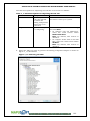
Chapter 1.About this Guide .............................................................................................. 10
Objectives ........................................................................................................................ 11
Audience .......................................................................................................................... 11
How to Use This Manual ................................................................................................. 11
MapuSoft Technologies and Related Documentation ..................................................... 13
Requesting Support .......................................................................................................... 14
Registering a New Account ...................................................................................................... 14
Submitting a Ticket ................................................................................................................... 14
Live Support Offline ................................................................................................................. 15
Documentation Feedback................................................................................................. 15
Chapter 2. Introduction to AppCOE ............................................................................... 16
About AppCOE................................................................................................................ 17
Installing AppCOE........................................................................................................... 18
Uninstalling AppCOE ...................................................................................................... 19
Supported Host Platforms ................................................................................................ 19
Getting a License for AppCOE ........................................................................................ 19
Installing License for AppCOE ....................................................................................... 20
Updating APPCOE .......................................................................................................... 22
Getting Updates for AppCOE ................................................................................................... 22
Updating Software Using Remote Update Site......................................................................... 23
Updating Software Using Local Update Site ............................................................................ 29
Chapter 3. AppCOE Components .................................................................................... 35
Introduction to AppCOE Components............................................................................. 36
AppCOE Architecture ...................................................................................................... 38
OS Simulator.................................................................................................................... 39
Cross-OS development Platform ..................................................................................... 41
Full Library Package Generator ....................................................................................... 42
Optimized Target Code Generator ................................................................................... 42
Ada-C/C++ Changer ........................................................................................................ 43
App/Platform Profiler ...................................................................................................... 43
Chapter 4.Using OS Simulator ......................................................................................... 44
List of Available OS Simulators ...................................................................................... 45
Host Development Environment...................................................................................... 45
Creating an AppCOE C/C++ Project ............................................................................... 47
AppCOE C/C++ Project Template Files ......................................................................... 54
Host System Configuration .............................................................................................. 57
Creating AppCOE C/C++ Project with Multiple Interfaces ............................................ 58
Adding Source Code Files to AppCOE C/C++ Project ................................................... 65
Building Your Project ...................................................................................................... 69
Executing Binary Files ..................................................................................................... 71
Debugging the Demos Supplied by MapuSoft ................................................................ 73
Debugging Using External Console/Terminal ................................................................. 78
Inserting Application Code to Run only on Host Environment ....................................... 83
Updating Project Settings ................................................................................................ 84
Chapter 5. Using OS Changer Porting Kit ...................................................................... 86
About OS Changer ........................................................................................................... 87
Interfaces Available for OS Changer ............................................................................... 88
Using OS Changer ........................................................................................................... 89
2
APPLICATION COMMON OPERATING ENVIRONMENT USER MANUAL
Error Handling ................................................................................................................. 89
Porting VxWorks Applications ........................................................................................ 90
Method 1– Porting a WindRiver Workbench ‘C’ Project ......................................................... 90
Method 2–Porting VxWorks Legacy ‘C’ Code ........................................................................ 96
Method 3– Manually Porting Legacy Applications using Import Feature................................ 98
Porting POSIX/LINUX Legacy ‘C’ Code ....................................................................... 99
Porting Applications from Nucleus PLUS Legacy Code to Target OS ......................... 102
Porting Nucleus Legacy ‘C’ Code ................................................................................. 103
Porting micro-ITRON Legacy ‘C’ Code ....................................................................... 112
Porting Windows Legacy ‘C’ Code ............................................................................... 115
Building OS Abstractor Interface Library ..................................................................... 118
Building OS Abstractor Interface Demo Application ............................................................. 118
OS Changer VxWorks Interface .................................................................................... 118
Building OS Changer VxWorks Interface .............................................................................. 118
Building OS Changer VxWorks Interface Library ................................................................. 118
Building OS Changer VxWorks Interface Demo Application ................................................ 118
OS Changer POSIX/LINUX Interface........................................................................... 118
Building OS Changer POSIX/LINUX Interface ..................................................................... 119
Building OS Changer POSIX/LINUX Interface Library ........................................................ 119
Building OS Changer POSIX/LINUX Interface Demo Application ...................................... 119
OS Changer Nucleus Interface....................................................................................... 119
Building OS Changer Nucleus Interface ................................................................................. 119
Building OS Changer Nucleus Interface Library .................................................................... 119
Building OS Changer Nucleus Interface Demo Application .................................................. 120
OS Changer ThreadX Interface ..................................................................................... 120
Building OS Changer ThreadX Interface................................................................................ 120
Building OS Changer ThreadX Interface Library ................................................................... 120
Building OS Changer ThreadX Interface Demo Application ................................................. 120
Building OS Changer pSOS Interface .................................................................................... 121
Building OS Changer pSOS Interface Library........................................................................ 121
Building OS Changer pSOS Interface Demo Application ...................................................... 121
OS Changer micro-ITRON Interface ............................................................................. 121
Building OS Changer micro-ITRON Interface ....................................................................... 121
Building OS Changer micro-ITRON Interface Library .......................................................... 121
Building OS Changer micro-ITRON Interface Demo Application ........................................ 121
OS Changer Windows Interface .................................................................................... 122
Building OS Changer Windows Interface .............................................................................. 122
Building OS Changer Windows Interface Library.................................................................. 122
Building OS Changer Windows Interface Demo Application ................................................ 122
Building Application with Multiple Interface Components .......................................... 122
Building Application with Multiple Interfaces ....................................................................... 122
Developing Applications with Multiple Interfaces ................................................................. 122
Chapter 6: Using Cross-OS Development platform ..................................................... 124
About Cross-OS Development Platform ....................................................................... 125
About OS Abstractor...................................................................................................... 126
Interfaces Available for OS Abstractor.......................................................................... 126
Full Library Package Generator ..................................................................................... 128
Generating Binary Packages ................................................................................................... 128
Generating Full Library Packages........................................................................................... 128
3
APPLICATION COMMON OPERATING ENVIRONMENT USER MANUAL
Generating Binary Packages ................................................................................................... 133
Optimized Target Code Generator ................................................................................. 134
Generating Optimized Target Code ........................................................................................ 135
Click Apply and OK.Optimized Target Code Generation for Ada Projects ........................... 135
Generating Project Files for your Target ....................................................................... 167
Inserting Application Code to Run only on Target OS Environment ..................................... 168
Running AppCOE Generated Code on your Target ............................................................... 169
Chapter 7.App/Platform Profiler ................................................................................... 170
About App/Platform Profiler ......................................................................................... 171
Opening App/Platform Profiler Perspective .................................................................. 173
Components on the App/Platform Profiler Window ..................................................... 175
Viewing App/Platform Profiler Data ............................................................................. 181
Generating API Timing Report ...................................................................................... 184
Generating Timing Comparison Report......................................................................... 187
Chapter 8. Introduction to Ada C/C++ Changer .......................................................... 191
Ada C/C++ Changer in AppCOE .................................................................................. 192
Creating Ada C/C++ Changer Projects .......................................................................... 192
Creating Ada-C Changer project............................................................................................. 192
Creating Ada-C++ Changer project ........................................................................................ 193
Creating New Ada-C Template project: ................................................................................. 194
Creating Ada-C++ Template project: ..................................................................................... 195
Ada Source Directory .................................................................................................... 197
Configuration with Linked Libraries ............................................................................. 197
Specifying the Configuration ......................................................................................... 197
ADA.LIB and UNIT.MAP ............................................................................................ 197
Program Library Options Tool (adaopts) ....................................................................... 200
Source Registration Tool (adareg) ................................................................................. 200
Adacgen ......................................................................................................................... 201
Compiler Output Files.................................................................................................... 205
Adabgen ......................................................................................................................... 205
Program Builder Processing .......................................................................................... 206
Adabgen Inputs .............................................................................................................. 206
Ada C/C++ Changer Outputs ......................................................................................... 208
Chapter 9.Working with Ada Changer ......................................................................... 209
Ada C Changer Projects with Ada-C/C++ Scheduling .................................................. 209
Working with Ada C/C++ Changer Projects ................................................................. 210
Ada C Changer Projects with Ada-C/C++ Scheduling .................................................. 211
Ada C Changer Projects with Real-time OS Abstractor Scheduling ............................. 211
Select Ada-C/C++ Changer build configurations .......................................................... 212
Import Ada Source files to project ................................................................................. 213
ADA C/C++ Changer Configuration Options ............................................................... 215
Target Code Generation for Ada C/C++ Changer Projects ........................................... 229
Ada C/C++ Changer Property Page ............................................................................... 231
ADA C/C++ Changer – Additional Information’s ........................................................ 233
Additional Ada C/C++ Changer tools: .......................................................................... 234
Revision History ............................................................................................................... 235
4
APPLICATION COMMON OPERATING ENVIRONMENT USER MANUAL
List Of Figures
Figure 1_1: Create a Support Ticket from AppCOE ............................................................... 14
Figure 2_1: Importing License................................................................................................. 20
Figure 2_2: Selecting the Saved License File .......................................................................... 21
Figure 2_3: Software Updates Using Remote Site .................................................................. 23
Figure 2_4: Check the Available Updates ............................................................................... 24
Figure 2_5: Contacting Software Sites for Updates ................................................................ 25
Figure 2_6: Review and Confirm the Updates ........................................................................ 25
Figure 2_7: Remote Update Host Target Feature License....................................................... 26
Figure 2_8: Remote Updates Download .................................................................................. 26
Figure 2_9: Security Warning .................................................................................................. 27
Figure 2_10: Updating Software .............................................................................................. 27
Figure 2_11: Restart AppCOE ................................................................................................. 28
Figure 2_12: Confirmation of new features installed .............................................................. 28
Figure 2_13: Software Updates Using Local Site.................................................................... 29
Figure 2_14: AppCOE Software Updates................................................................................ 30
Figure 2_15: Installing Updates by Using Local Update Site ................................................. 30
Figure 2_16: Available Software Sites .................................................................................... 31
Figure 2_17: Contacting Software Sites for Updates .............................................................. 31
Figure 2_17: Review and confirm the Updates ....................................................................... 32
Figure 2_18: Remote Update Host Target Feature License..................................................... 32
Figure 2_19: Remote Updates Download ................................................................................ 33
Figure 2_20: Security Warning ................................................................................................ 33
Figure 2_21: Restart AppCOE ................................................................................................. 34
Figure 2_22: Confirmation of new features installed .............................................................. 34
Figure 3_1: AppCOE Components .......................................................................................... 37
Figure 3_2: AppCOE Architecture .......................................................................................... 38
Figure 3_3: OS Changer Porting kit ........................................................................................ 40
Figure 3_4: Cross-OS development Platform .......................................................................... 41
Figure 4_1: Creating an AppCOE C Project............................................................................ 47
Figure 4_2: AppCOE C Project Wizard Window................................................................... 48
Figure 4_3: Basic Settings Window ........................................................................................ 49
Figure 4_4: Configurations Window ....................................................................................... 50
Figure 4_5: Select APIs Window ............................................................................................ 51
Figure 4_6: Select Host Library Configuration Window ........................................................ 52
Figure 4_7: Creating AppCOE C/C++ Project Output ............................................................ 53
Figure 4_8: AppCOE C/C++ Project Template Files .............................................................. 54
Figure 4_9: Creating a Project with Multiple Interfaces ......................................................... 58
Figure 4_10: AppCOE C Project Wizard Window.................................................................. 59
Figure 4_11: Basic Settings Window ...................................................................................... 60
Figure 4_12: Configurations Window ..................................................................................... 61
Figure 4_13: Select APIs Window. ......................................................................................... 62
Figure 4_15: A Project with multiple Interfaces Output ......................................................... 64
Figure 4_16: Adding Source Code Files .................................................................................. 65
Figure 4_17: Importing Files from Local File System ............................................................ 66
Figure 4_18: Importing Source Code Files from Directory..................................................... 67
Figure 4_19: Selecting Source Code Files for Importing ........................................................ 67
Figure 4_20: Importing Source Code Files Output.................................................................. 68
Figure 4_21: Building Your Project ........................................................................................ 69
5
APPLICATION COMMON OPERATING ENVIRONMENT USER MANUAL
Figure 4_22: Output for Building Binary Files for a Project ................................................... 70
Figure 4_23: Executing the Binary File ................................................................................... 71
Figure 4_24: Binary Output ..................................................................................................... 72
Figure 4_25: Debugging the Demo Application ...................................................................... 73
Figure 4_29: Resume Debugging process ............................................................................... 75
Figure 4_30: Debug Demo Application Perspective ............................................................... 76
Figure 4_31: Debug Demo Application Output....................................................................... 76
Figure 4_32: Debug Demo Application Using AppCOE ........................................................ 77
Figure 4_33: Resume Debugging process .............................................................................. 77
Figure 4_34: Open Debug Dialog ............................................................................................ 78
Figure 4_35: Debug Configuration Window ........................................................................... 79
Figure 4_36: Debugging Output Using External Console/Terminal ....................................... 80
Figure 4_37: Resume Debugging Using External Console/Terminal ..................................... 81
Figure 4_38: Debugging in Progress ....................................................................................... 82
Figure 4_39: Updating Project Settings ................................................................................... 84
Figure 4_40: AppCOE C/C++ Project Updates ....................................................................... 85
Figure 5_1: About OS Changer ............................................................................................... 87
Figure 5_2: OS Changer Flow Diagram .................................................................................. 88
Figure 5_3: Importing a VxWorks Workbench ‘C’ Project in AppCOE ................................ 90
Figure 5_4: AppCOE Import Window .................................................................................... 91
Figure 5_5: Application Startup Files Window ....................................................................... 92
Figure 5_6: Provide Inputs for Projects Window .................................................................... 93
Figure 5_7: Porting Reports Page ............................................................................................ 93
Figure 5_8: Porting Reports Page Guidelines .......................................................................... 94
Figure 5_9: Project Perspective of the Ported Projects ............................................................ 95
Figure 5_10: Importing VxWorks Legacy ‘C’ Code in AppCOE ........................................... 96
Figure 5_11: Import Legacy Code Window ............................................................................ 97
Figure 5_12: Porting POSIX/LINUX Legacy ‘C’ Code in AppCOE...................................... 99
Figure 5_13: Import POSIX/LINUX Legacy Code Window ................................................ 100
Figure 5_14 : Importing POSIX/LINUX Legacy Code Output............................................. 101
Figure 5_15: Porting Nucleus PLUS Applications ................................................................ 102
Figure 5_16 : Importing Nucleus Legacy ‘C’ Code in AppCOE .......................................... 103
Figure 5_17: Import Nucleus Legacy Code Window ............................................................ 104
Figure 5_18: Importing Nucleus Code Output ...................................................................... 105
Figure 5_19: Importing ThreadX Legacy ‘C’ Code in AppCOE .......................................... 106
Figure 5_20: Import Threadx Legacy Code Window ............................................................ 107
Figure 5_21: Importing Threadx Code Output ...................................................................... 108
Figure 5_22: Importing pSOS Legacy ‘C’ Code in AppCOE ............................................... 109
Figure 5_23: Import pSOS Legacy Code Window ................................................................ 110
Figure 5_24: Importing pSOS Legacy Code Output ............................................................. 111
Figure 5_25: Importing micro-ITRON Legacy ‘C’ Code in AppCOE.................................. 112
Figure 5_26: Import micro-ITRON Legacy Code Window .................................................. 113
Figure 5_27: Importing micro-ITRON Legacy Code Output ................................................ 114
Figure 5_28: Importing Windows Legacy ‘C’ Code in AppCOE ......................................... 115
Figure 5_29 : Import Windows Legacy Code........................................................................ 116
Figure 5_30: Importing Windows Legacy Code Output ....................................................... 117
Figure 6_1: Cross-OS Development Platform ....................................................................... 125
Figure 6_2: OS Abstractor Flow Diagram ............................................................................. 126
Figure 6_3: Generating Library Package ............................................................................... 128
Figure 6_4: Select Target OS ................................................................................................. 129
6
APPLICATION COMMON OPERATING ENVIRONMENT USER MANUAL
Figure 6_5: Select OS Changer or OS Abstractor Products .................................................. 130
Figure 6_6: Select Destination Path ....................................................................................... 131
Figure 6_7: Full Library Package Generation Verification Report ....................................... 132
Figure 6_8: Full Library Package Generation Folder ............................................................ 133
Figure 6_9: AppCOE Target Code Generator ....................................................................... 136
Figure 6_10: Selected VxWorks Target in this Example ...................................................... 137
Figure 6_11: Select the linked-in Libraries ........................................................................... 139
Figure 6_12: Profiler Configuration ...................................................................................... 140
Figure 6_13: Platform API Profiling ..................................................................................... 142
Figure 6_14: Application Function Profiling ......................................................................... 144
Figure 6_15: API Optimization ............................................................................................. 146
Figure 6_16: Task Tab ........................................................................................................... 148
Figure 6_18: Memory Tab ..................................................................................................... 152
Figure 6_19: Other Resources Tab ........................................................................................ 154
Figure 6_20: Debug Tab ........................................................................................................ 156
Figure 6_21: Output Devices Tab .......................................................................................... 158
Figure 6_22: ANSI Mapping Tab .......................................................................................... 160
Figure 6_23: Device Input or Output Tab.............................................................................. 162
Figure 6_24: Interface Tab..................................................................................................... 164
Figure 6_25: Target Code Generation Output ....................................................................... 165
Figure 6_26: AppCOE Generated Example .......................................................................... 166
Figure 6_27: Generating Project Files ................................................................................... 167
Figure 7_2: Opening App/Platform Profiler Perspective....................................................... 173
Figure 7_3: App/Platform Profiler Perspective ..................................................................... 174
Figure 7_4: App/Platform Profiler - System Details ............................................................. 175
Figure 7_5: App/Platform Profiler System ............................................................................ 176
Figure 7_6: Platform APIs and Application Functions.......................................................... 177
Figure 7_7: Platform APIs ..................................................................................................... 178
Figure 7_8: Application – Functions ..................................................................................... 179
Figure 7_9: App/Platform Profiler – Threads ........................................................................ 180
Figure 7_10: Viewing AppCOE Profiler Data....................................................................... 181
Figure 7_11: Selecting the .pal File Extension to Analyze .................................................... 182
Figure 7_12: Selecting the API to view the Profiler Data ..................................................... 183
Figure 7_13: Generate Timing Report ................................................................................... 184
Figure 7_14: Saving the Timing Report ................................................................................ 185
Figure 7_15: Generate Timing Comparison Report .............................................................. 187
Figure 7_16: Import PAL File ............................................................................................... 188
Figure 7_17: Selecting the APIs ............................................................................................ 189
Figure 7_18: Saving Timing Comparison Report .................................................................. 190
Figure 7_19: Generated Timing Comparison Report ............................................................ 190
Figure 8_1: Ada-C Changer project ...................................................................................... 192
Figure 8_2: Ada-C++ Changer project ................................................................................. 193
Figure 8_3: Create Ada-C Template ..................................................................................... 194
Figure 8_4: Create Ada-C++ Template ................................................................................ 195
Figure 8_5: Import Ada Files ................................................................................................ 196
Figure 9_1: Creating Ada-C Changer Project ........................................................................ 210
Figure 9_2: Ada-C/C++ Changer Wizard .............................................................................. 211
Figure 9_3: Basic Settings Window for Ada-C/C++ Changer Project .................................. 212
Figure 9_4: Select Ada-C/C++ Changer build configurations .............................................. 212
Figure 9_5: Import Ada Source files to project ..................................................................... 213
7
APPLICATION COMMON OPERATING ENVIRONMENT USER MANUAL
Figure 9_6: C/C++ Output Page ............................................................................................ 215
Figure 9_7: Ada Listings Tab ................................................................................................ 217
Figure 9_8: Ada Messages Tab.............................................................................................. 219
Figure 9_9: Ada Drivers Tab ................................................................................................. 221
Figure 9_10: Additional Options Tab .................................................................................... 222
Figure 9_11: OS Abstractor Integration Page ........................................................................ 223
Figure 9_12: Ada-C Project Report Page ............................................................................. 224
Figure 9_13: Output for Ada- C/C++Changer ....................................................................... 225
Figure 9_14: Build Project ..................................................................................................... 227
Figure 9_15: Building Ada-C/C++Changer project .............................................................. 228
Figure 9_16: Generated .exe File ........................................................................................... 229
Figure 9_17: Ada C/C++ Changer Properties........................................................................ 231
Figure 9_18: Ada C/C++ Changer Property Page ................................................................ 232
8
APPLICATION COMMON OPERATING ENVIRONMENT USER MANUAL
List of Tables
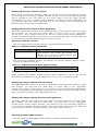
Table 1_1: Notice Icons ........................................................................................................... 12
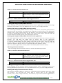
Table 1_2: Text and Syntax Conventions ................................................................................ 12
Table 1_3: Document Description Table ................................................................................. 13
Table 4_1: OS HOST Selection ............................................................................................... 83
Table 4_2: Target 64 bit CPU Selection .................................................................................. 83
Table 5_1: VxWorks Interface Header File ........................................................................... 118
Table 5_2: VxWorks Interface Demo Application File ........................................................ 118
Table 5_3: Posix Interface Header File ................................................................................. 119
Table 5_4: POSIX/LINUX Interface Demo Application File .............................................. 119
Table 5_5: Nucleus Interface Header File ............................................................................. 119
Table 5_6: Nucleus Interface Demo Application File .......................................................... 119
Table 5_7: ThreadX Interface Header File ............................................................................ 120
Table 5_8: Nucleus Interface Demo Application File .......................................................... 120
Table 5_9: pSOS Interface Header File ................................................................................. 120
Table 5_10: pSOS Interface Demo Application File ............................................................ 121
Table 5_11: OS Changer micro-ITRON Interface Header File ............................................. 121
Table 5_12: OS Changer micro-ITRON Interface Demo Application File ........................... 121
Table 5_13: OS Changer Windows Interface Header File .................................................... 122
Table 5_14: Windows Interface Demo Application File ...................................................... 122
Table 6_2: Field descriptions on Profiler Configuration tab ................................................. 141
Table 6_3: Field descriptions on Platform API Profiling tab ................................................ 143
Table 6_4: Field descriptions on Application Functions Profiling tab .................................. 145
Table 6_5: Field descriptions on API Optimization tab ........................................................ 147
Table 6_6:Field descriptions on Task tab .............................................................................. 149
Table 6_7: Field descriptions on Process tab ......................................................................... 151
Table 6_8: Field descriptions on Memory tab ....................................................................... 153
Table 6_9: Field descriptions on Other Resources tab .......................................................... 155
Table 6_10: Field descriptions on Debug tab ........................................................................ 157
Table 6_11: Field descriptions on Output Devices tab .......................................................... 159
Table 6_12: Field descriptions on ANSI Mapping tab .......................................................... 161
Table 6_13: Field descriptions on Device I/O tab ................................................................. 163
Table 6_14: Field descriptions on Interface tab ..................................................................... 165
Table 6_15: Target OS Selection ........................................................................................... 168
Table 7_1: Field descriptions for importing the PAL file ..................................................... 189
Table 8_1: Compiler Generates the Requested listing Options for Each File ....................... 201
Table 8_2: adacgen Options................................................................................................... 202
Table 8_3: Options For Maintainers ...................................................................................... 204
Table 8_4: Compiler Output Files ......................................................................................... 205
Table 8_5: Additional Compiler Output Files ....................................................................... 205
Table 8_5: adabgen Options .................................................................................................. 207
Table 9_1: Field Descriptions for Import Ada Files .............................................................. 214
Table 9_2: Field Descriptions for C/C++ Output tab ............................................................ 216
Table 9_3: Field Descriptions for Ada Listings tab ............................................................... 218
Table 9_4: Field Descriptions for Ada Messages tab ............................................................ 220
Table 9_5: Field Descriptions for Ada Drivers Options tab .................................................. 221
Table 9_6: Field Descriptions for Additional Options tab..................................................... 222
9
APPLICATION COMMON OPERATING ENVIRONMENT USER MANUAL
Chapter 1.About this Guide
This chapter contains the following topics:
Objectives
Audience
How to Use This Manual
Document Conventions
MapuSoft Technologies and Related Documentation
Requesting Support
Documentation Feedback
10
APPLICATION COMMON OPERATING ENVIRONMENT USER MANUAL
Objectives
This manual describes about AppCOE IDE and offers information on porting your
application to different toolsets and platforms, and information on how to use our
functionality and learn our user interface (UI). AppCOE provides a multiple OS interface
host environment with provisions to generate optimized code for a wide variety of target OS
platforms.
Topics in this manual also apply to the other MapuSoft‘s interfaces supported by OS
Changer which allows you to re-use a wide variety of legacy code such as VxWorks, pSOS,
Nucleus PLUS, POSIX/LINUX, Windows, uITRON, ThreadX.
Audience
This manual is designed for anyone who wants to port applications to different operating
systems, create projects, and run applications. This manual is intended for the following
audiences:
Customers with technical knowledge and experience with the Embedded Systems
Application developers who want to migrate their application to different RTOSs
Managers who want to minimize the cost and leverage on their existing code
How to Use This Manual
This manual and the other MapuSoft Technologies manuals explain how to port and
migrate applications to different operating systems.
The organization of this document is as described below:
Using these documents you can
Develop & Port legacy applications.
Generate code optimization & target code generation.
Generate Full Library Package OS Abstractor/OS Changer Packages
Enable Application profiling and platform profiling
Convert Ada 83/95 applications to C/C++
11
APPLICATION COMMON OPERATING ENVIRONMENT USER MANUAL
Document Conventions
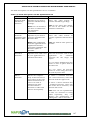
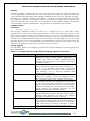
Table 1_1 defines the notice icons used in this manual.
Table 1_1: Notice Icons
Icon
Meaning
Informational note
Caution
Description
Indicates important features
or icons.
Indicates a situation that
might result in loss of data or
software damage.
Table 1_2 defines the Text and Syntax conventions used in this manual.
Table 1_2: Text and Syntax Conventions
Convention
Courier New
Italic text like this
COURIER NEW,ALL CAPS
Courier New, Bold
Description
Identifies
Program
listings
and
Program
examples.
Introduces important new
terms.
Identifies book names
Identifies Internet draft
titles.
Identifies File names.
Identifies
Interactive
Command lines
12
APPLICATION COMMON OPERATING ENVIRONMENT USER MANUAL
MapuSoft Technologies and Related Documentation
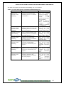
Reference manuals can be provided under NDA. Click http://mapusoft.com/contact/ to request for
a reference manual. The document description table lists MapuSoft Technologies manuals.
Table 1_3: Document Description Table
User Guides
Description
System Configuration Guide
Provides detailed description on the system
configuration to work with MapuSoft products. This
guide:
Describes
the
system
requirements
and
configurations to get started with MapuSoft
Technologies products
Provides detailed description on how to become familiar
with AppCOE product and use it with ease. This guide:
AppCOE Quick Start Guide
OS Abstractor
Reference Manual
Interface
VxWorks Interface Reference
Manual
POSIX Interface Reference
manual
pSOS Interface
Manual
Reference
pSOS
Classic
Reference Manual
Interface
Nucleus Interface Reference
Manual
Micro-ITRON
Reference Manual
Interface
ThreadX Interface Reference
Manual
Explains how to quickly set-up AppCOE on
Windows/Linux Host and run the demos that came
along AppCOE
Provides detailed description of how to use OS
Abstraction. This guide:
Explains how to develop code independent of the
underlying OS
Explains how to make your software easily support
multiple OS platforms
Provides detailed description of how to get started
with VxWorks interface support that MapuSoft
provides. This guide:
Explains how to use VxWorks interface, port
applications
Provides detailed description of how to get started
with POSIX interface support that MapuSoft provides.
This guide:
Explains how to use POSIX interface, port
applications
Provides detailed description of how to get started
with pSOS interface support that MapuSoft provides.
This guide:
Explains how to use pSOS interface, port
applications
Provides detailed description of how to get started
with pSOS Classic interface support that MapuSoft
provides. This guide
Explains how to use pSOS Classic interface, port
applications
Provides detailed description of how to get started
with Nucleus interface support that MapuSoft
provides. This guide:
Explains how to use Nucleus interface, port
applications
Provides detailed description of how to get started
with uITRON interface support that MapuSoft
provides. This guide:
Explains how to use uITRON interface, port
applications
Provides detailed description of how to get started
with ThreadX interface support that MapuSoft
13
APPLICATION COMMON OPERATING ENVIRONMENT USER MANUAL
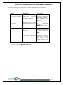
User Guides
Windows Interface Reference
Manual
Release Notes
Description
provides. This guide:
Explains how to use ThreadX interface, port
applications
Provides detailed description of how to get started
with Windows interface support that MapuSoft
provides. This guide:
Explains how to use Windows interface, port
applications
Provides the updated release information about
MapuSoft Technologies new products and features for
the latest release.
This document:
Gives detailed information of the new products
Gives detailed information of the new features added
into this release and their limitations, if required
Requesting Support
Technical support is available through the MapuSoft Technologies Support Centre. If you
are a customer with an active MapuSoft support contract, or covered under warranty, and
need post sales technical support, you can access our tools and resources online or open a
ticket at http://www.mapusoft.com/support.
Registering a New Account
To register:
From http://www.mapusoft.com/main page, select Support.
Select Register and enter the required details.
After furnishing all your details, click Submit.
Submitting a Ticket
1. To submit a ticket:
1. From http://www.mapusoft.com/main page, select Support > Submit a
Ticket
2. Select a department according to your problem, and click Next.
3. Fill in your details and provide detailed information of your problem.
4. Click Submit.
MapuSoft Support personnel will get back to you within 48 hours with a valid response.
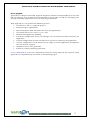
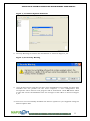
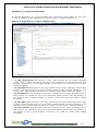
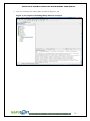
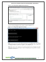
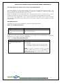
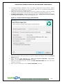
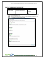
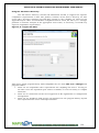
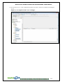
2. To submit a ticket from AppCOE
From AppCOE main menu, Select Help > Create a Support Ticket as shown in
Figure 1_1.
Figure 1_1: Create a Support Ticket from AppCOE
14
APPLICATION COMMON OPERATING ENVIRONMENT USER MANUAL
1. Using the Existing Email and Password for login into Mapusoft Support
Suite.
2. Select the department according to your problem, and click Next.
3. Fill in your details and provide detailed information of your problem.
4. Click Submit.
MapuSoft Support personnel will get back to you within 48 hours with a valid response.
Live Support Offline
MapuSoft Technologies also provides technical support through Live Support offline.
To contact live support offline:
1. From http://www.mapusoft.com/main page, select Support > Live
Support Offline.
2. Enter your personal details in the required fields. Enter a message about
your technical query. One of our support personnel will get back to you as
soon as possible.
3. Click Send.
You can reach us at our toll free number: 1-877-627-8763 for any urgent assistance.
Documentation Feedback
Send Feedback on Documentation: http://www.mapusoft.com/support/index.php/
15
APPLICATION COMMON OPERATING ENVIRONMENT USER MANUAL
Chapter 2. Introduction to AppCOE
This chapter contains the following topics:
About AppCOE
Installing AppCOE
Uninstalling AppCOE
Supported Host Platforms
Getting a License for AppCOE
Installing License for AppCOE
Updating APPCOE
16
APPLICATION COMMON OPERATING ENVIRONMENT USER MANUAL
About AppCOE
AppCOE is an Eclipse based IDE. AppCOE integrates software interoperability & reuse tools
like OS Changer and OS Abstractor with Eclipse‘s CDT to offer an IDE for developing and
porting embedded applications on many host/target platforms.
With AppCOE you can perform the following actions:
Creation of C and C++ AppCOE projects
Porting of legacy applications
Host development with simulation for many OS applications
Converting Ada source code to C/C++ code
Platform and Application profiling
Automatic configuration of any OS Changer and OS Abstractor APIs needed by the
application
Custom configuration of OS & OS Abstractor resources needed by the application
Custom configuration of OS Abstractor for single or multi-application development
(Process Feature support)
Optimized source code generation
Full Source Library Package generation
Contact MapuSoft to receive the components needed for using AppCOE. The steps for using
AppCOE are comprehensively described in the following pages.
17
APPLICATION COMMON OPERATING ENVIRONMENT USER MANUAL
Installing AppCOE
You can download an evaluation copy from our website or install AppCOE via the
evaluation CD given by MapuSoft Technologies.
To install AppCOE:
1. Click on the exe or tar file from CD/download and run it. A welcome html page will
be auto run
2. Select Host
For Windows Host,
1. For
Ada-C/C++
Changer™
Product,
download
appcoe_x32.exe
or
appcoe_x64.exe into the local drive
2. For OS Changer® Porting Kit, Cross-OS Development Platform™, Cross-OS
Hypervisor™, Linux OK™, OS Simulator™, App/Platform Profiler™, OS Version
UpKit™ products, download either appcoe_x32.exe or appcoe_x64.exe
depending on the host machine CPU architecture
3. Installer will ask for a directory to install AppCOE release. Browse to the
directory or provide a directory name when prompted
4. Once AppCOE is installed, reboot the system. AppCOE will not run properly
without re-boot
5. Now, Run the AppCOE.exe in AppCOE <installdir> or launch the AppCOE
application from the windows shortcut in desktop
For Linux Host,
1. For Ada-C/C++ Changer™ Product, download app-coe-linux_x32.tar.gz into the
local drive
2. For OS Changer® Porting Kit, Cross-OS Development Platform™, Cross-OS
Hypervisor™, Linux OK™, OS Simulator™, App/Platform Profiler™, OS Version
UpKit™ products, download either app-coe-linux_x32.tar.gz or app-coelinux_x64.tar.gz depending on the host machine CPU architecture
3. Extract the tar file app-coe-linux_x32.tar.gz or app-coe-linux_x64.tar.gz. You
will get install.sh & app-coe-linux.bin
4. Run the install.sh program, it will check for dependency needed for installing
AppCOE, Install the missing dependencies and try running this script again, If
no dependencies is found, AppCOE installer will start
5. Installer will ask for a directory to install AppCOE release, Browse to the
directory <installdir> or provide a directory name when prompted (ensure that
the logged-in user has full read/write/execute privileges to in this install
directory)
6. After AppCOE gets installed, install.sh will check for AppCOE dependencies.
Install the missing dependencies if any
7. Then run app-coe-linux.bin to launch the AppCOE installer.
8. Repeat steps 2-4 as in the Linux host
NOTE:
For Windows Host:
By default, it is c:\MapuSoft\AppCOE.
For Linux Host:
By default path is /usr/local/AppCOE
Do not provide special characters to the <installdir> as you will get java run-time errors.
AppCOE may have problems with paths containing spaces, and if not, usually other
programs used with AppCOE will experience problems with such paths.
18
APPLICATION COMMON OPERATING ENVIRONMENT USER MANUAL
Uninstalling AppCOE
To uninstall AppCOE:
1. Browse to the installed AppCOE directory and start the Uninstall application.
2. For Windows only, You can also uninstall AppCOE by selecting Control Panel>
Add/Remove Programs. Select AppCOE and click Remove.
3. There is a possibility of user generated/modified files to be left on your AppCOE
installation directory. If not necessary, delete the files manually to remove the files.
Supported Host Platforms
AppCOE supports the following host platforms:
Windows XP/7 /8
Linux
Supported Development APIs:
Cross-OS: OS Abstractor* Interface
*supports Windows 2000, Windows XP, Windows CE, Windows Vista, Android,
Linux, MQX, NetBSD, Nucleus PLUS, QNX, Solaris, ThreadX, uCOS, micro-ITRON,
VxWorks, ecos , T-Kernel , LynxOS , LynxOS , QNX ,UCOS target operating
systems.
Cross-OS: OS Abstractor POSIX/LINUX Interface
Cross-OS: OS Abstractor UITRON Interface
OS Changer: Nucleus Interface
OS Changer: pSOS Interface (1.4 Revision & 2.x Revision)
OS Changer: ThreadX Interface
OS Changer: VxWorks Interface
OS Changer: Windows Interface
For a list of AppCOE supported target operating systems, click here: www.mapusoft.com/
Getting a License for AppCOE
AppCOE is licensed by the following host and target licenses. A 30 day advanced evaluation
license is available for the host licenses. Click www.mapusoft.com/downloads/ to request
an evaluation license.
19
APPLICATION COMMON OPERATING ENVIRONMENT USER MANUAL
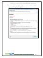
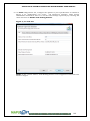
Installing License for AppCOE
MapuSoft provides a license key to the customers. Once the customers provide the Mac
Address of their system, MapuSoft Technologies provides a License key for that particular
system. This establishes security for the license.
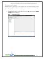
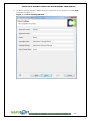
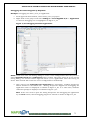
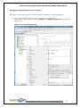
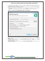
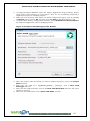
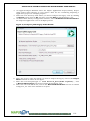
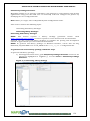
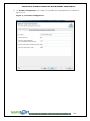
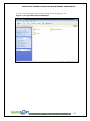
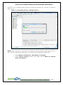
To install the license:
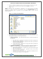
1. Save the license file given to you by MapuSoft.
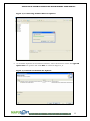
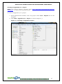
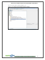
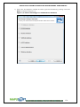
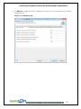
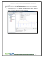
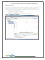
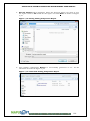
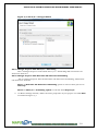
2. On AppCOE main menu, click the down arrow next to Key button and select Install
License as shown in Figure 2_1.
Figure 2_1: Importing License
20
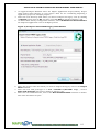
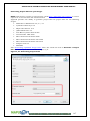
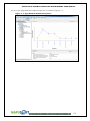
APPLICATION COMMON OPERATING ENVIRONMENT USER MANUAL
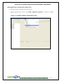
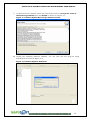
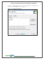
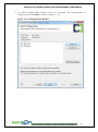
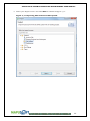
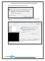
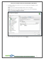
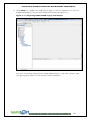
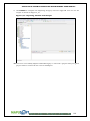
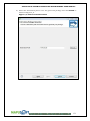
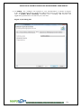
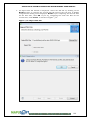
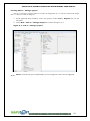
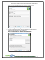
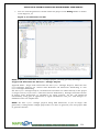
3. Browse to the location of the saved license file, click Open as shown in Figure 2_2.
The license key is installed and now you can work on AppCOE.
Figure 2_2: Selecting the Saved License File
21
APPLICATION COMMON OPERATING ENVIRONMENT USER MANUAL
Updating APPCOE
Getting Updates for AppCOE
NOTE:
This
feature
requires
AppCOE
Host
License.
Click
http://www.mapusoft.com/contact/ to send a request to receive licenses and
documentation.
You can get latest AppCOE updates from http://www.mapusoft.com using the following two
options:
Remote Update: By using Remote Update Site, the system will automatically contact
http://www.mapusoft.com/ website and search for the latest updates. You need
internet connectivity for this to work
Local Update: By using Local Update Site, you can do AppCOE updates without
connecting to the Internet. For this to work, you need to get the updated files from
http://www.mapusoft.com/ by e-mail or CD
22
APPLICATION COMMON OPERATING ENVIRONMENT USER MANUAL
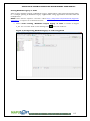
Updating Software Using Remote Update Site
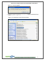
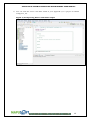
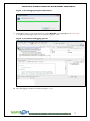
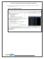
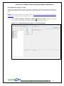
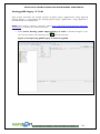
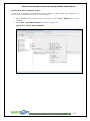
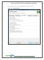
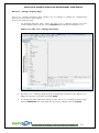
To update software using Remote update site:
1. From AppCOE main menu, select Help >Check for Updates as shown in
Figure
2_3.
Figure 2_3: Software Updates Using Remote Site
23
APPLICATION COMMON OPERATING ENVIRONMENT USER MANUAL
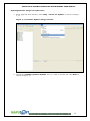
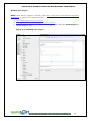
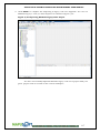
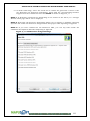
2. Check the Available Updates that you wish to install as shown in Figure 2_4.
Figure 2_4: Check the Available Updates
3. Contacting Software Sites for Updates as shown in Figure 2_5.
24
APPLICATION COMMON OPERATING ENVIRONMENT USER MANUAL
Figure 2_5: Contacting Software Sites for Updates
4. On Available Updates Search Results window, select the features under the AppCOE
Update Site tree parent and click Next as shown in Figure 2_6.
Figure 2_6: Review and Confirm the Updates
25
APPLICATION COMMON OPERATING ENVIRONMENT USER MANUAL
5. On Review License window, select the radio button next to I accept the terms in
the license agreements and click Finish as shown in Figure 2_7.
Figure 2_7: Remote Update Host Target Feature License
6. During the Updating Software Window, you can view the new plug-ins being
downloaded as shown in Figure 2_8.
Figure 2_8: Remote Updates Download
26
APPLICATION COMMON OPERATING ENVIRONMENT USER MANUAL
7. Security Warning in between the Installation as shown in Figure 2_9.
Figure 2_9: Security Warning
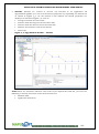
8. After press ok , Installation Continue as shown in Figure 2_10.
Figure 2_10: Updating Software
9. Once all the features and plug-ins have been downloaded successfully and their files
installed into the product on the local computer, a new configuration that
incorporates these features & plug-ins will be formulated. Click yes when asked to
exit and restart the Workbench for the changes to take effect as shown in Figure
2_11.You have now successfully installed new feature updates to your AppCOE
using the Remote Update Site.
27
APPLICATION COMMON OPERATING ENVIRONMENT USER MANUAL
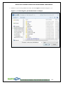
Figure 2_11: Restart AppCOE
10. Check the new features installed correctly from the AppCOE installed directory >
plugins as shown in Figure 2_12.
Figure 2_12: Confirmation of new features installed
28
APPLICATION COMMON OPERATING ENVIRONMENT USER MANUAL
Updating Software Using Local Update Site
1. From AppCOE main window, select Help > Check for Updates as shown in Figure
2_13.
Figure 2_13: Software Updates Using Local Site
2. Check the Available Updates windows that you wish to install and click Next as
shown in Figure 2_1.
29
APPLICATION COMMON OPERATING ENVIRONMENT USER MANUAL
Figure 2_14: AppCOE Software Updates
On Updates sites to visit window, select Add and browse for the folder provided by
MapuSoft, named as mapusoft.AppCOE.updatesite and click OK as shown in Figure 2_15.
NOTE: If the system does not allow you to give the same site name, select the previous
update site folder from the list and click Remove. Or, you can also save the Update site
folder in any other location on your local disk.
Figure 2_15: Installing Updates by Using Local Update Site
30
APPLICATION COMMON OPERATING ENVIRONMENT USER MANUAL
3. On Edit Local Site pop up window, next to Name text box, provide a different name
and click OK. The name can be any name that is not already present on the list as
shown in Figure 2_16.and click OK.
Figure 2_16: Available Software Sites
4. Contacting Software Sites for Updates as shown in Figure 2_16.
Figure 2_17: Contacting Software Sites for Updates
31
APPLICATION COMMON OPERATING ENVIRONMENT USER MANUAL
5. On Available Updates Window, select the features under the AppCOE Update Site
tree parent and click Next as shown in Figure 2_17.
Figure 2_17: Review and confirm the Updates
6. On Available Updates window, select the radio button next to I accept the terms in
the license agreements and click Finish as shown in Figure 2_18.
Figure 2_18: Remote Update Host Target Feature License
7. During the Updating Software Window, you can view the new plug-ins being
downloaded as shown in Figure 2_19 .
32
APPLICATION COMMON OPERATING ENVIRONMENT USER MANUAL
Figure 2_19: Remote Updates Download
8. Security Warning in between the Installation as shown in Figure 2_20 .
Figure 2_20: Security Warning
9. Once all the features and plug-ins have been downloaded successfully and their files
installed into the product on the local computer, a new configuration that
incorporates these features and plug-ins will be formulated. Click Yes when asked
to exit and restart the Workbench for the changes to take effect as shown in Figure
2_27.
10. You have now successfully installed new feature updates to your AppCOE using the
Remote Update Site.
33
APPLICATION COMMON OPERATING ENVIRONMENT USER MANUAL
Figure 2_21: Restart AppCOE
11. Check the new features installed correctly from the AppCOE installed directory >
plugins as shown Figure 2_22.
Figure 2_22: Confirmation of new features installed
34
APPLICATION COMMON OPERATING ENVIRONMENT USER MANUAL
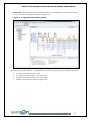
Chapter 3. AppCOE Components
This chapter introduces all the AppCOE components. They are as follows:
Introduction to AppCOE Components
AppCOE Architecture
OS Simulator
OS Changer Porting kit
Cross-OS development Platform Error! Reference source not found.
Optimized Target Code Generator
Ada-C/C++ Changer
App/Platform Profiler
35
APPLICATION COMMON OPERATING ENVIRONMENT USER MANUAL
Introduction to AppCOE Components
With Application Common Operating Environment (AppCOE) you can easily port, abstract
and optimize your code on a host machine and run the application on different target
platforms. AppCOE leverages the existing OS Changer and OS Abstractor technologies while
adding advanced code optimization capacities on multiple OS environments. AppCOE
provides users an easy-to-use graphical user interface that is integrated with the Eclipse®
based CDT environment.
AppCOE uses OS Abstractor and OS Changer technology to produce Cross-OS
development platform for many targets . AppCOE target features include:
Porting of legacy applications to your new chosen OS (OS Changer Porting Kit)
Development of embedded applications on Host environment (OS Simulator)
Convert Ada source code to C/C++ code (Ada-C/C++ Changer)
Application profiling and platform profiling for your APIs (App/Platform Profiler)
Generate API Profiling timing report and Profiling Timing comparison report
(App/Platform Profiler)
Cross-OS Development Platform Features that includes:
o Automatic configuration of any OS Changer and OS Abstractor APIs
needed by the application
o Custom configuration of OS & OS Abstractor resources needed by the
application
o Custom configuration of OS Abstractor for single or multi-application
development (Process Feature support)
o Full Source Library Package generation
o
Generation of project files for your IDE
o
Generated target code is optimized to contain only the APIs used by the
application
o
Allows for further optimization by in-lining user selected API‘s
o
Enables to convert Ada source code into C/C++ code
Target selection and configuration tabs to optimize the target code specific for
your application
o
Target OS selection
o
Profiler configuration
o
Task configuration including a task pooling feature
o
Process configuration including a process feature
o
Memory configuration
o
Resource configuration
o
Debug configuration
o
Output configuration including the ability to output to a console or serial
port
o
ANSI Mapping configuration
o
Device I/O configuration
36
APPLICATION COMMON OPERATING ENVIRONMENT USER MANUAL
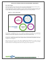
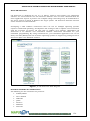
MapuSoft provides an illustration to describe all the components of AppCOE. AppCOE
leverages the existing OS Changer and OS Abstractor technologies while adding advanced
code optimization capacities on multiple OS environments. They are all interlinked and
work closely as shown in Figure 3_1.
Figure 3_1: AppCOE Components
37
APPLICATION COMMON OPERATING ENVIRONMENT USER MANUAL
AppCOE Architecture
Figure 3_2: AppCOE Architecture
38
APPLICATION COMMON OPERATING ENVIRONMENT USER MANUAL
OS Simulator
AppCOE simulates various OS interfaces such as VxWorks, pSOS, POSIX/LINUX, Windows,
ThreadX and Nucleus on host development environments so users can develop embedded
code with preferred OS APIs and without the target hardware. AppCOE‘s state-of-the-art
Eclipse based IDE offers seamless integration into existing development flows.
With Application Common Operating Environment (AppCOE) you can easily port, abstract
and optimize your code on a host machine and run the application on different target
platforms. AppCOE leverages the existing OS Changer and OS Abstractor technologies while
adding advanced code optimization capacities on multiple OS environments. AppCOE
provides users an easy-to-use graphical user interface that is integrated with the Eclipse®
based CDT environment. Target operating systems supported can be found here:
http://mapusoft.com/products.
This chapter includes the following topics:
List of Available OS Simulators
Host Development Environment
Creating an AppCOE C/C++ Project
C Project Template Files
HOST Defines
Adding Source Code Files to AppCOE C/C++ Project
Building Binary Files for a Project
Executing Binary Files
Debugging the Demos Supplied by MapuSoft
Debugging Using External Console/Terminal
Inserting Application Code to Run only on Host Environment
Inserting Application Code to Run only on Specific Target OS Environment
Updating Project Settings
For more information on the host development refer to OS Simulator .
39
APPLICATION COMMON OPERATING ENVIRONMENT USER MANUAL
OS Changer Porting kit
The OS Changer family of products is COTS porting tools that give users the freedom to
change operating systems while reusing their existing embedded code and knowledge base
to protect their software investment and avoid costly porting issues. OS Changer also allows
developers to write code using a familiar application programming interface (API) and run
the application on a wide variety of supported target OS platforms. Solutions are available
for porting from VxWorks, pSOS, Windows and Nucleus to many different real time (RTOS)
and non-real time operating systems. Target operating systems supported can be found
here: http://mapusoft.com/products/.
OS Changer is designed for use as a C library. Services used inside your application
software are extracted from the OS Abstractor libraries and are combined with the other
application objects to produce the complete image. OS Changer is graphically represented
in the follow as shown in Figure 3_3.
Figure 3_3: OS Changer Porting kit
For more information on the host development refer to
OS Changer.
40
APPLICATION COMMON OPERATING ENVIRONMENT USER MANUAL
Cross-OS development Platform
Developing a solid software architecture that can run on multiple operating systems
requires considerable planning, development and testing as well as upfront costs associated
with the purchase of various OS and tools to validate your software. MapuSoft‘s OS
Abstractor is an effective and economical software abstraction alternative for your
embedded programming. By using OS Abstractor, your embedded application can run on
many real time (RTOS) and non-real time operating systems to negate any porting issues in
the future when your platform changes. Target operating systems supported can be found
here: http://mapusoft.com/products.
OS Abstractor interface provides you a robust and standard OS interface architecture for
flexible application development and portability while eliminating the risks associated with
selecting an OS and dependency on a single vendor. OS Abstractor makes your application
adapt to multiple operating system platforms with a standard OS interface, thereby
reducing cost associated with code maintenance and learning multiple operating systems.
OS Abstractor is designed for use as a fully scalable C library. Services used inside your
application software are extracted from the OS Abstractor libraries and are combined with
the other application objects to produce the complete image. This image may be
downloaded to the target platform or placed in ROM on the target platform. Application
developers need to specify the OS for the application and also include the required OS
Abstractor libraries while building the application. Application developers can also select
the individual OS Abstractor components that are needed and exclude the ones that are not
required.
OS Abstractor is graphically represented in the follow as shown in Figure 3_4 .
Figure 3_4: Cross-OS development Platform
For more information on the host development refer to Cross-OS development Platform.
41
APPLICATION COMMON OPERATING ENVIRONMENT USER MANUAL
Full Library Package Generator
With Application Common Operating Environment (AppCOE) you can easily generate a
source code package to create libraries and develop application using your own IDE.
You can manually scale and configure the product by modifying the user configuration file.
AppCOE provides users an easy-to-use graphical user interface that is integrated with the
Eclipse® based CDT environment. Target operating systems supported can be found here:
http://mapusoft.com/products/.
Full Source Library Package Generator chapter includes the following topics:
Generating Full Library Packages
How to Use Libraries With Your Application
For more information on full source library package generator, refer to Full Library Package
Generator .
Optimized Target Code Generator
With Application Common Operating Environment (AppCOE) you can easily port, abstract
and optimize your code on a host machine and run the application on different target
platforms. AppCOE leverages the existing OS Changer and OS Abstractor technologies while
adding advanced code optimization capacities on multiple OS environments. AppCOE
provides users an easy-to-use graphical user interface that is integrated with the Eclipse®
based CDT environment. Target operating systems supported can be found here:
http://mapusoft.com/products/.
AppCOE reads application source code to determine the services used by your application
and produces OS specific interface code optimized for your specific application and for each
target OS platform. AppCOE gives you the ability to support multiple OS. It is also easily
expandable to generate code for your proprietary OS.
Optimized Target Code Generator chapter includes the following topics:
Generating Target Code
Generating Project Files for your Target
Running AppCOE Generated Code on your Target
For more information on optimized target source code generator, refer to Optimized Target
Code Generator .
42
APPLICATION COMMON OPERATING ENVIRONMENT USER MANUAL
Ada-C/C++ Changer
MapuSoft Technologies now offers the Ada-C/C++ Changer tools that converts Ada to C &
give developers the ability to automatically convert legacy software written in Ada to the C
programming language. This automatic code conversion process eliminates the need for a
costly and tedious code re-write to provide developers extensive cost and time savings. Ada
tool gives users peace of mind by providing an error free tool that prevents mistakes made
in the error prone task of a manual rewrite. Ada tool supports converting Ada 83 and Ada
95 source code and generates ANSI C output as well as certain C++ features while
preserving the Ada code‘s comments, files structures and variable names to ease ongoing
code maintenance.
For more information on using Ada-C/C++ Changer.
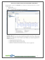
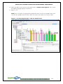
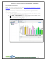
App/Platform Profiler
AppCOE enables you to view API performance data
The App/Platform Profiler feature enables API data collection
Collected data provides feedback concerning the utilization of MapuSoft‘s APIs in the
project
Reports allow for performance impact analysis by detailing API execution time
Offers area, bar, line, pie and scatter charts for data analysis
Generate API timing report and Timing comparison report
Platform API Profiling–System specific API profiling
Application Profiling–User specific API profiling
Platforms Supported for App/Platform Profiler
VxWorks 6x® and VxWorks 5x®
Linux 2.4® and Linux 2.6®
LynxOS® and LynxOS-SE®
Solaris
Unix®
Windows CE®
Windows XP ,Window 7 & Windows 8 ®
QNX®
For more information on Profiling, refer to App/Platform Profiler.
43
APPLICATION COMMON OPERATING ENVIRONMENT USER MANUAL
Chapter 4.Using OS Simulator
This chapter contains the following topics:
List of Available OS Simulators
Host Development Environment
Creating an AppCOE C/C++ Project
AppCOE C/C++ Project Template Files
Host System Configuration
Creating AppCOE C/C++ Project with Multiple Interfaces
Adding Source Code Files to AppCOE C/C++ Project
Building Your Project
Executing Binary Files
Debugging the Demos Supplied by MapuSoft
Debugging Using External Console/Terminal
Inserting Application Code to Run only on Host Environment
Updating Project Settings
44
APPLICATION COMMON OPERATING ENVIRONMENT USER MANUAL
List of Available OS Simulators
The following is the list of available OS Simulators:
VxWorks
pSOS
Nucleus
POSIX/LINUX/Linux
uITRON
Windows
ThreadX
Host Development Environment
Host development needs a proper environment to run and build embedded programs. To
develop an environment you need the following GNU tools:
Eclipse IDE
MinGW
GNU Compiler
PAL Debugger
Eclipse
An IDE is a powerful set of tools in the Application Common Operating Environment
(AppCOE) development suite. The IDE is based on the Eclipse Platform developed by
Eclipse.org, an open consortium of tools vendors.
The IDE incorporates into the Eclipse framework several AppCOE -specific plugins designed
for building projects for target systems running on HOST. The tools suite provides a single,
consistent, integrated environment; regardless of the host platform you are using Windows
or Linux. Plugins from most vendors should work within the Eclipse framework in the
same way.
NOTE: For more information on Eclipse and working on Eclipse framework, refer to
http://www.eclipse.org/documentation/.
MinGW
MinGW, a contraction of "Minimalist GNU for Windows", is a port of the GNU Compiler
Collection (GCC), and GNU Binutils, for use in the development of native Microsoft Windows
applications. Offered in easily installed binary package format, for native deployment on
MS-Windows, or user-built from source, for cross-hosted use on UNIX or GNU/Linux, the
suite exploits Microsoft's standard system DLLs to provide the C-Runtime and Windows
API. It is augmented by additional function libraries for improved ISO C-99 compatibility,
and further, by community supported add-on tools and libraries, many pre-built, many
more in the form of "mingw PORTs", to be built by the end user.
MinGW provides a complete Open Source programming tool set which is suitable for the
development of native MS-Windows applications, and which do not depend on any 3rdparty C-Runtime DLLs.
45
APPLICATION COMMON OPERATING ENVIRONMENT USER MANUAL
GNU Compiler
The GNU Compiler Collection includes front ends for C, C++, Java as well as libraries for
these languages (such as libstdc++, libgcj).
AppCOE Supplied GDB
A debugger is a computer program that is used to test and debug other programs (the
"target" program). The code to be examined might alternatively be running on an instruction
set simulator (ISS), a technique that allows great power in its ability to halt when specific
conditions are encountered but which will typically be somewhat slower than executing the
code directly on the appropriate processor. Some debuggers offer two modes of operation full or partial simulation to limit this impact.
Typically, debuggers also offer more sophisticated functions such as running a program
step by step (single-stepping or program animation), stopping (breaking) (pausing the
program to examine the current state) at some event or specified instruction by means of a
breakpoint, and tracking the values of some variables. Some debuggers have the ability to
modify the state of the program while it is running, rather than merely to observe it. It may
also be possible to continue execution at a different location in the program.
The GNU Debugger, usually called just GDB and named gdb as an executable file, is the
standard debugger for the GNU software system. It is a portable debugger that runs on
many Unix-like systems and works for many programming languages.
While working on AppCOE, you must use MapuSoft‘s GNU Debugger, called as ―AppCOE
Supplied GDB‖.
46
APPLICATION COMMON OPERATING ENVIRONMENT USER MANUAL
Creating an AppCOE C/C++ Project
NOTE: This feature requires a license. Click http://mapusoft.com/downloads/AppCOEevaluation/ to request an evaluation license.
To create an AppCOE C/C++ project:
1. From AppCOE main window, select any project under C/C++ Projects tab on the
left pane.
2. Select New > AppCOE C/C++ Project as shown in Figure 4_1.
Figure 4_1: Creating an AppCOE C Project
47
APPLICATION COMMON OPERATING ENVIRONMENT USER MANUAL
3. On AppCOE C/C++ Project Wizard window, type a project name and give a location
next to Project Name text box.
4. Under Project Types, expand the Executable menu. Select AppCOE Template
Project and click Next as shown in Figure 4_2.
Figure 4_2: AppCOE C Project Wizard Window
48
APPLICATION COMMON OPERATING ENVIRONMENT USER MANUAL
5. On Basic Settings window, define the basic properties of your project and click Next
as shown in Figure 4_3.
Figure 4_3: Basic Settings Window
49
APPLICATION COMMON OPERATING ENVIRONMENT USER MANUAL
6. On Select Configurations window, select the platforms and configurations for
deployment and click Next as shown in Figure 4_4.
Figure 4_4: Configurations Window
50
APPLICATION COMMON OPERATING ENVIRONMENT USER MANUAL
7. On Select APIs Interface window, select the required AppCOE development APIs
and click Finish as shown in Figure 4_5.
Figure 4_5: Select APIs Window
8. On Select Host Library Configuration window, select OS Abstractor Process Mode if
the created application runs in multiple process as shown in Figure 4_6.
51
APPLICATION COMMON OPERATING ENVIRONMENT USER MANUAL
Figure 4_6: Select Host Library Configuration Window
52
APPLICATION COMMON OPERATING ENVIRONMENT USER MANUAL
You can see the output as shown in Figure 4_7.
Figure 4_7: Creating AppCOE C/C++ Project Output
53
APPLICATION COMMON OPERATING ENVIRONMENT USER MANUAL
AppCOE C/C++ Project Template Files
To view the AppCOE C/C++ project template files, expand the project folder you have just
created by clicking on the +sign beside the Project name as shown in Figure 4_8.
Figure 4_8: AppCOE C/C++ Project Template Files
You can view the following template files for your project on the left pane of the window:
__os_init__linux_host.c–This function is the entry function for the native operating
system. This is where you should put any of your operating system specific code. For
instance, if you want to add a signal handler on Linux host, you could do it here before
calling OS_Main().
__os_init_linux.c–This function is the entry function for the native operating system. This
is where you should put any of your operating system specific code. For instance, if you
want to add a signal handler on Linux, you could do it here before calling OS_Main().
__os_init_lynxos.c– This function is the entry function for the native operating system.
This is where you should put any of your operating system specific code. For instance, if
you want to add a signal handler on Lynxos, you could do it here before calling
OS_Main().
__os_init_mqx.c–This function is the entry function for the native operating system. This
is where you should put any of your operating system specific code. For instance, if you
wanted to add a signal handler on MQX, you could do it here before calling OS_Main().
__os_init_nucleus.c– This function is the entry function for the native operating system.
This is where you should put any of your operating system specific code. For instance, if
you wanted to add a signal handler on Nucleus, you could do it here before calling
OS_Main().
54
APPLICATION COMMON OPERATING ENVIRONMENT USER MANUAL
__os_init_qnx.c– This function is the entry function for the native operating system. This
is where you should put any of your operating system specific code. For instance, if you
wanted to add a signal handler on QNX, you could do it here before calling OS_Main().
__os_init_solaris.c– This function is the entry function for the native operating system.
This is where you should put any of your operating system specific code. For instance, if
you want to add a signal handler on Solaris, you could do it here before calling
OS_Main().
__os_init_threadx.c– This function is the entry function for the native operating system.
This is where you should put any of your operating system specific code. For instance, if
you want to add a signal handler on ThreadX, you could do it here before calling
OS_Main ().
__os_init_uitron.c– This function is the entry function for the native operating system.
This is where you should put any of your operating system specific code. For instance, if
you want to add a signal handler on micro-ITRON, you could do it here before calling
OS_Main ().
__os_init_vxworks.c– This function is the entry function for the native operating system.
This is where you should put any of your operating system specific code. For instance, if
you want to add a signal handler on VxWorks, you could do it here before calling
OS_Main ().
__os_init_windows_host.c–These functions are the various entry functions for the
different operating systems. This is where you should put any of your operating system
specific code. For instance, if you want to add a signal handler on Windows host, you
could do it here before calling OS_Main ().When optimizing, you will need to write an
equivalent function for your target operating system.
__os_init_windows.c– These functions are the various entry functions for the different
operating systems. This is where you should put any of your operating system specific
code. For instance, if you want to add a signal handler on Windows, you could do it here
before calling OS_Main(). When optimizing, you will need to write an equivalent function
for your target operating system.
__os_init_android.c–This function is the entry function for the native operating system.
This is where you should put any of your operating system specific code. For instance, if
you want to add a signal handler on android, you could do it here before calling OS_Main
().
__os_init_ucos.c–This function is the entry function for the native operating system. This
is where you should put any of your operating system specific code. For instance, if you
want to add a signal handler on uCOS, you could do it here before calling OS_Main().
__os_init_netbsd.c–This function is the entry function for the native operating system.
This is where you should put any of your operating system specific code. For instance, if
you want to add a signal handler on NetBSD, you could do it here before calling OS_Main
().
os_application_start.c– This function is the first OS agnostic function and should be the
start point for the application development.
os_library_init.c– This function initializes the required Interface products and creates the
entry threads for each product.
os_main.c– This function initializes the
OS Abstractor Interface layer and calls
OS_Application_Wait_For_End which will suspend until OS_Application_Free or
OS_Delete_Process is called. It also spawns the first OS Independents thread which is the
true entry point for OS Abstractor Interface.
55
APPLICATION COMMON OPERATING ENVIRONMENT USER MANUAL
The application code starts in the os_library_init.c file, the user defined entry function and
name of the application for OS Abstractor Interface can be specified in:
#define OS_ABSTRACTOR_BASE_ENTRY_FUNCTION
#define OS_APPLICATION_START_TASK_NAME
For VxWorks Interface, the user defined entry function and stack size can be specified in:
#define VXWORKS_ENTRY_FUNCTION
#define VXWORKS_ENTRY_FUNCTION_STACK_SIZE
Similarly, this is how it works for all the remaining changers/abstractors.
You can insert code that is only included when they use AppCOE host in the following way:
For windows host you can insert code in __os_init_windows_host.c (inside main
function before calling OS_MAIN), that is only included in AppCOE windows host.
For Linux host, you can insert code in __os_init_linux_host.c (inside main function
before calling OS_MAIN), that is only included in AppCOE Linux host.
You can insert code that is specific to a target OS (inside main function before calling
OS_MAIN) in the following way:
For LynxOS target, insert in __os_init_lynxos.c
For mqx target, insert in __os_init_mqx.c
For Linux target, insert in __os_init_linux.c
For Nucleus target, insert in __os_init_nucleus.c
For QNX target, insert in __os_init_qnx.c
For Solaris target, insert in __os_init_solaris.c
For Threadx target, insert in __os_init_threadx.c
For uITRON target, insert in __os_init_uitron.c
For VxWorks target, insert in __os_init_vxworks.c
For Android target, insert in __os_init_android.c
For uCOS target, insert in __os_init_ucos.c
For NetBSD target, insert in __os_init_netbsd.c
56
APPLICATION COMMON OPERATING ENVIRONMENT USER MANUAL
Host System Configuration
The below defines are the system settings used by the OS_Application_Init() function. Use
these to modify the settings when running on the host. A value of -1 for any of these will
use the default values located in cross_os_usr.h. When you optimize for the target side
code, the wizard will create a custom cross_os_usr.h using the settings you specify at that
time so these defines will no longer be necessary.
#define
#define
#define
#define
#define
#define
#define
#define
#define
#define
#define
#define
#define
#define
#define
#define
#define
#define
#define
#define
HOST_DEBUG_INFO
HOST_TASK_POOL_TIMESLICE
HOST_TASK_POOL_TIMEOUT
HOST_ROOT_PROCESS_PREEMPT
HOST_ROOT_PROCESS_PRIORITY
HOST_ROOT_PROCESS_STACK_SIZE
HOST_ROOT_PROCESS_HEAP_SIZE
HOST_ROOT_PROCESS_AFFINITY
HOST_DEFAULT_TIMESLICE
HOST_MAX_TASKS
HOST_MAX_TIMERS
HOST_MAX_MUTEXES
HOST_MAX_PIPES
HOST_MAX_PROCESSES
HOST_MAX_QUEUES
HOST_MAX_PARTITION_MEM_POOLS
HOST_MAX_DYNAMIC_MEM_POOLS
HOST_MAX_EVENT_GROUPS
HOST_MAX_SEMAPHORES
HOST_USER_SHARED_REGION1_SIZE
-1
-1
-1
-1
-1
-1
-1
-1
-1
-1
-1
-1
-1
-1
-1
-1
-1
-1
-1
-1
OS_HOST: This flag is used only in AppCOE environment. It is not used in the target
environment.
Host mode defines can be modified in os_main.c file. For example, modify maximum tasks
under host environment in HOST_MAX_TASKS.
NOTE: You can manually change the values in the Optimized Target Code Generator
Wizard. Refer to Generating Optimized Target Code chapter in the manual.
57
APPLICATION COMMON OPERATING ENVIRONMENT USER MANUAL
Creating AppCOE C/C++ Project with Multiple Interfaces
NOTE: This feature requires a license. Click http://mapusoft.com/downloads/AppCOEevaluation/ to request an evaluation license.
To create AppCOE C/C++ project with multiple interfaces:
1. From AppCOE main window, select any project under C/C++ Projects tab on the
left pane.
2. Select New > AppCOE C/C++ Project as shown in Figure 4_9.
Figure 4_9: Creating a Project with Multiple Interfaces
58
APPLICATION COMMON OPERATING ENVIRONMENT USER MANUAL
3. On AppCOE C Project Wizard window, type a project name and give a location next
to Project Name text box.
4. Under Project Types, expand the Executable menu. Select AppCOE Template
Project and click Next as shown in Figure 4_10.
Figure 4_10: AppCOE C Project Wizard Window
59
APPLICATION COMMON OPERATING ENVIRONMENT USER MANUAL
5. On Basic Settings window, define the basic properties of your project and click Next
as shown in Figure 4_11.
Figure 4_11: Basic Settings Window
60
APPLICATION COMMON OPERATING ENVIRONMENT USER MANUAL
6. On Select Configurations window, select the platforms and configurations for
deployment and click Next as shown in Figure 4_12.
Figure 4_12: Configurations Window
61
APPLICATION COMMON OPERATING ENVIRONMENT USER MANUAL
7. On Select APIs window, select the required check box. In this example, we have
shown Nucleus and VxWorks Interfaces API’s, selected. click Finish as shown in
Figure 4_13.
Figure 4_13: Select APIs Window.
8. On Select Host Library Configuration window, select OS Abstractor Process Mode if
the created application runs in multiple processes as shown in Figure 4_14.
62
APPLICATION COMMON OPERATING ENVIRONMENT USER MANUAL
Figure 4_14: Select Host Library Configuration Window .
63
APPLICATION COMMON OPERATING ENVIRONMENT USER MANUAL
You can see the output as shown in Figure 4_15.
Figure 4_15: A Project with multiple Interfaces Output
64
APPLICATION COMMON OPERATING ENVIRONMENT USER MANUAL
Adding Source Code Files to AppCOE C/C++ Project
NOTE: This feature requires a license. Click http://mapusoft.com/downloads/AppCOEevaluation/ to request an evaluation license.
To add source code files:
1. Select a project under C/C++ Projects pane.
2. Right click on it and select Import as shown in Figure 4_16.
Figure 4_16: Adding Source Code Files
65
APPLICATION COMMON OPERATING ENVIRONMENT USER MANUAL
3. Select your import source and click Next as shown in Figure 4_17.
Figure 4_17: Importing Files from Local File System
66
APPLICATION COMMON OPERATING ENVIRONMENT USER MANUAL
4. Select the directory on your local file system which contains the source code files
and click OK as shown in Figure 4_18.
Figure 4_18: Importing Source Code Files from Directory
5. Select the check boxes corresponding to the source code files you want to import
and click Finish as shown in Figure 4_19.
Figure 4_19: Selecting Source Code Files for Importing
67
APPLICATION COMMON OPERATING ENVIRONMENT USER MANUAL
6. You can view the source code files added to your AppCOE C/C++ project as shown
in Figure 4_20.
Figure 4_20: Importing Source Code Files Output
68
APPLICATION COMMON OPERATING ENVIRONMENT USER MANUAL
Building Your Project
NOTE: This feature requires a license. Click http://mapusoft.com/downloads/AppCOEevaluation/ to request an evaluation license.
1. Creating an AppCOE C/C++ Project.
2. Adding Source Code Files to AppCOE C/C++ Project.
3. Select a project under C/C++ Projects pane, right click and select Build Project as
shown in Figure 4_21.
Figure 4_21: Building Your Project
69
APPLICATION COMMON OPERATING ENVIRONMENT USER MANUAL
4. You can view how the binary files are built in Figure 4_22.
Figure 4_22: Output for Building Binary Files for a Project
70
APPLICATION COMMON OPERATING ENVIRONMENT USER MANUAL
Executing Binary Files
To execute the binary in Windows host:
1. Select Project that you have created.
2. Select the Binary file, right click and select Open With > System Editor as shown
in Figure 4_23.
Figure 4_23: Executing the Binary File
71
APPLICATION COMMON OPERATING ENVIRONMENT USER MANUAL
3. This approach always will fork a terminal to view the output as shown in Figure
4_24.
Figure 4_24: Binary Output
72
APPLICATION COMMON OPERATING ENVIRONMENT USER MANUAL
Debugging the Demos Supplied by MapuSoft
Example: Debugging the demo_cross_os application
1. From AppCOE main window, select demo_cross_os project.
2. Right click on the project and select Debug as > Local AppCOE C\C ++ Application
or click on debugging icon as highlighted in Figure 4_25.
Figure 4_25: Debugging the Demo Application
NOTE: If the user uses the Debug dialog to create a new configuration then they need to
select AppCOE Local C/C++ Application before creating. The other option is to not use the
debug dialog, but instead select ―AppCOE Local C/C++ Application" from the Debug As
menu. This method will create the correct configuration automatically.
3. After selected the AppCOE Local Application for debugging, Confirm Perspective
Switch window is to confirm the
Debug Perspective support for debugging the
application and it is displayed as shown in Figure 4_26, at a same time, windows
command prompt is displayed as shown in Figure 4_27.
Note: if the user used to open the Debug Perspective for debugging the application
by click Yes button, then debugging progress is started as shown in Figure 4_28.
73
APPLICATION COMMON OPERATING ENVIRONMENT USER MANUAL
Figure 4_26: Confirm Perspective Switch window
Figure 4_27: Confirm Perspective Switch window & Windows Command Prompt
opened
74
APPLICATION COMMON OPERATING ENVIRONMENT USER MANUAL
Figure 4_28: Debugging Progress Information
.
4. Debugging stops at the main function. Click Resume icon (highlighted in red circle)
to resume the debugging process as shown in Figure 4_29.
Figure 4_29: Resume Debugging process
5. The debugging resumes as shown in Figure 4_30.
75
APPLICATION COMMON OPERATING ENVIRONMENT USER MANUAL
Figure 4_30: Debug Demo Application Perspective
You can see the debugging on the console as shown in Figure 4_31.
Figure 4_31: Debug Demo Application Output
Note: If the user not use the Debug Perspective by click No button from Debug
Perspective windows as shown in a Figure 4_26. Debugging the Demo application
from AppCOE only as shown in the Figure 4_32 and Figure 4_33.
Note: Best ways is user should use the Debug Perspective for debugging the demo
application, because its only helps to views for displaying the debug stack, variables,
breakpoint management.
76
APPLICATION COMMON OPERATING ENVIRONMENT USER MANUAL
Figure 4_32: Debug Demo Application Using AppCOE
Figure 4_33: Resume Debugging process
77
APPLICATION COMMON OPERATING ENVIRONMENT USER MANUAL
Debugging Using External Console/Terminal
Debugging can be done using an external console or terminal in the following way:
1. From AppCOE main window, select the demo_cross_os project.
2. Right click on the project and select Debug as > Debug Configuration as shown in
Figure 4_34.
Figure 4_34: Open Debug Dialog
78
APPLICATION COMMON OPERATING ENVIRONMENT USER MANUAL
3. On Debug Configuration window, you can set your options for debugging as shown
in the Figure 4_35,
NOTE: You must use MapuSoft Supplied GDB to execute debugging.
NOTE: AppCOE does not support Cygwin tools and its use is not recommended.
Figure 4_35: Debug Configuration Window
4. You can change any of the options here and click Apply.
79
APPLICATION COMMON OPERATING ENVIRONMENT USER MANUAL
5. Click Debug to execute debugging using the external console or Terminal. You can
view the debugging process in your console as shown in Figure 4_36.
Figure 4_36: Debugging Output Using External Console/Terminal
80
APPLICATION COMMON OPERATING ENVIRONMENT USER MANUAL
6. To resume debugging, click the resume icon
in the Figure 4_37.
on the debugging window as shown
Figure 4_37: Resume Debugging Using External Console/Terminal
81
APPLICATION COMMON OPERATING ENVIRONMENT USER MANUAL
7. You have now successfully finished debugging by using external console or terminal
as shown in Figure 4_38.
Figure 4_38: Debugging in Progress
82
APPLICATION COMMON OPERATING ENVIRONMENT USER MANUAL
Inserting Application Code to Run only on Host Environment
The below defines are the system settings used by the OS_Application_Init() function. Use
these to modify the settings when running on the host. A value of -1 for any of these will
use the default values located in cross_os_usr.h.
When you optimize for the target side code, the wizard will create a custom cross_os_usr.h
using the settings you specify at that time so these defines will no longer be necessary.
You can add some application code or debug statements like printf, assert, which is mostly
used in host environment only. This line of code will be ignored by the compiler in target
environment.
OS HOST Selection
The flag has to be false for Full Source Library Package generation.
Table 4_1: OS HOST Selection
Flag and Purpose
Available Options
OS_HOST
To select the host operating
system
This flag is set as OS_TRUE by default in
AppCOE environment.
Target 64 bit CPU Selection
Based on the OS you want the application to be built, set the following pre-processor
definition in your project setting or make files:
Table 4_2: Target 64 bit CPU Selection
Flag and Purpose
OS_CPU_64BIT
To select the target CPU
type.
Available Options
The value of OS_CPU_64BIT can be any ONE of
the following:
OS_TRUE – Target CPU is 64 bit type CPU
OS_FALSE – Target CPU is 32 bit type CPU
NOTE: In New C projects creation, the flag
OS_CPU_64BIT will be set to OS_FALSE by
default and user needs to make this true if they
run on a 64-bit OS.
83
APPLICATION COMMON OPERATING ENVIRONMENT USER MANUAL
Updating Project Settings
AppCOE provides exclusive way to update the Projects Settings by just a click of a button.
This is very useful in any one of the following cases:
1. If the user has moved his workspace to a different location
2. If the project requires new tool-chain that is installed recently
The Update button performs an auto update on all the projects updates which include files,
new directory structures, libraries, and tool-chains to the Project Settings.
To update project settings:
1. From AppCOE main menu select Tools > Update Settings or click AppCOE C/C++
Project Settings button
on AppCOE main menu or, as shown in Figure 4_39.
Figure 4_39: Updating Project Settings
84
APPLICATION COMMON OPERATING ENVIRONMENT USER MANUAL
2. AppCOE does an auto search for the project updates and updates the settings as
shown in the Project Settings Updating window in Figure 4_40.
Figure 4_40: AppCOE C/C++ Project Updates
85
APPLICATION COMMON OPERATING ENVIRONMENT USER MANUAL
Chapter 5. Using OS Changer Porting Kit
This chapter contains the following topics:
About OS Changer Interfaces Available for OS Changer
Using OS Changer
Error Handling
Porting VxWorks Applications
Porting a WindRiver Workbench ‗C‘ Project
Porting VxWorks Legacy ‗C‘ Code
Manually Porting Legacy Applications using Import Feature
Porting POSIX/LINUX Legacy ‗C‘ Code
Porting Applications from Nucleus PLUS Legacy Code to Target OS
Porting Nucleus Legacy ‗C‘ Code
Porting Threadx Legacy ‗C‘ Code Porting pSOS Legacy ‗C‘ Code
Porting micro-ITRON Legacy ‗C‘ Code
Porting Windows Legacy ‗C‘ Code
Building OS Abstractor Interface Library
OS Changer VxWorks Interface
OS Changer POSIX/LINUX Interface
OS Changer Nucleus Interface
OS Changer ThreadX Interface
OS Changer pSOS Interface
OS Changer micro-ITRON Interface
OS Changer Windows Interface
Building Application with Multiple Interface Components
86
APPLICATION COMMON OPERATING ENVIRONMENT USER MANUAL
About OS Changer
OS Changer allows you to reuse the code on any new OS without having to rewrite or port
your code. This saves time and money by reducing the porting effort.
OS Changer provides extensive support to various common proprietary libraries widely used
by the application developers. Further, developers can use the native TARGET OS interface
as well. This works toward getting the migration effort faster and much easier.
Figure 5_1: About OS Changer
OS Changer is designed for use as a C library. Services used inside your application
software are extracted from the OS Changer and TARGET OS libraries, and, are then
combined with the other application objects to produce the complete image.
OS Changer is optimized to take full advantage of the underlying TARGET RTOS features. It
is built to be totally independent of the target hardware and all the development tools (like
compilers and debuggers).
Please note that there may be some minor implementation differences in some of the OS
Changer APIs when compared to the native API‘s. This may be as a result of any missing
features within the underlying RTOS that OS Changer provides migration to.
87
APPLICATION COMMON OPERATING ENVIRONMENT USER MANUAL
Figure 5_2: OS Changer Flow Diagram
Your legacy application can be re-usable and also portable by the support provided by the
OS Changer library and the OS Abstractor library. Applications can directly use the native
target OS API, however doing so will not make your code portable across operating systems.
We recommend that you use the optimized abstraction APIs for the features and support
that are not provided by the OS Changer compatibility library.
NOTE: For more information on configuration and target OS specific information, see OS
Abstractor Interface Reference Manual.
Interfaces Available for OS Changer
The following are the interfaces available for OS Changer:
VxWorks
Nucleus
pSOS
micro-ITRON
POSIX/LINUX
Windows
ThreadX
88
APPLICATION COMMON OPERATING ENVIRONMENT USER MANUAL
Using OS Changer
OS Changer is designed for use as a C library. Services used inside your application
software are extracted from the OS Changer and TARGET OS libraries, and, are then
combined with the other application objects to produce the complete image. This image can
be loaded to the target system or placed in ROM on the target system.
The steps for using OS Changer are described in the following generic form:
Remove the TARGET RTOS header file defines from all the TARGET RTOS
source files.
Remove definitions and references to all the TARGET RTOS configuration data
structures in your application.
Include the TARGET RTOS_interface.h (For example, nucleus_interface.h in
case of OS Changer Nucleus Interface) and os_target.h in the source files.
Modify the OS Changer init code (see sample provided) and the TARGET RTOS
root task of your application appropriately. (For example, Application_Initialize)
Compile and link your application using appropriate development tools. Resolve
all compiler and linker errors.
Port the underlying low-level drivers to Target OS.
Load the complete application image to the target system and run the
application.
Review the processor and development system documentation for additional
information, including specific details on how to use the compiler, assembler,
and linker.
Error Handling
Applications receive a run-time error via the OS_Fatal_Error () function on some occasions.
This happens due to:
Unsupported API function call, or
Unsupported parameter value or flag option in a API call, or
Error occurred on the target OS for which there are no matching error codes in
OS Abstractor Interface.
OS Changer calls OS_Fatal_Error and passes along an error code and error string. The
OS_Fatal_Error handling function is fully customizable to the application needs. At the
moment it prints the error message if the OS_DEBUG_INFO conditional compile option is
set, then OS_Fatal_Error does not return. For more details on error handling and definition
of this function, refer to the OS Abstractor Interface Reference Guide. The non-zero value in
the error code corresponds to the underlying RTOS API error. Refer to the target OS
documentation for a better description of the errors. Error Handling section lists the errors
and the reasons for the occurrence.
89
APPLICATION COMMON OPERATING ENVIRONMENT USER MANUAL
Porting VxWorks Applications
Porting applications into the AppCOE host environment can be done in three different ways:
1. Porting a WindRiver Workbench project
2. Porting a Legacy application
3. Manual porting using AppCOE
Method 1– Porting a WindRiver Workbench ‘C’ Project
NOTE: This feature requires a license. Click http://mapusoft.com/downloads/AppCOEevaluation/ to request an evaluation license.
1. From AppCOE main window, select any project under C/C++ Projects tab on the
left pane.
2. Select Tools > Porting >VxWorks> Import Workbench ‘C’ Project as shown in
Figure 5_3. You can also click on the Porting icon
from the task bar.
Figure 5_3: Importing a VxWorks Workbench ‘C’ Project in AppCOE
90
APPLICATION COMMON OPERATING ENVIRONMENT USER MANUAL
3. On AppCOE Import window, select a workspace directory to search for existing
workbench projects by clicking on Browse button next to the text box, and click
Next as shown in Figure 5_4.
4. On Select Host Library Configuration window, select OS Abstractor Process Mode if
the imported application runs in multiple process
5. In Import Wind River Workbench Projects window, the projects list is displayed in a
checkbox Tree. Application projects and Library projects are separated into
respective categories.
6. Select or deselect any one or all of the projects by selecting the check box next to the
project name and click Finish to import the project as shown in Figure 5_4.
Figure 5_4: AppCOE Import Window
91
APPLICATION COMMON OPERATING ENVIRONMENT USER MANUAL
The following are the project types:
Application Projects - Provides an executable application. This project type folder
contains three templates. The makefile for the Executable project type is
automatically created by the CDT.
Library Projects- An executable module that is compiled and linked separately.
When you create a project that uses a shared library (libxx.so), you define your
shared library's project as a Project Reference for your application. The makefile for
this project type is automatically created by the CDT.
NOTE: Select the check box next to your required library or application project to be
imported.
7. If you select Application project, and click Finish, you get Application Start up Files
window as shown in Figure 5_5.
Figure 5_5: Application Startup Files Window
8. If you are importing a kernel application, click Yes to automatically create start up
files to connect the imported application to the OS platform.
NOTE: If you are porting a library project, click No to continue with the porting.
9. If you select any application type project, provide the inputs for the project and click
OK as shown in Figure 5_6. If you do not want to provide the inputs, you can just
click Cancel.
92
APPLICATION COMMON OPERATING ENVIRONMENT USER MANUAL
Figure 5_6: Provide Inputs for Projects Window
NOTE: If you select an application project and if it contains any referenced projects
not selected by you, then a Confirmation dialogue box is displayed on your screen to
ask if you want to port the project. If you want to port, click OK. You can see the
porting processing results as shown in Figure 5_6 .
After the porting is successfully done, the porting report page is displayed as shown
in Figure 5_7, Click Done to complete the process.
Figure 5_7: Porting Reports Page
93
APPLICATION COMMON OPERATING ENVIRONMENT USER MANUAL
10. In order to successfully compile your application, follow the guidelines highlighted
as shown in Figure 5_8 .
Figure 5_8: Porting Reports Page Guidelines
94
APPLICATION COMMON OPERATING ENVIRONMENT USER MANUAL
11. In AppCOE C/C++ projects perspective, the ported projects are displayed as
shown in Figure 5_9.
Figure 5_9: Project Perspective of the Ported Projects
You have successfully imported your VxWorks application to AppCOE.
To know more about the project template files, go to AppCOE C/C++Project Template Files.
95
APPLICATION COMMON OPERATING ENVIRONMENT USER MANUAL
Method 2–Porting VxWorks Legacy ‘C’ Code
This section explains Porting VxWorks Legacy Applications using AppCOE Porting Plug-in.
A sample porting of VxWorks Legacy application using AppCOE is described with an
example here.
NOTE: This feature requires a license. Click http://mapusoft.com/downloads/AppCOEevaluation/ to request an evaluation license.
1. Select Tools> Porting >VxWorks> Import Legacy ‘C’ Code as shown in Figure
5_10. You can also click on the Porting icon
from the task bar.
Figure 5_10: Importing VxWorks Legacy ‘C’ Code in AppCOE
96
APPLICATION COMMON OPERATING ENVIRONMENT USER MANUAL
3. On AppCOE Import Window select the Import Application Project/Library Project
radio button with reference to your project. Here we are considering importing a
application project for example purpose.
4. Select the root directory from where you want to import the legacy code by clicking
on Browse button next to the text box, and click Next as shown in Figure 5_11.
5. On Select Host Library Configuration window, select OS Abstractor Process Mode if
the imported application runs in multiple process.
Figure 5_11: Import Legacy Code Window
6. Enter the project name for which you want to import the legacy code in the Project
Name text box.
7. Enter the root task prototype as (int usrROOT(UNSIGNED argc), next to Root Task
Prototype text box.
8. Enter the root task stack size, next to the Root Task Stack Size text box. The value
should be in bytes.
9. Click Finish to complete the importing of legacy code into AppCOE.
10. You have successfully imported the legacy code and a project with your given project
name is created in the current workspace.
97
APPLICATION COMMON OPERATING ENVIRONMENT USER MANUAL
Method 3– Manually Porting Legacy Applications using Import Feature
Step 1: In your source code, remove references to the original OS include files and
use os_target.h and the header files of your ported legacy API instead.
1. Remove the original OS specific initialization code and use OS_Application_Init
function call instead (refer to the OS Abstractor Interface Reference Manual).
2. Create an AppCOE C/C++ project for your legacy application and select the
legacy API that your application will need (E.g.: to port VxWorks application, you
need to check the ―Include OS Changer VxWorks Interface API‘s‖).
3. If your application uses any APIs that are not supported under AppCOE, re-write
the code using OS Abstractor Interface APIs.
4. Import your legacy application into the new project.
5. Compile and link your application and resolve all compiler and linker errors.
6. Run or debug your application under AppCOE host in an x86 environment. You
should rewrite/replace any hardware specific code in your application for this
step.
Step 2: Moving from AppCOE Host to target using AppCOE Optimized Target Code
Generator:
1)
Generate the code for your target OS using the AppCOE Optimized Target
Code Generator.
2) Using cross-compiler compile, link, and download the AppCOE generated
code to your target.
3) Port low level drivers and hardware interrupt code as required (refer to
OS Abstractor Interface I/O and device driver APIs sections in the OS
Abstractor Reference Manual).
4) Resolve any run time errors.
98
APPLICATION COMMON OPERATING ENVIRONMENT USER MANUAL
Porting POSIX/LINUX Legacy ‘C’ Code
This section explains Porting POSIX/LINUX Legacy Applications using AppCOE Porting
Plugin. A sample porting of POSIX/LINUX Legacy applications using AppCOE is described
with an example here.
NOTE: This feature requires a license. Click http://mapusoft.com/downloads/AppCOEevaluation/ to request an evaluation license.
To port a sample POSIX/LINUX legacy application:
1. Select Tools> Porting >POSIX/LINUX> Import Legacy ‘C’ Code as shown in
Figure 5_12. You can also click on the Porting icon
from the task bar.
Figure 5_12: Porting POSIX/LINUX Legacy ‘C’ Code in AppCOE
99
APPLICATION COMMON OPERATING ENVIRONMENT USER MANUAL
3. On AppCOE Import Window select the Import Application Project/Library Project
radio button with reference to your project. Here we are considering importing a
application project for example purpose.
4. Select the root directory from where you want to import the legacy code by clicking
on Browse button next to the text box, and click Next as shown in Figure 5_13.
Figure 5_13: Import POSIX/LINUX Legacy Code Window
5. Enter the project name for which you want to import the legacy code in the Project
Name text box.
6. Enter the root task prototype as int px_main(int argc, char* argv[]), next to Root
Task Prototype text box.
7. Enter the root task stack size, next to the Root Task Stack Size text box. The value
should be in bytes.
100
APPLICATION COMMON OPERATING ENVIRONMENT USER MANUAL
8. Click Finish to complete the importing of legacy code into AppCOE. You can see
POSIX/LINUX legacy code you have imported as shown in Figure 5_14.
Figure 5_14 : Importing POSIX/LINUX Legacy Code Output
You have successfully imported the POSIX/LINUX legacy C code and a project with
your given project name is created in the current workspace.
101
APPLICATION COMMON OPERATING ENVIRONMENT USER MANUAL
Porting Applications from Nucleus PLUS Legacy Code to Target OS
In most applications, using Nucleus OS Changer is straightforward. The effort required in
porting is mostly at the underlying driver layer. Since we do not have specific information
about your application, it will be hard to tell how much work is required. However, we
want you to be fully aware of the surrounding issues upfront so that necessary steps could
be taken for a successful and timely porting. This section provides porting guidelines in a
flow chart format. This covers issues relating with Nucleus OS Changer, device drivers,
interrupt service routines, etc. It is possible that we have not addressed all your
application specific issues in the flow chart, so for further information, contact MapuSoft
Technologies.
Figure 5_15: Porting Nucleus PLUS Applications
Porting Nucleus PLUS Applications to Linux - Guidelines
Chart A - Kernel APIs, interrupts and device drivers
START
CHECK 1
Does your application uses kernel APIs' that
are un-supported in
Nucleus PLUS OS Changer?
Yes
Implement the
unsupported APIs
using
OS Abstractor or
target OS APIs
Yes
Modify your
application to
handle the
differences
No
CHECK 2
Does your application uses kernel APIs' that
are partially supported by
Nucleus PLUS OS Changer?
No
CHECK 3
Does your application configure the target
hardware differently than default setup in
Nucleus PLUS?
Yes
Modify the target OS
BSPs to the desired
target configuration
Yes
Port the device driver
routines to target OS or
modify application to use
target OS drivers instead
Yes
Make changes if needed to
make them to work under
target OS
No
CHECK 4
Are you using Nucleus PLUS based
device drivers?
No
CHECK 5
Are you using interrupt service routines that
are not part of the Nucleus PLUS based
device drivers?
No
Happy Porting
102
APPLICATION COMMON OPERATING ENVIRONMENT USER MANUAL
Porting Nucleus Legacy ‘C’ Code
This section explains Porting Nucleus Legacy Applications using AppCOE Porting Plugin. A
sample porting of Nucleus Legacy application using AppCOE is described with an example
here.
NOTE: This feature requires a license. Click http://mapusoft.com/downloads/AppCOEevaluation/ to request an evaluation license.
1. Select Tools> Porting > Nucleus > Import Legacy ‘C’ Code as shown in Figure
5_16 . You can also click on the Porting icon
from the task bar.
Figure 5_16 : Importing Nucleus Legacy ‘C’ Code in AppCOE
103
APPLICATION COMMON OPERATING ENVIRONMENT USER MANUAL
2. On AppCOE Import Window select the Import Application Project/Library Project
radio button with reference to your project. Here we are considering importing a
application project for example purpose.
3. Select the root directory from where you want to import the legacy code by clicking
on Browse button next to the text box, and click Next as shown in Figure 5_17.
4. On Select Host Library Configuration window, select OS Abstractor Process Mode
if the imported application runs in multiple process
Figure 5_17: Import Nucleus Legacy Code Window
5. Enter the project name for which you want to import the legacy code in the Project
Name text box.
6. Enter the root task prototype as VOID NucleusRoot(UNSIGNED argv,VOID*
argc);, next to Root Task Prototype text box.
7. Enter the root task stack size, next to the Root Task Stack Size text box. The value
should be in bytes.
8. Enter the root task name, next to Root Task Name text box.
104
APPLICATION COMMON OPERATING ENVIRONMENT USER MANUAL
9. Click Finish to complete the importing of legacy code into AppCOE. You can see the
output as shown in Figure 5_18.
Figure 5_18: Importing Nucleus Code Output
10. You have successfully imported Nucleus legacy C code and a project with your
given project name is created in the current workspace.
105
APPLICATION COMMON OPERATING ENVIRONMENT USER MANUAL
Porting Threadx Legacy ‘C’ Code
This section explains Porting Threadx Legacy Applications using AppCOE Porting Plugin. A
sample porting of Threadx Legacy application using AppCOE is described with an example
here.
NOTE: This feature requires a license. Click http://mapusoft.com/downloads/AppCOEevaluation/ to request an evaluation license.
1. Select
Tools > Porting > ThreadX > Import Legacy ‘C’ Code as shown in Figure
5_19. You can also click on the Porting icon
from the task bar.
Figure 5_19: Importing ThreadX Legacy ‘C’ Code in AppCOE
106
APPLICATION COMMON OPERATING ENVIRONMENT USER MANUAL
2. On AppCOE Import Window select the Import Application Project/Library Project
radio button with reference to your project. Here we are considering importing a
application project for example purpose.
3. Select the root directory from where you want to import the legacy code by clicking
on Browse button next to the text box, and click Next as shown in Figure 5_20.
4. On Select Host Library Configuration window, select OS Abstractor Process Mode if
the imported application runs in multiple process
Figure 5_20: Import Threadx Legacy Code Window
5. Enter the project name for which you want to import the legacy code in the Project
Name text box.
6. Enter the root task as a tx_kernel_enter(); prototype, next to Root Task
Prototype text box.
7. Enter the root task stack size, next to the Root Task Stack Size text box. The value
should be in bytes.
8. Enter the root task name, next to Root Task Name text box.
107
APPLICATION COMMON OPERATING ENVIRONMENT USER MANUAL
9. Click Finish to complete the importing of legacy code into AppCOE. You can see the
output as shown in Figure 5_21.
Figure 5_21: Importing Threadx Code Output
10. You have successfully imported ThreadX legacy C code and a project with your given
project name is created in the current workspace.
108
APPLICATION COMMON OPERATING ENVIRONMENT USER MANUAL
Porting pSOS Legacy ‘C’ Code
This section describes the sample porting of pSOS Legacy Applications using AppCOE
Porting Plug-in. A description for porting pSOS Legacy applications using AppCOE is
described with an example here.
NOTE: This feature requires a license. Click http://mapusoft.com/downloads/AppCOEevaluation/ to request an evaluation license.
1. Select Tools> Porting >pSOS> Import Legacy ‘C’ Code as shown in Figure 5_22,
you can also click on the Porting icon
from the task bar.
Figure 5_22: Importing pSOS Legacy ‘C’ Code in AppCOE
109
APPLICATION COMMON OPERATING ENVIRONMENT USER MANUAL
3. On AppCOE Import Window select the Import Application Project/Library Project
radio button with reference to your project. Here we are considering importing a
application project for example purpose.
4. Select the root directory from where you want to import the legacy code by clicking
on Browse button next to the text box, and click Next as shown Figure 5_23.
5. On Select Host Library Configuration window, select OS Abstractor Process Mode if
the imported application runs in multiple process
Figure 5_23: Import pSOS Legacy Code Window
6. Enter the project name for which you want to import the legacy code in the Project
Name text box as shown in the figure.
7. Enter the root task prototype as VOID Function_Root(ULONG argument);, next
to Root Task Prototype text box as shown in the Figure 5_24.
8. Enter the root task stack size, next to the Root Task Stack Size text box as shown
in Figure 5_24.. The value should be in bytes.
110
APPLICATION COMMON OPERATING ENVIRONMENT USER MANUAL
9. Click Finish to complete the importing of legacy code into AppCOE. You can see
POSIX/LINUX legacy code you have imported as shown in Figure 5_24 .
Figure 5_24: Importing pSOS Legacy Code Output
10. You have successfully imported pSOS legacy C code and a project with your given
project name is created in the current workspace.
111
APPLICATION COMMON OPERATING ENVIRONMENT USER MANUAL
Porting micro-ITRON Legacy ‘C’ Code
This section explains porting of micro-ITRON Legacy Applications using AppCOE Porting
Plugin. A sample porting of micro-ITRON Legacy applications using AppCOE is described
with an example here.
NOTE: This feature requires a license. Click http://mapusoft.com/downloads/AppCOEevaluation/ to request an evaluation license.
1. Select Tools > Porting >micro-ITRON> Import Legacy ‘C’ Code as shown in Figure
5_25. You can also click on the Porting icon
from the task bar.
Figure 5_25: Importing micro-ITRON Legacy ‘C’ Code in AppCOE
112
APPLICATION COMMON OPERATING ENVIRONMENT USER MANUAL
3. On AppCOE Import Window select the Import Application Project/Library Project
radio button with reference to your project. Here we are considering importing a
application project for example purpose.
4. Select the root directory from where you want to import the legacy code by clicking
on Browse button next to the text box, and click Next as shown in Figure 5_26.
5. On Select Host Library Configuration window, select OS Abstractor Process Mode if
the imported application runs in multiple process
Figure 5_26: Import micro-ITRON Legacy Code Window
6. Enter the project name for which you want to import the legacy code in the Project
Name text box.
7. Enter the root task prototype as a VOID uITRONRoot(UNSIGNED argv);, next to
Root Task Prototype text box as shown in Figure 5_27.
8. Enter the root task stack size, next to the Root Task Stack Size text box as shown.
The value should be in bytes.
113
APPLICATION COMMON OPERATING ENVIRONMENT USER MANUAL
9. Click Finish to complete the importing of legacy code into AppCOE . You can see
micro-ITRON legacy code you have imported as shown in Figure 5_27.
Figure 5_27: Importing micro-ITRON Legacy Code Output
10. You have successfully imported micro-ITRON legacy C code and a project with your
given project name is created in the current workspace.
114
APPLICATION COMMON OPERATING ENVIRONMENT USER MANUAL
Porting Windows Legacy ‘C’ Code
This section explains porting of Windows Legacy Applications using AppCOE Porting Plugin. A sample porting of Windows Legacy applications using AppCOE is described with an
example here.
NOTE: This feature requires a license. Click http://mapusoft.com/downloads/AppCOEevaluation/ to request an evaluation license.
1. Select Tools> Porting >Windows> Import Legacy ‘C’ Code as shown in Figure
5_28. You can also click on the Porting icon
from the task bar.
Figure 5_28: Importing Windows Legacy ‘C’ Code in AppCOE
115
APPLICATION COMMON OPERATING ENVIRONMENT USER MANUAL
3. On AppCOE Import Window select the Import Application Project/Library Project
radio button with reference to your project. Here we are considering importing a
application project for example purpose.
4. Select the root directory from where you want to import the legacy code by clicking
on Browse button next to the text box, and click Next as shown in Figure 5_29 .
5. On Select Host Library Configuration window, select OS Abstractor Process Mode if
the imported application runs in multiple process
Figure 5_29 : Import Windows Legacy Code
6. Enter the project name for which you want to import the legacy code in the Project
Name text box as shown in the Figure 5_29.
7. Enter the root task prototype like int win_main(int argc); next to Root Task
Prototype text box as shown in the Figure 5_29.
8. Enter the root task stack size, next to the Root Task Stack Size text box as shown
in the Figure 5_29. The value should be in bytes.
116
APPLICATION COMMON OPERATING ENVIRONMENT USER MANUAL
9. Click Finish to complete the importing of legacy code into AppCOE. You can see
Windows legacy C code you have imported as shown in Figure 5_30.
Figure 5_30: Importing Windows Legacy Code Output
You have successfully imported Windows legacy code and a project with your
given project name is created in the current workspace.
117
APPLICATION COMMON OPERATING ENVIRONMENT USER MANUAL
Building OS Abstractor Interface Library
Before using OS Abstractor Interface, make sure the OS and tools are configured correctly
for your target. To ensure this, compile, link and execute a native sample demo application
that is provided by the OS vendor on your target. Refer to the OS vendor provided
documentation on how to compile, link, download, and debug the demo applications for
your specific target and toolset. After this step, you are ready to use the OS Abstractor
Interface library to develop your applications.
Building OS Abstractor Interface Demo Application
The demo application is located at the \mapusoft\demo_cross_os directory location. From
this location, you will find the make files or project files at the appropriate
specific/<OS>/<tool>/<target> directory. For instance, if you need the demo application to
be built for Windows OS using visual studio 12 tools and for x86 target, then the make file
location will be at specific\windows\x86\vsnet2012 directory.
OS Changer VxWorks Interface
The OS Changer Nucleus Interface library contains the following modules
Table 5_1: VxWorks Interface Header File
Module
Description
vxworks_interface.h
This header file is required in all of the VxWorks
source modules. This header file provides the
translation layer between the VxWorks defines, APIs
and parameters to OS Abstraction
The OS Changer VxWorks Interface OS Changer OS Changer VxWorks Interface demo
contains the following modules:
Table 5_2: VxWorks Interface Demo Application File
Module
Description
demo.c
Contains a sample demo application
Building OS Changer VxWorks Interface
Before building the VxWorks Interface library and/or application, ensure that the flag
INCLUDE_OS_VxWorks is set to OS_TRUE in the cross_os_usr.h configuration file.
Building OS Changer VxWorks Interface Library
The VxWorksInterface library is located at \mapusoft\ vxworks_interface directory. From
this location, you will find the make files or project files at the appropriate
specific/<OS>/<tool>/<target> directory. For instance, if you need the demo application to
be built for VxWorks OS using Eclipse tools and for x86 targets, then the make file location
will be at specific\vxworks\<OS>\x86\eclipse directory.
Building OS Changer VxWorks Interface Demo Application
The demo application is located at the \mapusoft\ demo_vxworks directory location. From
this location, you will find the make files or project files at the appropriate
specific/<OS>/<tools>/<target> directory. For instance, if you need the demo application
to be built for VxWorks OS using Eclipse tools and for x86 targets, then the make file
location will be at specific\vxworks_interface\<OS>\x86\eclipse directory.
OS Changer POSIX/LINUX Interface
The OS Changer POSIX/LINUX Interface library contains the following modules:
118
APPLICATION COMMON OPERATING ENVIRONMENT USER MANUAL
Table 5_3: Posix Interface Header File
Module
Description
posix_interface.h
This header file is required in all of the POSIX/LINUX
source modules. This header file provides the
translation layer between the POSIX/LINUX defines,
APIs and parameters to OS Abstraction
The POSIX/LINUX Interface demo contains the following modules:
Table 5_4: POSIX/LINUX Interface Demo Application File
Module
Description
demo.c
Contains a sample demo application
Building OS Changer POSIX/LINUX Interface
Before building the POSIX/LINUX Interface library and/or application, ensure that the flags
INCLUDE_OS_POSIX is set to OS_TRUE in the cross_os_usr.h configuration file.
Building OS Changer POSIX/LINUX Interface Library
The OS Changer POSIX/LINUX Interface library is located at \mapusoft\posix_interface
directory. From this location, you will find the make files or project files at the appropriate
specific/<OS>/<tool>/<target> directory. For instance, if you need the demo application to
be built for POSIX/LINUX OS using Eclipse tools and for x86 targets, then the make file
location will be at specific\posix\<OS>\x86\elipse directory.
Building OS Changer POSIX/LINUX Interface Demo Application
The demo application is located at the \mapusoft\demo_posix directory location. From this
location, you will find the make files or project files at the appropriate
specific/<OS>/<tools>/<target> directory. For instance, if you need the demo application to
be built for POSIX/LINUX OS using Eclipse tools and for x86 target, then the make file
location will be at specific\posix\<OS>\x86\eclipse directory. We need to have the OS
Abstractor Interface Library. It has to be included in all the Interface demos.
After every demo application, include/link in the POSIX/LINUX Interface library.
OS Changer Nucleus Interface
The OS Changer Nucleus Interface library contains the following modules:
Table 5_5: Nucleus Interface Header File
Module
Description
nucleus_interface.h
This header file is required in all of the Nucleus PLUS
source modules. This header file provides the
translation layer between the Nucleus PLUS defines,
APIs and parameters to OS Abstraction
The OS Changer Nucleus Interface demo contains the following modules:
Table 5_6: Nucleus Interface Demo Application File
Module
Description
demo.c
Contains a sample demo application
Building OS Changer Nucleus Interface
Before building the OS Changer Nucleus Interface library and/or application, ensure that
the flag INCLUDE_OS_Nucleus is set to OS_TRUE in the cross_os_usr.h configuration file.
Building OS Changer Nucleus Interface Library
The Nucleus Interface library is located at \mapusoft\nucleus_interface directory. From
this location, you will find the make files or project files at the appropriate
specific/<OS>/<tool>/<target> directory. For instance, if you need the demo application to
119
APPLICATION COMMON OPERATING ENVIRONMENT USER MANUAL
be built for Nucleus OS using Eclipse tools and for x86 targets, then the make file location
will be at specific\nucleus\<OS>\x86\eclipse directory.
Building OS Changer Nucleus Interface Demo Application
The demo application is located at the \mapusoft\ demo_nucleus directory location. From
this location, you will find the make files or project files at the appropriate
specific/<OS>/<tools>/<target> directory. For instance, if you need the demo application
to be built for Nucleus OS using Eclipse tools and for x86 targets, then the make file
location will be at specific\nucleus\<OS>\x86\eclipse directory.
OS Changer ThreadX Interface
The OS Changer ThreadX Interface library contains the following modules:
Table 5_7: ThreadX Interface Header File
Module
Description
threadx_interface.h
This header file is required in all of the ThreadX
source modules. This header file provides the
translation layer between the ThreadX defines, APIs
and parameters to OS Abstraction
The OS Changer ThreadX Interface demo contains the following modules:
Table 5_8: Nucleus Interface Demo Application File
Module
Description
demo.c
Contains a sample demo application
Building OS Changer ThreadX Interface
Before building the OS Changer ThreadX Interface library and/or application, ensure that
the flag INCLUDE_OS_ThreadX is set to OS_TRUE in the cross_os_usr.h configuration file.
Building OS Changer ThreadX Interface Library
The ThreadX Interface library is located at \mapusoft\ThreadX_interface directory. From
this location, you will find the make files or project files at the appropriate
specific/<OS>/<tool>/<target> directory. For instance, if you need the demo application to
be built for ThreadX OS using Eclipse tools and for x86 target, then the make file location
will be at specific\ThreadX\<OS>\x86\eclipse directory.
Building OS Changer ThreadX Interface Demo Application
The demo application is located at the \mapusoft\ demo_ThreadX directory location. From
this location, you will find the make files or project files at the appropriate
specific/<OS>/<tools>/<target> directory. For instance, if you need the demo application
to be built for ThreadX OS using Eclipse tools and for x86 target, then the make file
location will be at specific\ThreadX\<OS>\x86\eclipse directory.
OS Changer pSOS Interface
The pSOS Interface library contains the following modules:
Table 5_9: pSOS Interface Header File
Module
Description
psos_interface.h
This header file is required in all of the pSOS source
modules. This header file provides the translation
layer between the pSOS defines, APIs and parameters
to OS Abstraction
120
APPLICATION COMMON OPERATING ENVIRONMENT USER MANUAL
The pSOS Interface demo contains the following modules:
Table 5_10: pSOS Interface Demo Application File
Module
Description
demo.c
Contains a sample demo application
Building OS Changer pSOS Interface
Before building the pSOS Interface library and/or application, ensure that the flag
INCLUDE_OS_pSOS is set to OS_TRUE in the cross_os_usr.h configuration file.
Building OS Changer pSOS Interface Library
The pSOS Interface library is located at \mapusoft\ psos_interface directory. From this
location, you will find the make files or project files at the appropriate
specific/<OS>/<tool>/<target> directory. For instance, if you need the demo application to
be built for pSOS OS using Eclipse tools and for x86 target, then the make file location will
be at specific\psos_interface/<OS>\x86\eclipse directory.
Building OS Changer pSOS Interface Demo Application
The demo application is located at the \mapusoft\ demo_pSOS directory location. From
this location, you will find the make files or project files at the appropriate
specific/<OS>/<tools>/<target> directory. For instance, if you need the demo application
to be built for pSOS OS using eclipse tools and for x86 target, then the make file location
will be at specific\psos\<OS>\x86\eclipse directory.
OS Changer micro-ITRON Interface
The OS Changer micro-ITRON Interface library contains the following modules:
Table 5_11: OS Changer micro-ITRON Interface Header File
Module
Description
uitron_interface.h
This header file is required in all of the uITRON source
modules. This header file provides the translation
layer between the uITRON defines, APIs and
parameters to OS Abstraction
The OS Changer micro-ITRON Interface demo contains the following modules:
Table 5_12: OS Changer micro-ITRON Interface Demo Application File
Module
Description
demo.c
Contains a sample demo application
Building OS Changer micro-ITRON Interface
Before building the OS Abstractor micro-ITRON Interface library and/or application, ensure
that the flag INCLUDE_OS_UITRON is set to OS_TRUE in the cross_os_usr.h configuration
file.
Building OS Changer micro-ITRON Interface Library
The OS Abstractor micro-ITRON Interface library is located at \mapusoft\uitron_interface
directory. From this location, you will find the make files or project files at the appropriate
specific/<OS>/<tool>/<target> directory. For instance, if you need the demo application to
be built for uITRON OS using Eclipse tools and for x86 target, then the make file location
will be at specific\uitron\<OS>\x86\eclipse directory.
Building OS Changer micro-ITRON Interface Demo Application
The demo application is located at the \mapusoft\demo_uitron directory location. From this
location, you will find the make files or project files at the appropriate
specific/<OS>/<tools>/<target> directory. For instance, if you need the demo application
to be built for micro-ITRON OS using Eclipse tools and for x86 targets, then the make file
location will be at specific\uitron\<OS>\x86\eclipse directory.
121
APPLICATION COMMON OPERATING ENVIRONMENT USER MANUAL
OS Changer Windows Interface
The OS Changer Windows Interface library contains the following modules:
Table 5_13: OS Changer Windows Interface Header File
Module
Description
windows_interface.h
This header file is required in all of the Windows
source modules. This header file provides the
translation layer between the Windows defines, APIs
and parameters to OS Abstraction
The Windows Interface demo contains the following modules:
Table 5_14: Windows Interface Demo Application File
Module
Description
demo.c
Contains a sample demo application
Building OS Changer Windows Interface
Before building the WINDOWS Interface library and/or application, ensure that the flags
INCLUDE_OS_WINDOWS and INCLUDE_OS_PROCESS are set to OS_TRUE in the
cross_os_usr.h configuration file.
Building OS Changer Windows Interface Library
The WINDOWS Interface library is located at \mapusoft\windows_interface directory. From
this location, you will find the make files or project files at the appropriate
specific/<OS>/<tool>/<target> directory. For instance, if you need the demo application to
be built for WINDOWS OS using Eclipse tools and for x86 target, then the make file location
will be at specific\windows\<OS>\x86\eclipse directory.
Building OS Changer Windows Interface Demo Application
The demo application is located at the \mapusoft\demo_windows directory location. From
this location, you will find the make files or project files at the appropriate
specific/<OS>/<tools>/<target> directory. For instance, if you need the demo application to
be built for Windows OS using Eclipse tools and for x86 target, then the make file location
will be at specific\windows\<OS>\x86\eclipse directory. We need to have the OS Abstractor
Interface Library. It has to be included in all the Interface demos.
Building Application with Multiple Interface Components
MapuSoft provides a feature to build application with multiple interfaces. For example; you
can build an application with both Nucleus and VxWorks interfaces.
Building Application with Multiple Interfaces
Before building the multiple Interface library and/or application, ensure that the
corresponding flags are set to OS_TRUE in the cross_os_usr.h configuration file.
For instance; If you want to build an application with both Nucleus and VxWorks
interfaces, set INCLUDE_OS_NUCLEUS and INCLUDE_OS_VXWORKS as OS_TRUE.
Developing Applications with Multiple Interfaces
The steps for developing applications on host targets are described as follows:
1. Include os_target.h in all your application source files.
2. Set the appropriate compiler switches within the project build files to indicate the
target OS and other target configurations.
3. Initialize the OS Abstractor library by calling OS_Application_Init() function. If you
are also using POSIX/LINUX Interface, then also use OS_Posix_Init() function call
to initialize the POSIX/LINUX component as well. For instance, to develop an
application with both Nucleus and VxWorks application development, go to
os_library_init.c
and
give
your
appropriate
entry
function
in
NUCLEUS_ENTRY_FUNCTION. Define the name of the Nucleus entry task. The
122
APPLICATION COMMON OPERATING ENVIRONMENT USER MANUAL
default entry task is NU_ROOT. Give your appropriate entry function in
VXWORKS_ENTRY_FUNCTION. You also have to give the appropriate stack size for
your entry function in VXWORKS_ENTRY_FUNCTION_STACK_SIZE. The default
stack size given by MapuSoft is OS_MIN_STACK_SIZE. In the main thread, call
OS_Application_Wait_For_End() function to suspend the main thread and wait for
application re-start or termination requests.
4. Compile and link your application using development tools provided by Mapusoft.
5. Download the complete application image to the target system and let it run.
Refer to the sample demo applications provided with OS Abstractor as a reference point to
start your application. Please review the target processor and development tools
documentation for additional information, including specific details on how to use the
compiler, assembler, and linker.
123
APPLICATION COMMON OPERATING ENVIRONMENT USER MANUAL
Chapter 6: Using Cross-OS Development platform
Cross-OS Development Platform provides you a robust and industry standard OS interface
architecture for flexible application development while allowing the user to protect the
software from being locked to one OS. Cross-OS Development Platform makes your
application adapt to multiple operating system, reduces cost associated with code
maintenance, need for learning multiple operating systems and eliminates the risk
associated with the OS selection process.
This chapter contains the following topics:
About Cross-OS Development Platform
About OS Abstractor
Interfaces Available for OS Abstractor
Developing OS Abstractor or Cross-OS Application
Full Library Package Generator
Optimized Target Code Generator
Generating Project Files for your Target
Inserting Application Code to Run only on Target OS Environment
Running AppCOE Generated Code on your Target
124
APPLICATION COMMON OPERATING ENVIRONMENT USER MANUAL
About Cross-OS Development Platform
There are three interfaces in the OS Abstractor Interface options providing the ability to
develop & use portable application.
1. OS Abstractor development interfaces from Mapusoft – OS Abstractor Target
Specific Module (specific to each target OS) provides the connection to your target
operating system(s).
2. Linux/POSIX Interface– Providing the POSIX/LINUX re-host capability
3. micro-ITRON Interface. – Provides ITRON re-host capability
Developers also have the ability to choose multiple Interfaces for use within the same
application and existing applications can connect to the appropriate Interface for rehosting on a different OS.
Figure 6_1: Cross-OS Development Platform
125
APPLICATION COMMON OPERATING ENVIRONMENT USER MANUAL
About OS Abstractor
OS Abstractor is designed for use as a C library. Services used inside your application
software are extracted from the OS Abstractor libraries and are then combined with the
other application objects to produce the complete image. This image may be downloaded to
the target system or placed in ROM on the target system. OS Abstractor will also function
under various host environments.
Developing a solid software architecture that can run on multiple operating systems
requires considerable planning, development and testing as well as upfront costs associated
with the purchase of various OS and tools to validate your software. MapuSoft‘s OS
Abstractor is an effective and economical software abstraction alternative for your
embedded programming. By using OS Abstractor, your embedded application can run on
many real time (RTOS) and non-real time operating systems to negate any porting issues in
the future when your platform changes.
Figure 6_2: OS Abstractor Flow Diagram
Interfaces Available for OS Abstractor
The following are the OS Abstractor products:
POSIX/LINUX
micro-ITRON
VxWorks
pSOS
Nucleus
Windows
ThreadX
126
APPLICATION COMMON OPERATING ENVIRONMENT USER MANUAL
Application developers need to specify the target operating system that the application and
the libraries are to be built for inside the project build scripts. Application developers can
also customize OS Abstractor to include only the components that are needed and exclude
the ones that are not required for their application.
If the Application also uses Interface products, additional configuration may be necessary.
Please refer to the individual Interface documents.
Developing OS Abstractor or Cross-OS Application
The steps for using OS Abstractor are described in the following generic form:
1. Include os_target.h in all your application source files.
2. Set the appropriate compiler switches within the project build files to indicate the
target OS and other target configurations.
3. Configure the pre-processor defines found in the cross_os_usr.h header file
under each target OS folder to applications requirements.
4. Initialize the OS Abstractor library by calling OS_Application_Init() function. If
you are also using POSIX/LINUX Interface, then also use OS_Posix_Init()
function call to initialize the POSIX/LINUX component as well. If you use OS
Changer(s), you may need to call other appropriate initialization functions as well.
After initialization, create your initial application resources and start the
application‘s first task. After this and within the main thread, call
OS_Application_Wait_For_End() function to suspend the main thread and wait
for application re-start or termination requests.
5. Compile and link your application using appropriate development tools.
6. Download the complete application image to the target system and let it run.
NOTE: Make sure to disable User Account Control (UAC) in order to have administration
permission in Windows Vista and Windows7.
Turning Off UAC
In order to run our products successfully, users need to turn off the User Access Control
(UAC).
To turn off UAC:
On Windows Vista:
1. Go to Start> Control Panel > Security Center > Other Security Settings.
2. Turn off User Access Control.
On Windows 7/8:
1. Go to Start>Control Panel\User Accounts and Family Safety\User Accounts.
2. Set the notification to Never Notify.
Refer to the sample demo applications provided with OS Abstractor as a reference point to
start your application. Please review the target processor and appropriate development tools
documentation for additional information, including specific details on how to use the
compiler, assembler, and linker.
127
APPLICATION COMMON OPERATING ENVIRONMENT USER MANUAL
Full Library Package Generator
MapuSoft enables you to generate a full library code package to create libraries and develop
applications using your own IDE. You can manually scale and configure the product by
modifying the user configuration file.
Note: Before you begin, refer to MapuSoft System Configuration Guide.
This section contains the following topics:
Generating Full Library Packages
Generating Binary Packages
Generating Full Library Packages
NOTE: This feature requires a Library Package generation license. Click
http://mapusoft.com/contact/ to send a request to receive licenses and documentation.
AppCOE can also create full library packages to complete the porting and development
outside of AppCOE with your own tools and environment.
NOTE: To generate full library package on Windows Interface, ensure that the flag
INCLUDE_OS_PROCESS is set to OS_TRUE in the cross_os_usr.h configuration file.
To generate full source library package, follow the steps:
To generate full library package:
a) From AppCOE main menu, click Full Library Package Generator button on the
tool bar as highlighted in Figure 6_3 Or select Tools > Full Library Package
Generator.
Figure 6_3: Generating Library Package
128
APPLICATION COMMON OPERATING ENVIRONMENT USER MANUAL
b) On Full Library Package Generator window, select the required Target OS from
the list and click Next as shown in Figure 6_4.
Figure 6_4: Select Target OS
129
APPLICATION COMMON OPERATING ENVIRONMENT USER MANUAL
c) Select the development OS APIs needed to generate full library package and click
Next as shown in Figure 6_5.
Figure 6_5: Select OS Changer or OS Abstractor Products
130
APPLICATION COMMON OPERATING ENVIRONMENT USER MANUAL
d) Select the destination path to save the generated package and click Finish as
shown in Figure 6_6.
Figure 6_6: Select Destination Path
131
APPLICATION COMMON OPERATING ENVIRONMENT USER MANUAL
e) The successful library package generation is shown in Figure 6_7 .
Figure 6_7: Full Library Package Generation Verification Report
132
APPLICATION COMMON OPERATING ENVIRONMENT USER MANUAL
Show the Full Library Package Created by AppCOE
The full library package includes libraries with full source code to manually link into the
applications. Once the application is recompiled with MapuSoft‘s products it will run on the
new OS.
To view the generated full library package:
a) Open the folder created by AppCOE.
b) Click on the folder to view the files included in the package as shown in Figure
6_8, which include:
A sample application
Libraries containing the MapuSoft products needed to run their application
on the new OS
Figure 6_8: Full Library Package Generation Folder
3. Make sure if your application is built for 32bit architecture, OS_CPU_64BIT is set as
OS_FALSE as a command line option.
Generating Binary Packages
NOTE: If you want to build a library as a Shared Library, use the makefile named
makefile_s under cross_os_xxxx/specific/x86/gnu/makefile.
133
APPLICATION COMMON OPERATING ENVIRONMENT USER MANUAL
Optimized Target Code Generator
AppCOE‘s Optimized Target Code Generator generates porting and OS Abstractor Interface
source code optimized for your application. This allows you to create project files. This also
includes the system settings you chose in the GUI-based Wizard.
Note: Before you begin, refer to MapuSoft System Configuration Guide.
This section contains the following topics:
Generating Optimized Target Code
Generating Project Files for your Target
Inserting Application Code to Run only on Target OS Environment
Running AppCOE Generated Code on your Target
Error! Reference source not found.
134
APPLICATION COMMON OPERATING ENVIRONMENT USER MANUAL
Generating Optimized Target Code
This section describes how to generate optimized target code using AppCOE . Most of the
configurations described below can also be changed at run time using the
OS_Application_Init function.
NOTE 1: This feature requires a target license. Click http://mapusoft.com/contact/ to
send a request to receive licenses and documentation.
NOTE 2: For all Optimized Target Code Generation the preprocessor OS_HOST flag is set to
OS_FALSE. If the user intends to do the host development on the optimized target code,
they need to change this preprocessor flag to OS_TRUE manually.
NOTE 3: On Linux target, PC hangs while running demo_uitron from terminal if you
terminate the execution by Ctrl+C. Make sure that #define OS_BUILD_FOR_SMP is set to
False when compiling for non SMP processors.
NOTE 4: If you select a library project, which either has, a C/C++ generic library project or
AppCOE library project, Target Code Generator icon is disabled.
NOTE 5: API optimization is not supported for AppCOE libraries linked with application
project during target code generation.
NOTE 6: The Eclipse Indexer may report errors after successfully building an application.
These errors are related to missing symbols and are due to the fact that the indexer is not
detecting the changes in the source files which are generated., and select Index > Rebuild
from the context menu.
To resolve the errors:
1. Right-click the Project, then Select Project > Properties > C/C++ General >
Indexer.
2. Click Enable Project Specific Settings check box, and click Enable Indexer check
box.
Click Apply and OK.Optimized Target Code Generation for Ada Projects
AppCOE allows Optimized Target Code Generation for Ada-C/C++ Changer Projects, when
the projects are created with OS Abstractor Integration.
NOTE 1: The project file generated to QNX Momentics 4.x IDE using optimized target does
not enable the build variant, so you need to manually enable the build variant after
importing in the QNX IDE.
To enable the Build Variant:
Select the project and go to Project Properties->C/C++ General->QNX
C/C++Project.
Select Build variant tab.
To enable the build variant, select the X86 check box.
NOTE 2: Check if the Indexer is enabled. Generating Optimized Target Code will not work if
Indexer is OFF.
NOTE 3: For all Optimized Target Code Generation the preprocessor OS_HOST flag is set to
OS_FALSE. If the user intends to do the host development on the optimized target code,
they need to change this preprocessor flag to OS_TRUE manually.
NOTE 4: The QNX Momentics IDE has an issue where relative path names are not updated
unless there is a modification to the project settings. This will cause the initial build of the
Full Source version of OS Abstractor to fail since the project files were created in a different
location than where they were installed.
To force Momentics to update these paths:
Right-click on the project and select Properties from the context menu. Then
click Apply and close the properties window.
NOTE 5: To generate optimized target code on Windows Interface, ensure that the flag
INCLUDE_OS_PROCESS is set to OS_TRUE in the cross_os_usr.h configuration file.
135
APPLICATION COMMON OPERATING ENVIRONMENT USER MANUAL
To generate Optimized Target Code:
1. From AppCOE C/C++ projects, select a project.
2. From AppCOE main menu, click Tools > Optimize Target Code Generator or click
the Optimized Target Code Generator button
in Figure 6_9.
on the AppCOE Toolbar as shown
Figure 6_9: AppCOE Target Code Generator
136
APPLICATION COMMON OPERATING ENVIRONMENT USER MANUAL
3. From AppCOE Optimized Target Code Generator window, select your target platform
specifications from the drop down list. VxWorks operating system is selected as an
example as shown in Figure 6_10.
Figure 6_10: Selected VxWorks Target in this Example
137
APPLICATION COMMON OPERATING ENVIRONMENT USER MANUAL
The field descriptions on AppCOE Optimized Target Code Generator window are as follows:
Table 6_1: Field descriptions on AppCOE Optimized Target Code Generator
Field
Description
Your Action
Target
Specifies the target OS name.
Version
Based on the Target OS name you selected,
this specifies, the available version names
listed in the Version drop down list.
This specifies the Symmetric Multi processor.
Enter the target OS
name in the text box.
Select the appropriate
target version.
SMP
Kernel
Mode
Architectu
re
Target
Hardware
Load
Settings
Generate
a Project
File
Project
Destinatio
n Path
If applicable to the Target OS name and
version, this specifies the following modes:
User mode
Kernel mode
This specifies the architecture of the Target
OS. The options are:
32-bit
64-bit
Specifies the type of target hardware used to
complete code optimization.
Note: You can select the target hardware
only when you select VxWorks as your target
OS.
This specifies the following two options to
load settings from:
Previous: If you select Previous, then
initial values for this wizard are loaded
from previously saved settings and
populated.
Default: If you select Default, then the
values from default settings are
populated.
Specifies if you want to generate a project
file.
Specifies the different target project types
that you can generate for this project. The
generated project files are directly imported
into the specified IDE (Eclipse/Visual
Studio), and this project becomes a project of
that IDE.
Specifies the path to place the generated
optimized target code.
Select this if your
target supports SMP
or UP.
Select
the
Target
kernel
mode
by
selecting it from the
drop down list.
Select the architecture
you need.
Select the type of
target hardware used.
The
options
are:
PPC,PPC_604,X86,AR
M,M68K,MCORE,MIP
S,SH,SIMLINUX,SIMN
T,SIMSOLARIS,SPARC
Select the option to
load settings from by
selecting
from
the
drop down list.
Select the check box
next
to
Generate
project file.
Select the project from
the drop down list.
Click
Browse
and
select the folder to
place the generated
code.
138
APPLICATION COMMON OPERATING ENVIRONMENT USER MANUAL
4. If you select an application project, AppCOE checks if the application project has
any linked-in libraries and queries the workspace for any matching library projects.
If AppCOE finds any libraries, then it will install the available libraries on the page
as shown in Figure 6_11.All the libraries are selected by default, and you can select
or deselect any/all libraries to export library sources along with the application
during code generation process. Select the libraries and click Next.
Figure 6_11: Select the linked-in Libraries
NOTE: When you export AppCOE libraries, it will skip API Optimization.
Target Code Generator will contain the following folders/files:
Application project sources and project/make files.
OS Abstractor Interfaces (the ones that are included in the project)
Library sources without project files.
139
APPLICATION COMMON OPERATING ENVIRONMENT USER MANUAL
5. On Profiler Configuration tab, define your profiler data specifications as shown in
Figure 6_12.
Figure 6_12: Profiler Configuration
140
APPLICATION COMMON OPERATING ENVIRONMENT USER MANUAL
The field descriptions on Profiler Configuration tab are as follows:
Table 6_2: Field descriptions on Profiler Configuration tab
Field
Description
Your Action
Description
Specifies the description for
the OS Abstractor
Interface project.
Profiler Task Priority
Specifies the priority level
of the profiler thread.
File Path to Store
Profiled Data
Specifies the directory
location where the profiler
file will be created.
Number of Data in
Memory Before Each
Write
Specifies the depth of the
profiler queue.
Maximum Profiler
Data to Collect
Specifies the maximum
records collected in the
XML file.
Type description
for
the
OS
Abstractor
Interface project.
Enter a priority
level
for
the
profiler thread.
The value can be
between
0
through 225. The
default value is
set to 200.
Enter a data file
path.
The
default
location
set
is
/root
on
Unix
based
machines
and c/ on MS
Windows
machine.
Enter the number
of data in memory
before each write.
The default value
is set to 3000.
Enter the number
of
profiler
messages.
The
default value is
set to 30000.
141
APPLICATION COMMON OPERATING ENVIRONMENT USER MANUAL
6. On Platform API Profiling tab, select the check box to enable your appropriate
Interface API Profiling as shown in Figure 6_13.
Figure 6_13: Platform API Profiling
142
APPLICATION COMMON OPERATING ENVIRONMENT USER MANUAL
The field descriptions on Platform API Profiling tab are as follows:
Table 6_3: Field descriptions on Platform API Profiling tab
Field
Description
Your Action
Enable OS
Abstractor
Interface API
Profiling
Specifies if the OS
Abstractor Interface API
Profiling feature is enabled
or disabled.
Enable
POSIX/LINUX
Interface API
Profiling
Enable microITRON Interface
API Profiling
Specifies if OS Abstractor
POSIX/LINUX Interface API
Profiling feature is enabled
for your project.
Specifies if OS Abstractor
micro-ITRON Interface API
Profiling feature is enabled
for your project.
Specifies if OS Changer
Windows Interface API
Profiling feature is enabled
for your project.
Specifies if VxWorks
Interface API Profiling
feature is enabled for your
project.
Select the check
box
to
enable
platform profiling.
Platform
Profiling
means
OS
Abstractor Interface
APIs profiling.
NOTE: By default,
OS
Abstractor
Interface
API
profiling is enabled
for all projects.
Select the check
box, if you need
profiling for your
POSIX/LINUX APIs.
Select the check
box, if you need
profiling for your
micro-ITRON APIs.
Select the check
box, if you need
profiling for your
Windows APIs.
Select the check
box, if you need
profiling for your
VxWorks Interface
APIs.
Select the check
box, if you need
profiling for your
pSOS
Interface
APIs.
Select the check
box, if you need
profiling for your
OS
Changer
Nucleus Interface
APIs.
Enable Windows
Interface API
Profiling
Enable VxWorks
Interface API
Profiling
Enable pSOS
Interface API
Profiling
Specifies if OS Changer
pSOS Interface API Profiling
feature is enabled for your
project.
Enable Nucleus
Interface API
Profiling
Specifies if OS Changer
Nucleus Interface API
Profiling feature is enabled
for your project.
143
APPLICATION COMMON OPERATING ENVIRONMENT USER MANUAL
7. On Application Functions Profiling tab, you can also perform profiling for your
specific APIs as shown in Figure 6_14.
Figure 6_14: Application Function Profiling
144
APPLICATION COMMON OPERATING ENVIRONMENT USER MANUAL
The field descriptions on Application Functions Profiling tab are as follows:
Table 6_4: Field descriptions on Application Functions Profiling tab
Field
Description
Your Action
Enable Application
Functions Profiling
Specifies
if
the
Application
Functions
Profiling
feature
is
enabled or disabled.
Enter Application
Function
Specifies the name of the
Application Function for
profiling.
Add
Specifies if you want to
add
any
application
functions.
Remove
Specifies if you want to
remove any application
functions from the list.
Select the check box
to enable Application
Functions profiling.
This profiling is used
for
User
APIs
profiling.
Enter the name of
the
application
function.
NOTE: This field is
case sensitive.
To
add
any
application function,
enter the name in the
text box, and click
Add.
To
remove
any
application function
from the list, select
the name of the
application function
in the text box, and
click Remove.
8. Add your APIs by typing in the name of the API next to Enter Application Function
text box and click Add and click Next.
145
APPLICATION COMMON OPERATING ENVIRONMENT USER MANUAL
9. On API Optimization tab, you can select either to generate Full API Library
Interface or Optimized API interface. In API Optimization, you can select the API‘s
which needs to be a standard function or a macro function and move the selected
API using the double arrow button as shown in Figure 6_15. Macro functions will
execute faster but will increase the memory footprint of the application and click
Next.
Figure 6_15: API Optimization
Need for Code Optimization: Macro function is used to eliminate the time
overhead when a function is called. It is typically used for functions that execute
frequently. It also has a space benefit for very small functions, and is an enabling
transformation for other optimizations.
Without macro functions, however, the compiler decides which functions to inline.
The programmer has little or no control over which functions are macro functions
and which are not. Giving this degree of control to the programmer allows her/him
to use application-specific knowledge in choosing which functions to macro.
146
APPLICATION COMMON OPERATING ENVIRONMENT USER MANUAL
The field descriptions on API Optimization tab are as follows:
Table 6_5: Field descriptions on API Optimization tab
Field
Description
Your Action
Generate Full
API Library
Interface
Specifies if you want to
generate full API library
package.
Select the radio button to
generate full library package.
Note: You can do this if
you have a valid license
for standalone
generation.
Generate
Optimized API
Interface Files
Standard
Function
Note: If you select this option,
the rest of the fields on this
window are disabled.
Specifies if you want to
generate optimized API
interface files.
Select the radio button to
generate optimized API interface
files.
Note: If the application
includes AppCOE based
application libraries,
generating optimized API
interface option is
disabled.
Note: By default this option is
enabled.
Specifies if the APIs used
in your application are
standard functions.
Select the functions used in this
application
as
standard
functions for the target OS
project.
You can select multiple function
names at once to place them in
the other list.
You can select all function
names in a list using the select
All (Ctrl+A) action also.
Macro
Function
Specifies that a compiler
inserts the complete
body of the function in
every place in the code
where that function is
used. It is used to
eliminate the time
overhead when a
function is called and
execute it frequently.
To select a standard function
into a macro function, select the
API and click the right arrow.
To select a macro function into
a standard function, select the
API under macro function, and
click the left arrow.
Note: You can use optimization
for this. If a function is being
called repeatedly, they can
improve the performance by
making this a macro function.
147
APPLICATION COMMON OPERATING ENVIRONMENT USER MANUAL
10. On Task configuration tab, configure the options to your specifications as shown in
Figure 6_16. Applications can create
OS Abstractor Interface tasks during
initialization and will be able to re-use the task envelope repeatedly by selecting the
check box next to Enable Task Pooling Feature.
Figure 6_16: Task Tab
NOTE: In the current release, Task Pooling feature is not supported in ThreadX and
Nucleus targets.
148
APPLICATION COMMON OPERATING ENVIRONMENT USER MANUAL
The field descriptions on Task tab are as follows:
Table 6_6:Field descriptions on Task tab
Field
Maximum
Task Control
Blocks
Description
Specifies the total
number of tasks
required by the
application.
System Time
Resolution
(OS_TIME_TI
CK_PER_SEC
)
Specifies the system
clock ticks
(not hardware clock
tick).
For example, when
you call
OS_Task_Sleep(5),
you are suspending
task for a period
(5*
OS_TIME_RESOLUTI
ON).
Default Time
slice for
Standard
Tasks
(OS_DEFAUL
T_TSLICE)
Specifies the default
time slice scheduling
window width among
the same priority
pre-emptable threads
when they are all in
ready state.
Enable Task
Pooling
Feature
Specifies if the Task
pooling feature is
enabled for this
application.
Task pooling feature
enhances the
performances and
reliability of
application. If you
enable the task
pooling feature,
applications can
create OS Abstractor
Interface tasks
during initialization
Your Action
Enter
a
value.
NOTE: The default value is 100.
One control block will be used by
the OS_Application_Init function
when the INCLUDE_OS_PROCESS
option is true.
Enter
a
value.
NOTE: The default value is 10000
micro second (= 10milli sec).
This value is derived from the
target OS. If you cannot derive the
value, refer to the target OS
reference manual and set the
correct per clock tick value.
NOTE: Since the system clock tick
resolution
may
vary
across
different OS under different target,
it is recommended that the
application
use
the
macro
OS_TIME_TICK_PER_SEC
to
derive the timing requirement
instead of using the raw system
tick value in order to keep the
application
portable
across
multiple OS.
Enter a default time slice for
standard tasks.
NOTE: The default value is 10 ms.
If system tick is 10ms, then the
threads will be scheduled roundrobin at the rate of every 100ms.
NOTE:
On
Linux
operating
system, the time slice cannot be
modified
per
thread.
OS
Abstractor Interface ignores this
setting and only uses the system
default time slice configured for
the Linux kernel.
To enable task pooling feature,
select the check box.
149
APPLICATION COMMON OPERATING ENVIRONMENT USER MANUAL
Field
Default Task
pool Time
slice
Default Task
pool Timeout
Value
Description
and be able to re-use
the task envelope
repeatedly. To
configure taskpooling, set the
following preprocessor flag as
follows:
INCLUDE_OS_TASK_
POOLING.
Specifies the default
Task pool Time slice.
Specifies the default
Task pool timeout
value.
Your Action
Enter the default Task pool Time
slice.
NOTE: The default value is
OS_DEFAULT_TSLICE.
Enter the default Task pool
timeout value.
NOTE: The default value is
OS_TIME_TICK_PER_SEC() * 6.
11. On Process configuration tab, configure the options to your specifications as shown
in Figure 6_17. Select the check box next to Enable OS Abstractor Interface
Process Feature to allocate the memory from a shared memory region to allow
applications to communicate across multiple processes. By disabling this option, the
memory will be allocated from the individual application/process specific pool,
which is created during the OS_Application_Init function call.
Figure 6_17: Process Tab
150
APPLICATION COMMON OPERATING ENVIRONMENT USER MANUAL
The field descriptions on Process tab are as follows:
Table 6_7: Field descriptions on Process tab
Field
Description
Your Action
Enable OS Abstractor
Interface Process
Feature
Specifies if the OS
Abstractor Interface process
feature
is enabled or disabled.
Specifies the total number of
processes required by the
application
Select the check box
to
enable
this
feature.
Maximum Process
Control Blocks
Process Memory Pool
Minimum Size in Bytes
Specifies the minimum size
of the process memory pool
in Bytes.
Process Memory Pool
Maximum Size in Bytes
Specifies the maximum size
of the process memory pool
in Bytes.
Stack Size for the Main
Process in kilobytes
Specifies the stack size for
the main process in
Kilobytes.
Heap Size for the Main
Process in kilobytes
Specifies the heap size for
the main process in
Kilobytes.
Task priority for the
Main Process
Specifies the task priority for
the main process.
Task Preemption Mode
for the Main Process
Specifies the preemption
status of this task.
Enter the maximum
number of process
control blocks for the
application.
NOTE: Default value
is 100.
Enter the minimum
size of the process
memory pool.
NOTE: Default value
is 1024 Bytes.
Enter the maximum
size of the process
memory pool.
NOTE: Default value
is 0xffffffff Bytes.
Enter the stack size
for the main process.
NOTE: Default value
is
1024
*
200
Kilobytes.
Enter the heap size
for the main process.
NOTE: Default value
is
1024
*
400
Kilobytes.
Enter
the
task
priority for the mail
process.
NOTE: Default value
is 0.
Enter
the
task
preemption status of
the task.
NOTE:
The
valid
parameters are:
OS_PREEMPT
–
Task can be preempted
by
the
system.
OS_NO_PREEMPT –
Task cannot be
pre-empted.
151
APPLICATION COMMON OPERATING ENVIRONMENT USER MANUAL
12. On Memory configuration tab, configure the options to your specifications as shown
in Figure 6_18.
Figure 6_18: Memory Tab
152
APPLICATION COMMON OPERATING ENVIRONMENT USER MANUAL
The field descriptions on Memory tab are as follows:
Table 6_8: Field descriptions on Memory tab
Field
Description
Your Action
Maximum Variable
Memory Pool Control
Blocks
Specifies the total number of
dynamic variable memory
pools required by the
application.
Maximum Fixed
Memory Pool Control
Blocks
Specifies the total number of
partitioned (fixed-size)
memory pools required by
the application.
Minimum Variable
Pool Allocation Size
in Bytes
Specifies the minimum
memory allocated by the
malloc() and/or
OS_Allocate_Memory() calls.
NOTE: Increasing this value
further reduces memory
fragmentation at the cost of
more wasted memory.
User Shared Memory
Region Size
Specifies the application
defined shared memory
region usable across all OS
Abstractor Interface
processes/applications.
Maximum Tiered
Memory Pool Control
Blocks
Specifies the total number of
Tiered Memory Pools
required by the application.
Maximum Tiered
Shared Memory Pool
Control Blocks
Specifies the total number of
Tiered Shared Memory Pools
required by the application.
Enter
the
maximum
number
of
dynamic variable
pools.
NOTE:
Default
value is 100.
Enter
the
maximum
number
of
partitioned
memory pools.
NOTE:
Default
value is 100.
Enter
the
minimum
memory
allocated.
NOTE:
Default
value is 4.
Increasing
this
value
further
reduces memory
fragmentation at
the cost of more
wasted memory.
Enter the user
shared
memory
region size.
NOTE:
Default
value
is
1024
Bytes.
Enter
the
maximum
number of Tiered
Memory variable
pools.
NOTE:
Default
value is 100.
Enter
the
maximum
number of Tiered
Shared
Memory
variable pools.
NOTE:
Default
value is 100.
153
APPLICATION COMMON OPERATING ENVIRONMENT USER MANUAL
13. On Other Resources configuration tab, configure the options to your specifications
as shown in Figure 6_19.
Figure 6_19: Other Resources Tab
154
APPLICATION COMMON OPERATING ENVIRONMENT USER MANUAL
The field descriptions on Other Resources tab are as follows:
Table 6_9: Field descriptions on Other Resources tab
Field
Description
Your Action
Maximum
Pipe Control
Blocks
Specifies the total
number of pipes for
message passing
required by the
application.
Specifies the total
number of queues for
message passing
required by the
application.
Specifies the total
number of mutex
semaphores required by
the application.
Specifies the total
number of regular
(binary/count)
semaphores required by
the application.
Specifies the total
number of event groups
required by the
application
Specifies the total
number of application
timers required by the
application
Specifies the total
number of Protection
Control blocks required
by the application
Specifies the total
number of System
handles required by the
application
Enter the maximum number of
pipe control blocks.
NOTE: Default value is 100.
Maximum
Queue
Control
Blocks
Maximum
Mutex Control
Blocks
Maximum
Semaphore
Control
Blocks
Maximum
Event Group
Control
Blocks
Maximum
Timer Control
Blocks
Maximum
Protection
Control
Blocks
Maximum
Protection
System
Handles
Enter the maximum number of
queue control blocks.
NOTE: Default value is 100.
Enter the maximum number of
mutex control blocks.
NOTE: Default value is 100.
Enter the maximum number of
semaphore control blocks.
NOTE: Default value is 100.
Enter the maximum number of
event group control blocks.
NOTE: Default value is 100.
Enter the maximum number of
timer control blocks.
NOTE: Default value is 100.
Enter the maximum number of
Protection control blocks.
Note: Default value is 100.
Enter the maximum number of
System Handles.
Note: Default value is 100.
155
APPLICATION COMMON OPERATING ENVIRONMENT USER MANUAL
14. On Debug tab, configure the options to your specifications as shown in Figure
6_20. The application will be checked for API usage errors by selecting the check box
next to Enable Error Checking. Disabling error checking will increase the
application performance and reduce your code size.
Figure 6_20: Debug Tab
156
APPLICATION COMMON OPERATING ENVIRONMENT USER MANUAL
The field descriptions on Debug tab are as follows:
Table 6_10: Field descriptions on Debug tab
Field
Description
Your Action
Enable Debug
Output
Specifies if you want to
enable the debug
output.
Enable Error
Checking
Specifies if you want to
enable the error
checking.
Ignore Fatal
Errors
Specifies if you want to
enable the feature to
ignore fatal errors.
Select the debug output from
the dropdown menu:
OS_DEBUG_VERBOSE
–
print debug info, fatal and
compliance errors
OS_DEBUG_MINIMUM
–
print minimum amount of
debug
info
OS_DEBUG_VERBOSE
Note: The default value is
OS_DEBUG_VERBOSE
To enable error checking, select
the check box. Use this option
to increase performance and
reduce code size.
Note: By default this feature is
enabled.
To enable the feature to ignore
fatal errors, select the check
box.
Note: By default this feature is
disabled.
157
APPLICATION COMMON OPERATING ENVIRONMENT USER MANUAL
15. On Output Devices configuration tab, select your output device from the drop
drown list as shown in Figure 6_21.
Figure 6_21: Output Devices Tab
158
APPLICATION COMMON OPERATING ENVIRONMENT USER MANUAL
The field descriptions on Output Devices tab are as follows: .
Table 6_11: Field descriptions on Output Devices tab
Field
Console Output
Device
Description
Specifies the console
output device for the
application.
Your Action
Select the output device from the
dropdown menu:
OS_WIN_CONSOLE – print to
console
OS_SERIAL_PORT – print to serial
NOTE: The default value is
OS_WIN_CONSOLE
User can print to other devices by
modifying the appropriate functions
within usr.h and use OS Abstractor
Interface‘s format I/O calls.
159
APPLICATION COMMON OPERATING ENVIRONMENT USER MANUAL
16. On ANSI Mapping configuration tab, choose whether to use ANSI mapping as
shown in Figure 6_22. If the ANSI mapping is checked, the application will use
MapuSoft‘s malloc.
Figure 6_22: ANSI Mapping Tab
160
APPLICATION COMMON OPERATING ENVIRONMENT USER MANUAL
The field descriptions on ANSI Mapping tab are as follows:
Table 6_12: Field descriptions on ANSI Mapping tab
Field
Map ANSI
Memory API
Map ANSI I/O
API
MAP ANSI I/O
Formatting API
Description
Specifies you want to
map ANSI malloc() and
free() to OS Abstractor
Interface equivalent
functions.
Specifies if you want to
map ANSI device I/O
functions like open(),
close(), read(), write,
ioctl(), etc. to OS
Abstractor Interface
equivalent functions.
Specifies if you want to
map ANSI printf() and
sprintf() to OS
Abstractor Interface
equivalent functions.
Your Action
To map ANSI to OS Abstractor
Interface equivalent functions,
select the check box.
Note: By default this feature is
enabled.
To map ANSI I/O functions to
OS
Abstractor
Interface
equivalent functions, select the
check box.
Note: By default this feature is
disabled.
To map ANSI I/O formatting
functions to
OS Abstractor
Interface equivalent functions,
select the check box.
Note: By default this feature is
disabled.
161
APPLICATION COMMON OPERATING ENVIRONMENT USER MANUAL
17. On Device I/O configuration tab, configure the options to your specifications as
shown in Figure 6_23.
Figure 6_23: Device Input or Output Tab
162
APPLICATION COMMON OPERATING ENVIRONMENT USER MANUAL
The field descriptions on Device I/O tab are as follows:
Table 6_13: Field descriptions on Device I/O tab
Field
Maximum
Number of
Device
Drivers
Maximum
Number of
Files
Maximum File
Name Length
Description
Specifies the maximum number of
drivers allowed in the OS
Abstractor Interface driver table
structure.
Note: This excludes the native
drivers the system, since they do
not use the OS Abstractor
Interface driver table structure.
Specifies the maximum number of
files that can be opened
simultaneously using the OS
Abstractor Interface file control
block structure.
Note: One control block is used
when the OS Abstractor Interface
driver is opened. These settings do
not impact the OS setting for max
number of files.
Specifies the maximum length of
the file name.
Maximum File
Path Length
Specifies the maximum length of
the directory path name including
the file name for OS Abstractor
Interface use excluding the null
char termination.
Internally
Used System
Name Path
Specifies the temporary directory
of the file path.
Internal Name
Padding
Specifies the padding for the
internal name.
Your Action
Enter the maximum
number of device
drivers.
Note: Default value
is 20.
Enter the maximum
number of files that
can
be
opened
simultaneously.
Note: Default value
is 30.
Enter the maximum
number of files that
can
be
opened
simultaneously.
Note: Default value
is
Maximum
File
Path Length +1.
Enter the maximum
length of the file
path.
Note: Default value
is 255.
This setting does not
impact the OS setting
for the max path/file
name.
Enter the temporary
directory of the file
path.
Note: Default value
is /tmp.
Enter the padding for
the internal name.
Note: Default value
is 20.
163
APPLICATION COMMON OPERATING ENVIRONMENT USER MANUAL
18. If your project uses pSOS Interface, in Interface configuration tab, assign the
number of unsigned arrays used to store the task‘s data as shown in Figure 6_24.
Figure 6_24: Interface Tab
164
APPLICATION COMMON OPERATING ENVIRONMENT USER MANUAL
The field descriptions on Interface tab are as follows:
Table 6_14: Field descriptions on Interface tab
Field
Number of pSOS
Interface Task
Registers
Description
Specifies the number of pSOS
Interface Task Registers.
Your Action
Enter the number of
pSOS Interface task
registers.
Note: Default value is
32.
19. Click Finish. The target code will be generated into the destination path you defined
in step 5 as shown in Figure 6_25.
NOTE: If it is not able to generate the target code, the system will throw up an error.
Figure 6_25: Target Code Generation Output
165
APPLICATION COMMON OPERATING ENVIRONMENT USER MANUAL
You can view the AppCOE generated optimized code in Figure 6_26.
Figure 6_26: AppCOE Generated Example
166
APPLICATION COMMON OPERATING ENVIRONMENT USER MANUAL
Generating Project Files for your Target
NOTE: This feature requires a target license. Click http://mapusoft.com/contact/ to send a
request to receive licenses and documentation.
AppCOE provides the ability to generate project files for project files for the following
targets:
Wind River‘s Workbench 2.6, 3.1, 3.3
LynxOS Luminocity 3.0.5
MQX Code Warrior 10.x
QNX‘s Momentics 4.x
Sun Micro system‘s Sun Studio
Visual Studio .NET 2005
Micro Soft‘s Visual Studio 2006
Micro Soft‘s Visual Studio .Net 2008
Micro Soft‘s Visual Studio .Net 2012
Eclipse‘s CDT 4.x
Makefiles
After Generating Optimized Target Code, select the check box next to Generate a Project
File and choose your IDE as shown in Figure 6_27.
Figure 6_27: Generating Project Files
167
APPLICATION COMMON OPERATING ENVIRONMENT USER MANUAL
Inserting Application Code to Run only on Target OS Environment
The user configuration is done by setting up the appropriate value to the pre-processor
defines found in the cross_os_usr.h.
NOTE: Make sure the OS Abstractor libraries are re-compiled and newly built whenever
configuration changes are made to the cross_os_usr.h when you build your application. In
order to re-build the library, you would actually require the full-source code product version
(not the evaluation version) of OS Abstractor.
Applications can use a different output device as standard output by modifying the
appropriate functions defines in os_target_usr.h along with modifying os_setup_serial_port.c
module if they choose to use the format Input/output calls provided by the OS Abstractor.
You can add some application code or target specific things such as memory allocations
such as Heap Size and Shared memory which are specific to target environments.
Target OS Selection
Based on the OS you want the application to be built, set the following pre-processor
definition in your project setting or make files
Table 6_15: Target OS Selection
Flag and Purpose
Available Options
OS_TARGET
To select the target
operating system.
The value of the OS_TARGET should be for the OS
Abstractor Interface product that you have purchased.
For Example, if you have purchased the license for :
OS_NUCLEUS – Nucleus PLUS from ATI
OS_THREADX – ThreadX from Express Logic
OS_VXWORKS – VxWorks from Wind River Systems
OS_ECOS – eCOS standards from Red Hat
OS_MQX - Precise/MQX from ARC International
OS_UITRON – micro-ITRON standard based OS
OS_LINUX
distributions
-
Open-source/commercial
Linux
OS_WINDOWS – Windows 2000, Windows XP,
Windows CE, Windows Vista, Windows 7/8 from
Microsoft. If you need to use the
OS Abstractor
Interface both under Windows and Windows CE
platforms, then you will need to purchase additional
target license.
OS_TKERNEL – Japanese T-Kernel standards based
OS
OS_LYNXOS - LynxOS from LynuxWorks
OS_QNX – QNX operating system from QNX
OS_LYNXOS – LynxOS from LynuxWorks
OS_SOLARIS – Solaris from SUN Microsystems
OS_ANDROID – Mobile Operating System running on
Linux Kernel
OS_NETBSD – UNIX like Operating System
OS_UCOS – UCOS from Micrium
For example, if you want to develop for ThreadX, you
will define this flag as follows:
OS_TARGET = OS_THREADX
PROPRIETARY OS: If you are doing your own porting of
OS Abstractor Interface to your proprietary OS, you
could add your own define for your OS and include the
168
APPLICATION COMMON OPERATING ENVIRONMENT USER MANUAL
Flag and Purpose
Available Options
appropriate OS interface files within os_target.h file.
MapuSoft can also add custom support and validate the
OS Abstraction solution for your proprietary OS
platform
Running AppCOE Generated Code on your Target
NOTE: This feature requires a license and documentation.
Click http://mapusoft.com/contact/ to send a request to receive licenses and
documentation.
After Generating Optimized Target Code for your target OS using the AppCOE Optimized
Target Code Generator,
1. Using a cross-compiler, compile, link, and download the AppCOE generated code to
your target.
2. Port low level drivers and hardware interrupt code as required (refer to OS
Abstractor Interface I/O and device driver APIs sections in the reference manual).
3. Resolve any run time errors.
169
APPLICATION COMMON OPERATING ENVIRONMENT USER MANUAL
Chapter 7.App/Platform Profiler
AppCOE provides the Profiler to collect performance data concerning your application and
the platform. You can graphically view the data with charts and graphs to find bottlenecks
system-wide or for a specific task. It enables you to generate API timing report and also do a
comparison for two timing reports.
This chapter contains the following topics:
About App/Platform Profiler
Opening App/Platform Profiler Perspective
Components on the App/Platform Profiler Window
Viewing App/Platform Profiler Data
Generating API Timing Report
Generating Timing Comparison Report
170
APPLICATION COMMON OPERATING ENVIRONMENT USER MANUAL
About App/Platform Profiler
NOTE: This feature requires a license. Click http://mapusoft.com/downloads/AppCOEevaluation/ to request an evaluation license.
The App/Platform Profiler is an add-on to the established AppCOE Eclipse based code
migration and API optimization technology and is designed to enable data collection.
App/Platform Profiler offers the following:
The data collected by the Profiler provides feedback concerning the utilization of
MapuSoft‘s APIs in the project.
The reports allow for performance impact analysis by detailing specific API execution
time during a particular time period as well as the average and total API execution
times.
It enables you to collect data pertaining to the MapuSoft API‘s (Platform API
profiling) and profiling user specific functions (Application Profiling).
Users can analyze the data with the included App/Platform Profiler graphical viewer
which offers area, bar, line, pie, and scatter charts, as shown in Figure 7_1.
Profiler enables you to generate a Timing report to view the performance report for
each API.
App/Platform Profiler now enables you to generate Timing Comparison Report. This
compares two different timing reports and compares the performance report for an
API at different time and different values.
NOTE 1: In the current release, Profiler feature is not supported in ThreadX and Nucleus
targets.
NOTE 2: The profiler feature does not generate profiler file XXX.PAL on Solaris target if you
do code optimization for demo_cross_os with profiler ON. As a workaround, enter the
following command at the prompt prior to running the demo:
prctl -n process.max-msg-qbytes -r -v 512KB -i process $$
The 512KB is the desired size of the queue and should be sufficient to run this example. If
the number of messages is increased in cross_os_usr.h, then obviously this value will need
to be adjusted.
171
APPLICATION COMMON OPERATING ENVIRONMENT USER MANUAL
Figure 7_1: App/Platform Profiler
172
APPLICATION COMMON OPERATING ENVIRONMENT USER MANUAL
Opening App/Platform Profiler Perspective
From AppCOE main menu, click App/Platform Profiler perspective button as highlighted.
Or,
1. On AppCOE main menu, select Window > Open Perspective > Other > Profiler as
shown in Figure 7_2.
Figure 7_2: Opening App/Platform Profiler Perspective
173
APPLICATION COMMON OPERATING ENVIRONMENT USER MANUAL
You can view App/Platform Profiler Perspective as shown in Figure 7_3.
Figure 7_3: App/Platform Profiler Perspective
174
APPLICATION COMMON OPERATING ENVIRONMENT USER MANUAL
Components on the App/Platform Profiler Window
App/Platform Profiler window contains two panes. The left pane has three Profiler
components listed and on the right pane, you can view the respective details and
information in a graphical view.
The three main components of App/Platform Profiler are:
Profiler Data File – This is the generated profiler data file. You can view the performance
report of each API. A profiler data file is saved as a .pal file extension. It has the following
three components:
1. System–This displays the system details of your application as shown in Figure 7_4.
If you select System tab you have the following details which are displayed on the right
pane as shown in Figure 7_4.
Application Info–Application property values
Profiler Configuration–Profiling Application values
Figure 7_4: App/Platform Profiler - System Details
175
APPLICATION COMMON OPERATING ENVIRONMENT USER MANUAL
2. Functions– This displays all the functions called in the application and the time taken
to execute these functions as shown in Figure 7_5.
Figure 7_5: App/Platform Profiler System
On the bottom of the window, as highlighted, the function properties are displayed such as:
Average Function execution time
Function with the longest execution time
Function with the shortest execution time
Number of Functions called in application
176
APPLICATION COMMON OPERATING ENVIRONMENT USER MANUAL
On the left pane, expand the Functions tab. It displays the following information as shown
in Figure 7_6.
Platform APIs
Application Functions
Figure 7_6: Platform APIs and Application Functions
Platform APIs–These are all the OS Abstractor Interface functions called in the
application. On the x-axis, all the functions are displayed. On the y-axis, all functions
iterations are displayed. On the bottom of the window the function properties are
displayed such as:
Average Function execution time
Function with the longest execution time
Function with the shortest execution time
Number of OS Abstractor Interface Functions called in application
177
APPLICATION COMMON OPERATING ENVIRONMENT USER MANUAL
If you expand the Platform APIs, you can view all the platform APIs called in the application
as shown in Figure 7_7. On the bottom of the window, the function properties are displayed
such as:
Average execution time
Instance with the longest execution time The Task _1 in square brackets denote that
these function properties belong to the Task 1 Thread.
Instance with the shortest execution time
Total number of times function was called
If you click on a Platform API, you can view the number of instances of the specific function
on the x-axis and the time taken for each API on the y-axis.
NOTE: On top of the profiler view, you can view different measures of time such as:
Seconds
milli seconds
micro seconds
nano seconds as highlighted in the Figure 7_7
This is used to capture the time taken for each instance of the function in different time
measures. If you click on nano seconds, the time graph will be shown as Time (nano
seconds) as shown in the Figure 7_7.
Figure 7_7: Platform APIs
178
APPLICATION COMMON OPERATING ENVIRONMENT USER MANUAL
Application Functions
These are all the user specific functions called in the application. On the x-axis, all the user
specific functions are displayed. On the y-axis, all functions iterations are displayed. On the
bottom of the window the function properties are displayed as shown in Figure 7_8 such as:
Average Function execution time
Function with the longest execution time
Function with the shortest execution time
Number of times Application Functions are called in application
Figure 7_8: Application – Functions
179
APPLICATION COMMON OPERATING ENVIRONMENT USER MANUAL
3. Threads– Threads are created to execute any function in an application. IN
App/Platform Profiler you can view the Thread properties by expanding the Thread tab
as shown in Figure 7_9. On the bottom of the window the thread properties are
displayed as shown in Figure 7_9 such as:
Average Function execution time
Instance with the longest total execution time
Instance with the shortest total execution time
Number of Functions used by this thread
Thread ID
Figure 7_9: App/Platform Profiler – Threads
Tasks–These are functions called for each task. If you expand the Task tab, you have the
following as already discussed under the Functions tab:
Platform APIs
Application Functions
180
APPLICATION COMMON OPERATING ENVIRONMENT USER MANUAL
Viewing App/Platform Profiler Data
NOTE: This feature requires a license. Click http://mapusoft.com/downloads/AppCOEevaluation/ to request an evaluation license.
1. Open the App/Platform Profiler perspective.
2. From the AppCOE main menu, select Tools >Load Profiler Data File as shown in
Figure 7_10.
Figure 7_10: Viewing AppCOE Profiler Data
181
APPLICATION COMMON OPERATING ENVIRONMENT USER MANUAL
3. Browse to your saved profiler data file, and click Open as shown in Figure 7_11.
Figure 7_11: Selecting the .pal File Extension to Analyze
182
APPLICATION COMMON OPERATING ENVIRONMENT USER MANUAL
4. Select an API to view the data and right click on Profiler Data Explorer tab to view
the different graph options as shown in
5. Figure 7_12.
NOTE: You can select an appropriate graphical viewer to view your profiler data. You
can view the profiler data in a line chart, bar chart, area chart, or a scatter chart.
Figure 7_12: Selecting the API to view the Profiler Data
183
APPLICATION COMMON OPERATING ENVIRONMENT USER MANUAL
Generating API Timing Report
NOTE: This feature requires a license. Click http://mapusoft.com/downloads/AppCOEevaluation/ to request an evaluation license.
AppCOE now provides you a new feature to view the performance report for each API.
To generate API Timing Report:
1. From the AppCOE main menu, go to Profiler perspective and select any Profiler
Data on your left pane to generate the report.
2. Select Tools > Generate Report. You can also click on Generate Report button
on the AppCOE Tool bar as shown in Figure 7_13.
Figure 7_13: Generate Timing Report
184
APPLICATION COMMON OPERATING ENVIRONMENT USER MANUAL
3. A Save As window is displayed. Select the directory where you want to save the
report and enter a file name for the report and click Save as shown in
4. Figure 7_14.
NOTE: In Windows Vista and Windows 7 Windows 8, you cannot generate the profiler
report on c:\, if UAC is turned on. To turn off UAC, refer to the Turning Off UAC. You can
generate the Timing report to generate in any sub-folder inside C drive. For Ex:
C:\pal_report.rtf.
Figure 7_14: Saving the Timing Report
5. Your Timing Report is successfully generated as an .rtf file extension.
Timing Report displays the following information:
The
1. Timing Information — The timing information gives a detailed description of
the following:
2.
Best Time Value – Specifies the minimum time taken to perform the
action on each platform API
Worst Time Value – Specifies the maximum time taken to perform the
action on each platform API
Average Time Value – Specifies the average time taken to perform the
action on each platform API
Application Information — When you perform the application profiling on
AppCOE , the report displays the following application property values:
Total system memory limit – Specifies the total system memory pool
limit of the application.
Size of the system memory pool – Specifies the size of the system
memory pool of the application.
Minimum memory pool segment size – Specifies the minimum size of
the memory pool segment of the application.
185
APPLICATION COMMON OPERATING ENVIRONMENT USER MANUAL
OS Changer VxWorks Interface – Specifies if you have enabled OS
Changer VxWorks Interface.
pSOS Interface – Specifies if you have enabled pSOS Interface.
POSIX/LINUX Interface – Specifies if you have enabled POSIX/LINUX
Interface.
OS Abstractor Interface – Specifies if you have enabled the
Abstractor Interface.
Process mode – Specifies if the
feature is enabled or disabled.
Task pooling – Specifies if the Task pooling feature is enabled for this
application.
ANSI Memory – Specifies if you want to map ANSI malloc() and free()
to OS Abstractor Interface equivalent functions.
ANSI format IO – Specifies if you want to map ANSI printf() and
sprintf() to OS Abstractor Interface equivalent functions.
Debug Information level – Specifies if you want to enable the debug
output.
Error checking – Specifies if you want to enable the error checking.
Fatal Error – Specifies if you want to enable the feature to ignore fatal
errors.
OS
OS Abstractor Interface process
3. Profiler Configuration — When you perform profiling on AppCOE APIs, the
report displays the following profiling application values:
File name–Specifies the name of the .pal file generated by
Abstractor Interface
Project name – Specifies the name of your project
Target name – Specifies the target OS you have selected for profiling
File size – Specifies the size of the file to be profiled
Profiler XML format – Specifies the version of the XML used for
profiling
Process name and ID – Specifies the process name and the ID
User Data–Specifies the information provided by the user
Profiling start time – Specifies the starting time of profiling
Profiling stop time – Specifies the end time of profiling
Total time profiled – Specifies the total time taken for profiling.
Number of profiling messages – Specifies the number of profiler
messages.
186
OS
APPLICATION COMMON OPERATING ENVIRONMENT USER MANUAL
Generating Timing Comparison Report
NOTE: This feature requires a license. Click http://mapusoft.com/downloads/AppCOEevaluation/ to request an evaluation license.
AppCOE now provides you a new feature to view the comparison of two different
performance reports for the APIs. You can generate a timing comparison report only when
the following preconditions are met:
Both the PAL files must have the same project name.
Both the PAL files must have a profiling time less than 5 minutes.
Note: Do not generate PAL files within 60 seconds.
To generate Timing Comparison Report:
1. From the AppCOE main menu, go to Profiler perspective and select any Profiler
Data on your left pane to generate the report.
2. Select Tools > Generate Comparison Report. You can also click on Generate
Comparison Report button
7_15.
on the AppCOE Tool bar as shown in Figure
Figure 7_15: Generate Timing Comparison Report
187
APPLICATION COMMON OPERATING ENVIRONMENT USER MANUAL
3. An Import PAL file window is displayed. Select the PAL file by clicking on the
Browse button or entering the second PAL file path in the text box. A Profiler
Categorization Dialog box is displayed. NOTE: If you comparing the two PAL files
for the first time, click OK. If you are comparing the same two files for the
second time, click Cancel. as shown in Figure 7_16.
Figure 7_16: Import PAL File
188
APPLICATION COMMON OPERATING ENVIRONMENT USER MANUAL
The field descriptions for importing the PAL file are described as follows:
Table 7_1: Field descriptions for importing the PAL file
Field
Select PAL File
Report for
Description
Specifies you to
select the PAL file
for which the
Timing Comparison
Report has to be
generated.
Specifies what you
are comparing.
Your Action
To select the PAL file, click Browse,
and select it from your system.
You can do any one of the following,
and click Next:
To compare only the differences,
select the radio button before
Differential Data.
Note: By default, this feature is
disabled.
To compare all the data in the PAL
files, select the radio button before
All Data.
Note: By default, this feature is
disabled.
4. Select the APIs you want to generate the Timing Comparison Report as shown in
Figure 7_17,click Finish
Figure 7_17: Selecting the APIs
189
APPLICATION COMMON OPERATING ENVIRONMENT USER MANUAL
4. Save As window will be displayed. Select the directory where you want to save
the report. Enter a file name for the report and click Save as shown in Figure
7_18.
Figure 7_18: Saving Timing Comparison Report
6. Your Timing Comparison Report is successfully generated as an .rtf file
extension as shown in Figure 7_19.
Figure 7_19: Generated Timing Comparison Report
190
APPLICATION COMMON OPERATING ENVIRONMENT USER MANUAL
Chapter 8. Introduction to Ada C/C++ Changer
This chapter contains the following topics:
Ada C/C++ Changer in AppCOE Error! Reference source not found.
Creating Ada-C Changer project
Using the Ada Source Directory
Configuration with Linked Libraries
Configuration with Multiple Source Directories
Specifying the Configuration
Program Library Options Tool (adaopts)
Source Registration Tool (adareg)
Adacgen
Adacgen Options
191
APPLICATION COMMON OPERATING ENVIRONMENT USER MANUAL
Ada C/C++ Changer in AppCOE
Note: This feature requires a license. Click http://mapusoft.com/downloads/AppCOEevaluation to request an evaluation license.
Ada C/C++ Changer – allows developers to easily convert software written in Ada code to
C/C++ utilizing AppCOE . The resultant C/C++ software can be integrated with the robust
OS Abstractor® environment to support a wide variety of host and target OS platforms. The
automatic conversion process eliminates the need for costly and tedious code rewrites,
providing extensive resource savings. Ada-C/C++ Changer generates ANSI C output as well
as certain C++ features while preserving Ada code‘s comments, files, structures and
variable names to ease ongoing code maintenance.
Creating Ada C/C++ Changer Projects
Note: This feature requires a license. Click www.mapusoft.com/downloads/ to request for
an evaluation license.
Creating Ada-C Changer project
Ada-C Changer converts Ada 83 or Ada 95 Programs to C Source Code and keeps the C
Source Code in Projects.
1. From AppCOE main window, select any project under C/C++ Projects tab on the
left pane.
2. Select New > Ada-C Changer Project as shown in Figure 8_1.
Figure 8_1: Ada-C Changer project
192
APPLICATION COMMON OPERATING ENVIRONMENT USER MANUAL
Creating Ada-C++ Changer project
Ada-C++ Changer converts Ada 83 or Ada 95 Programs to C++ Source Code and keeps
the C++ Source Code in Projects.
1. From AppCOE main window, select any project under C/C++ Projects tab on the
left pane.
2. Select New > Ada-C++ Changer Project as shown in Figure 8_2.
Figure 8_2: Ada-C++ Changer project
Note 1: win32 and gnat compatibility are not supported under 64 bit AppCOE
Build.
193
APPLICATION COMMON OPERATING ENVIRONMENT USER MANUAL
Creating New Ada-C Template project:
New Ada-C Template (Hello World) project converts a Hello World Ada Program to C
Source Code and keeps the C Source Code in Projects.
1. From AppCOE main window, select any project under C/C++ Projects tab on the
left pane.
2. Select New > New Ada-C Project as shown in Figure 8_3.
Figure 8_3: Create Ada-C Template
194
APPLICATION COMMON OPERATING ENVIRONMENT USER MANUAL
Creating Ada-C++ Template project:
Ada-C++ Template (Hello World) project converts a Hello World Ada Program to C++
Source Code and keeps the C++ Source Code in Projects.
1. From AppCOE main window, select any project under C/C++ Projects tab on the
left pane.
2. Select New > New Ada-C++ Project as shown in Figure 8_4.
Figure 8_4: Create Ada-C++ Template
Note 1: win32 and gnat compatibility are not supported under 64 bit AppCOE
Build.
195
APPLICATION COMMON OPERATING ENVIRONMENT USER MANUAL
Using the Ada Source Directory
The Ada Source directory contains all information needed to support the separate
compilation requirements of Ada. The primary contents of the Source directory are Ada
source files, all object modules and info files created by the compiler are stored in the
AppCOE Projects. Since no intermediate compilation form is saved, the Ada C/C++ Changer
performs a semantic analysis of the appropriate source files, as necessary, to handle any
separate compilation requirements.
Figure 8_5: Import Ada Files
This source-based program library model simplifies the use of the Ada C/C++ Changer and
program builder:
There are no compilation order requirements for compiling Ada source. As long as
the Ada source for depended-upon units is available, it is not necessary to compile
them first.
There are no constraints on the user‘s approach to file organization or configuration
management.
There are no significant disk storage requirements for the program library beyond
that required for the source and object modules.
196
APPLICATION COMMON OPERATING ENVIRONMENT USER MANUAL
Ada Source Directory
In Ada Source directory, you inform the library of the location of the Ada source for the
program. The source can be in one directory, in multiple directories, or in multiple program
libraries. Once this information is provided, the Ada C/C++ Changer and program builder
can automatically locate source files containing the required units, as needed. The following
subsections describe the program library, with details about how the Ada C/C++ Changer
and program builder use this program library.
Two tools are provided for maintaining the program library:
The program library options tool, adaopts, can be used to display or modify the
program library parameters. This creates ADA.LIB.
The source registration tool, adareg, establishes which units are defined in which
source files. A description of the use of these tools follows the description of the
program library. This creates UNIT.MAP.
An Ada program library is based in a directory called the program library directory. All
information about the program library and all generated files are kept in the program
library directory (or unspecified subdirectories).The main contents of the program
library are the source files and object modules. There is considerable flexibility with
regard to the actual location of the source files. This will be evident in the examples
that follow.Configuration with Multiple Source Directories
In a larger program, the source files composing the Ada program are often located in several
directories. To support this source configuration, the program library provides a source
directory list which points to the directories containing the source. In this configuration, the
source can be distributed in any convenient way among any number of source directories.
Configuration with Linked Libraries
For more complex programming efforts, it may be desirable to partition the source code into
sub systems, each of which is maintained within a separate program library. To support
this model, the Ada program library supports linking to other existing libraries. The user
need not know the location of the source for a linked library, just its program library
directory. If the linked library is itself linked to another library, that library also needs to be
added as a linked library for the current library. The source files and object modules of a
linked library may only be referenced in a read-only fashion.
Specifying the Configuration
The program library‘s configuration is determined by the values of program library
parameters. The configuration described above is the default configuration created
automatically by the first invocation of the Ada C/C++ Changer. The primary difference
between the ―multiple source directories‖ model and the ―multiple linked libraries‖ model is
what happens when adabgen discovers that a source file needs to be [re]compiled:
If the source file is part of this program library, adabgen will recompile it.
If the source file comes from a linked library, adabgen will refuse to recompile it, and
will give an error message.
Therefore, the ―multiple source directories‖ model is more convenient for most projects.
ADA.LIB and UNIT.MAP
An Ada Changer tools contains two files—ADA.LIB and UNIT.MAP. These two files, which
are located in the project are automatically created the first time the Ada C/C++ Changer, is
invoked. ADA.LIB contains information describing the configuration of the library.
UNIT.MAP contains a unit-to-source mapping for use by the compiler and program builder.
When the program library is created, if a UNIT.MAP file already exists in the current
directory, it will be used for the new program library‘s UNIT.MAP.
Source Files
The Ada source files in the program library include:
All Ada source files in the program library directory
197
APPLICATION COMMON OPERATING ENVIRONMENT USER MANUAL
All Ada source files in directories specified in the program library‘s source directory
list.
Any other source files which have been registered in the UNIT.MAP.
To be automatically recognized as Ada source files, the files in a directory must have
one of the following file extensions: .a, .ada, .adb, .ads, .bdy, .dat, .spc, .sub. You
can also use any new extensions of user choice as shown in Figure 9_2.
There is no naming restriction for source files explicitly registered. Source files in the
UNIT.MAP of linked libraries are not contained in the current program library, but
they are visible for read-only reference by the compiler and program builder.
198
APPLICATION COMMON OPERATING ENVIRONMENT USER MANUAL
Generated Files
The Ada C/C++ Changer output also includes files generated by the compiler or
program builder. These include:
Object module files (*.o or *.obj) and information files (*.info) for Ada source files in
the program library.
Executable files (*.exe) for main units in the program library.
Optional listing files (*.lst).
Optional cross reference files for use by the cross reference compiler option.
Other intermediate files, if kept (see the -ke option).
Ada C/C++ Changer Library Interaction
The Ada C/C++ Changer uses the program library to locate the source files needed to
handle semantic dependencies during compilation of a specified source file. Some of the
situations in which this may occur are the following:
To locate a with‘ed unit or the parent unit for a separate clause or child unit
To locate the library unit specification, if any, when a library unit body is being
compiled
To locate the body of a generic, if any, when the generic is instantiated
To locate the body of a subprogram in another library unit to which pragma Inline
applies
To locate the body of a stub contained in a subprogram
This requires a method for locating a source file from a unit name during compilation. This
is only required if the needed unit is in a source file that has not yet been analyzed in the
current invocation of the compiler.
Locating the Source File
The order of the search for locating a unit during compilation is as follows:
First, check the UNIT.MAP of the program library;
Then, check the UNIT.MAP of each linked library in the order of the library search
list.
Ada Program Builder/Library Interaction
The Ada program builder uses the Ada program library to locate the object module file and
the information file for each unit needed in the main procedure. Since the names of these
files are based on the source file name, the unit-to-source correlation is required. The
method used to determine this is similar to that used by the compiler.
Locating the Information File and Object Module
To determine the name of the source file, the program builder checks to see if a unit is
registered in the program library or any linked library. Thus, the effective order of the
search by the program builder is:
First, check the UNIT.MAP of the program library
Then, check the UNIT.MAP of each linked library in the order of the library search
list
Once the source file name is found, it may be that the corresponding information and object
module files do not exist because the source was never compiled, or they are out-of-date
because the source file, or some source file on which it depends, has changed. If the
missing or out-of-date object module belongs to a source file in one of the linked libraries,
the program build will fail because linked libraries are read only. Otherwise, the program
builder implicitly invokes the Ada C/C++ Changer to create the needed object module and
information file.
Predefined Run Time System
There is ‗C‘ run-time sources that provides I/O, tasking, exception handling, and memory
management modules which are normally required by Ada 95 language for the ‗C‘ converted
code base. These are called Ada run time system (RTS).
199
APPLICATION COMMON OPERATING ENVIRONMENT USER MANUAL
Program Library Options Tool (adaopts)
Overview
The program library options tool (adaopts) supports tailoring the program library to meet
the needs of a particular Ada project. For small Ada projects, it is unlikely that this tool will
be needed because the behavior of the compiler and builder are, by default, configured for
small projects.
For more complex programs, the user may direct the program library options tool to
distribute source to multiple directories, create links to existing program libraries, place
object modules in a separate subdirectory, etc.
The program library options tool supports the following functions:
Creating a new program library.
Listing all or specific values for the program library options.
Modifying the source directory list, the library search list, the object file
subdirectory, the information file subdirectory, or the cross reference file
subdirectory.
Listing the source file names or library unit names registered in the program library.
Program Library Options Tool Outputs
The program library options tool modifies the ADA.LIB file in the project directory.
Messages
Messages and displays generated by adaopts are written to standard error.
Source Registration Tool (adareg)
Overview
The source registration tool (adareg) maintains the UNIT.MAP file. The UNIT.MAP file, which
is located in the project directory, contains the unit-to-source correlation of all source files
that have been registered in the program library. The source registration tool is used to
register additional source files in the program library.
The source registration tool provides the following function:
Explicit registration of a specified source file(s)
Registration is performed by doing a syntax analysis of a source file to determine the name
and kind of the units in the file, and then adding that information to the UNIT.MAP. When
the source registration tool is invoked with a list of source files or directories containing
source files, registration is performed on all files specified on the command line. When the
source registration tool is invoked with a directory name, it registers all files with the
following extensions: .a, .ada, .adb, .ads, .bdy, .dat, .spc, .sub. This is stored in your newly
created Ada C/C++ Changer project
Conflicts during Registration
The following restrictions apply to source file registration:
Two source files with the same simple file name, exclusive of the directory path,
cannot be simultaneously registered.
Two source files containing the same library unit cannot be simultaneously
registered.
If either of these situations arises during source file registration, the source files are said to
conflict and one of the source files and its units overrides the other, depending on whether
the registration is explicit or automatic. Explicit registration of a source file, either by
compiling or by the source registration tool, overrides any previously registered source files
with which it conflicts. When a registered source file is overridden, it remains in the
UNIT.MAP, but its units are marked as Invalid.
Source Registration Tool Outputs
The source registration tool modifies the UNIT.MAP file in the current directory. All source
registration tool messages are written to standard
200
APPLICATION COMMON OPERATING ENVIRONMENT USER MANUAL
Adacgen
The Ada-Compiler translates Ada 95 source programs into relocatable object modules and
records dependency information for use by the program builder. It optionally generates
source listing, assembly listing and debugger information for use by the symbolic debugger.
The Ada C/C++ Changer consists of two phases—the front end and the back end. The front
end performs syntactic and semantic analysis. It generates C source files as input to the
back end. The back end of the Ada C/C++ Changer is an ISO/ANSIC compiler. It performs
code generation, applies optimizations, and generates a relocatable object module.
Compiler Inputs
Invocation
adacgen [option…] [file…]
The adacgen command invokes the Ada C/C++ Changer for one or more files. If the
specified source files have semantic dependencies on other units, the source files for those
units must be located either in the program library or in one of the linked libraries. If a
source file depends on a library unit not yet processed by the current invocation of the
compiler, the compiler will find and process that library unit (through the front end only)
provided that the source file containing the required library unit has been registered in the
program library or is in a linked library. This proceeds recursively, if necessary, until the
closure of all depended-upon library units have been processed.
Listing Options
For the listing options, the compiler generates the requested listing for each file specified on
the command line.
Table 8_1: Compiler Generates the Requested listing Options for Each File
Listing Options
-lc*
-le*
-lf filename
-lp*
-lr*
-lx*
-pl length*
Description
The -lc option causes the compiler to generate a
continuous source listing without pagination or
headers. Any errors or other compiler-generated
messages are interspersed in the listing. The listing
is written to file.lst.
The -le option causes the compiler to generate a
source listing only if there are errors. If neither -lc, lp, or -lr are specified, the listing is generated
without pagination or headers, with interspersed
error messages, as if -lc had been specified. The
listing is written to file.lst.
When used in conjunction with the -lc, -le, -lp, or -lr
option, the -lf option causes the compiler to write
the listing to filename instead of the default file.lst.
The -lp option causes the compiler to generate a
line-numbered listing with pagination and a header
at the top of each page. The page is 60 lines long
and 80 columns wide. Any errors or other compilergenerated messages are interspersed in the listing,
which includes all messages generated by the
compiler. The listing is written to file.lst.
The -lr option causes the compiler to generate a
listing containing only those lines for which compiler
messages were generated, as well as the compiler
messages. The listing is written to file.lst.
The -lx option causes the compiler to generate a
cross reference listing. This cross reference listing is
a line-numbered listing followed by a cross reference
table. This listing is written to file.xlst. A binary
cross reference file file.ref will also be generated.
This sets the page length for the paginated source
201
APPLICATION COMMON OPERATING ENVIRONMENT USER MANUAL
Listing Options
Description
listing to length lines. This option has no effect
unless used in conjunction with the -lp option.
-pw width*
This sets the page width for the paginated source
listing to width columns. This option has no effect
unless used in conjunction with the -lp option.
-nh
No headers in listings.
* The marked Adabgen options are already added in Ada-C/C++ Changer. Do not
add these in your additional options tab. If you add these options, it will break
your application.
Message Options
-m msg_kind
This suppresses the display of any messages of
msg_kind.
+m msg_kind
This enables the display of any messages of
msg_kind.
-mrmsg_kind
This suppresses the display of any messages of
msg_kind for the current invocation of the compiler
and for any recursive invocation of the compiler.
+mrmsg_kind
This enables the display of any messages of
msg_kind for the current invocation of the compiler
and for any recursive invocation of the compiler. The
valid values for msg_kind are:
i. a — all messages, except that ―-m a‖ does not
suppress error messages.
ii. d— implementation-dependent messages.
iii. e— error messages.
iv. i— information messages.
v. n— not-yet-implemented messages.
vi. w— warning messages.
vii. r— redundant messages
By default, all messages except information and redundant messages are displayed for the
current invocation of the compiler. For recursive invocations, no messages are displayed by
default. For convenience, ―-m a‖, will suppress all messages except errors.
Adacgen Options
Table 8_2: adacgen Options
Options
-0
-a
-c
-discard_names
-e count
-eo
-ga
-gc
Description
The -0 option identifies the version number of the
executable. (That‘s a zero, not an oh)
If the -a option is specified, compilation will stop after
semantic analysis. No output is generated.
If the -c option is specified, compilation will stop after
the front end. No output is generated.
This option has the same effect as using pragma
Discard_Names.
The -e count option causes the compiler to report only
the first count errors. The default is 100.
The -eo option enables optimizations that are performed
by the front end. This is the default.
Generate Ada-oriented debugging information. The –ga
option causes the compiler to generate the appropriate
code and data for operation with the C debugger, but in
a way that should cause it to display the Ada source
code rather than the C source code.
Generate C-oriented debugging information. The -gc
option causes the compiler to generate the appropriate
code and data for operation with the C debugger. This
202
APPLICATION COMMON OPERATING ENVIRONMENT USER MANUAL
Options
-help or -h
-late_inlines
-N check*
-noeo
-noxr
-Olevel
-of file*
-pB ―BE options‖
-prl
-q*
-rl
-s
-sleh
-speh
Description
option also causes the intermediate C source files to be
saved for use as program source files for the debugger,
providing C-source-level debugging.
The -help option shows the different options that can be
used with the adacgen command.
The late-inlines option allows pragma Inline to be
specified after a spec less subprogram body. This option
provides compatibility with Ada 83, and allows more
aggressive inlining.
Suppresses numeric checks. The check can be one of:
division_check
overflow_check
These checks are described in the RM. Using -N reduces
the size of the code and increases its speed. Note that
there is a related adacgen option, -s, to suppress all
checks for a compilation.
The -noeo option disables optimizations that are
performed by the front end.
The -noxr option disables generation of cross reference
information by the compiler for use by a browser. This is
the default.
The -O option (that‘s an oh, not a zero) controls the
optimizations that are performed by the compiler back
end. The accepted values for level are none, all, debug, 1,
2, and 3. These have the following effect:
None— disable all optimizer options.
All— same as -O3
Debug — disable optimizations that substantially
interfere with debugging. No optimizations are
specified for the C compiler back end.
1— pass -O1 to C compiler back end.
2— pass -O2 to C compiler back end.
3— pass -O3 to C compiler back end.
If the -O option is not specified, -O1is passed to the C
compiler back end (e.g. gcc).
The -of option causes the compiler to read options and
file names from the specified file. These are processed as
though the contents of the file were on the command
line.
The -pB option passes the specified BE options to the
back end. All text within the quotations is passed
directly to gcc. These options precede the other options
that adacgen generates and passes to gcc.
Record layout listing for packed record types.
The -q option specifies quiet mode. It suppresses all
nonessential messages.
Record layout listing for all record types.
The -s option suppresses all automatic runtime
checking, including numeric checking. This option is
equivalent to using pragma Suppress on all checks.
Suppress Language Exception Handlers. If this option is
specified, exception handlers that handle predefined
exceptions
(Constraint_Error,
Program_Error,
Tasking_Error, and Storage_Error) are removed from the
program, if the exception is always propagated.
Suppress Propagating Exception Handlers. Same as sleh, but applies to user-defined exceptions as well.
203
APPLICATION COMMON OPERATING ENVIRONMENT USER MANUAL
Options
suppress_aggregate_temps
-T
Description
This option has the same effect as using pragma
Suppress_Aggregate_Temps.
The -T option causes the compiler to report timing
information for the compilation of each source file
specified on the command line.
-v
The -v option specifies verbose mode.
* The marked Adabgen options are already added in Ada-C/C++ Changer. Do not add
these in your additional options tab. If you add these options, it will break your
application.
Options for Maintainers
The following options are provided for use by maintainers of the compiler.
Table 8_3: Options For Maintainers
Options
-b
-f*
-ke*
-ki*
-ne
-nl
-nonr
-nz
-pL ―L options‖
-t
-xB exe-path
-xddir-path
-xL exe-path
+bw
Description
The -b option causes the message file (created by the front
end) to be retained; normally it is deleted, as its contents are
cryptic.
The -f option forces the generation of intermediate files even
if the compiler finds errors.
The -ke option specifies that intermediate files, which are
normally deleted, are to be kept.
Keep the information file generated by the compiler. The
information file is generated by default except when the –a
or -c option is used, or if the compilation terminates without
generating an object module file.
The -ne option specifies that the adacgen process will not be
restarted on failure. If the -ne option is not specified, the
adacgen process will restart upon severe internal error such
as a segment violation, bus error, or assertion failure. The
process will restart with the file that was being processed
when the failure occurred. If the file causes a severe error
again, adacgen will restart with the next file to prevent
infinite reprocessing of that file.
The -nl option specifies that the adacgen process will be
restarted with the next file after the file that was being
processed when the failure occurred. The default behavior
without -nl is to restart with the file that caused the failure.
(See also -ne.)
The -nonr option specifies that the compiler front end may
release any heap memory to the current heap.
The -nz option initializes all heap memory used by the
compiler front end to a nonzero value. In hex, the nonzero
value is BAD1BAD1so it is easy to spot in the debugger, and
causes a Bus Error on a Sparc when it is dereferenced.
The -pL option passes the specified L options to the lister.
The -t option generates a trace message as each declaration
and statement is passed to the emitter phase of the front
end.
The -xB option overrides the default back end and uses exepath instead.
The -xd option overrides the default ADA_MAGIC
environment variable and uses dir-path instead.
The -xL option overrides the default lister and uses exe-path
instead.
This displays all warning messages generated by the Ada
C/C++ Changer back end (e.g. by GCC).
204
APPLICATION COMMON OPERATING ENVIRONMENT USER MANUAL
Options
Description
* The marked options are already added in Ada-C/C++ Changer. Do not add these in
your additional options tab. If you add these options, it will break your application.
Compiler Output Files
Files produced by compilations are:
Table 8_4: Compiler Output Files
Output Files
file.info
-file.o or file.obj
Description
Information recorded during compilation of a source file
which is used by the program builder to determine if the
object module is valid.
Relocatable object module files, one for each source file in
the compilation.
These output files are placed according to the program library parameters. Also produced
are various intermediate files; these are usually deleted as a matter of course unless the -ke
option is specified.
Additional files that may be produced by a compilation are:
Table 8_5: Additional Compiler Output Files
Output Files
file.lst
file.xlst
file.xref
Description
Source listing if any of the -lp,-lc or -lr options are specified.
Cross reference listing if the -lx option is specified.
Cross reference information in a binary format. This is for
use by a browser and the cross reference lister.
Compile-Time Messages
All compiler messages are written to AppCOE Console View. When error messages are
printed, processing does not proceed beyond the front end. No intermediate files or object
code files are produced. Warning and other informational messages do not prevent further
processing. The back end (i.e. C compiler) may print error messages as well; however, these
will be error messages related to problems internal to the compiler itself. The option ―-m a‖
can be used to suppress all warning and informational messages generated by the compiler.
If there is an internal error in the compiler, the options -v and/or -t and/or +mr a can be
used to help determine what part of the compiler contains the error; this might help you
work around the problem.
The compiler may implicitly perform semantic analysis of other source files in the program
library or in a linked library during an invocation in order to handle semantic dependencies
on other compilation units. Compile-time messages generated during implicit processing
are displayed only if the +mr option is used. Otherwise, compile-time messages are written
only for processing of the source file(s) specified in the adacgen command.
Adabgen
The Ada program builder provides the facilities for creating a load module for an Ada
program. It finds the object modules needed to build the executable, determines the
elaboration order, and invokes the target linker to generate the load module.
In addition, the program builder implicitly invokes the compiler as needed so that all object
modules are up-to-date with respect to any source files on which they depend. In fact, it is
not necessary for the user to invoke the compiler directly at all — the entire program
building process, including compilation, can be handled by the program builder, if desired.
The load module generated by the program builder is in the format created by specified
linker.
205
APPLICATION COMMON OPERATING ENVIRONMENT USER MANUAL
Program Builder Processing
Program builder processing is divided into two phases — prelinking and linking. The
prelinking phase handles those Ada 95 requirements that are processed at build time and
identifies the list of object modules that make up the program. The linking phase invokes
the target linker to combine the object modules to form a load module with all references
resolved.
Prelinking
The prelinking phase performs three functions:
It determines the complete list of units needed for the main procedure;
It finds or generates all object modules for the units on this list, ensuring that they
are up-to date
It determines an acceptable elaboration order.
To perform these functions, the prelinker uses the information files generated by the Ada
C/C++ Changer. These files contain the names of depended-upon and needed units. For a
description of how the information files in the program library are found.
Finding the information files results in implicit invocations of the compiler for source files or
units in the current program library if:
The source file containing a needed unit has either never been compiled
Or has been modified since it was last compiled
Or a source file on which a unit depends has been modified since the unit was
compiled.
The program builder uses time stamps to determine if a source file has been modified.
The prelinking phase handles all of the compilation order and completeness requirements
for building the Ada program. If a part of the program is missing, or if the Ada source code
contains incorrect dependencies, the prelinking phase will detect and report this.
Linking
The linking phase of the program builder is handled by the linker.The linking phase uses
the default C runtime library as well as the Ada run time library.
Adabgen Inputs
Invocation
adabgen [option…] [main-procedure-name…]
The adabgen command creates an absolute load module for the main procedure. The
adabgen command must be invoked in a program library directory. If the current directory
is not a program library directory, a program library is automatically created there.
The main-procedure-name must be a procedure for which the Ada source for all needed
units is located either in the program library, or in one of the linked libraries. Multiple main
procedures may be built in a single invocation of the builder.
NOTE: Do not confuse the name of the source file containing the main unit (e.g. simple.ada)
with the main unit name (e.g. simple).
206
APPLICATION COMMON OPERATING ENVIRONMENT USER MANUAL
adabgen Options
In addition to the options listed below, adabgen accepts all compiler options. These are
applied to all invocations of the compiler that are made by the program builder.
Table 8_5: adabgen Options
Options
-0
Description
The -0 option identifies the version number of the
executable. (That‘s a zero, not an oh)
-f
The -f option forces linking to occur even if there are
prelinker errors.
-ga
Generate Ada-oriented debugging information. The -ga
option causes the program builder to build an
executable
containing
Ada-oriented
debugging
information. The -ga option is also applied to any
implicit invocations of the compiler during program
building.
-gc
Generate C-oriented debugging information. The -gc
option causes the program builder to build an
executable
containing
C-oriented
debugging
information. The -gc option is also applied to any
implicit invocations of the compiler during program
building.
-h or -help
The -help option shows the options that can be used
with the adabgen command.
-ke*
The -ke option specifies that intermediate files, which
are normally deleted, are to be kept.
-ll option
The -ll switch passes option to the target linker. For
example, to pass ―-map foo.map‖ to the target linker,
use ―-ll -map -llfoo.map‖. Options passed via the -ll
switch follow the options to the linker that is
generated by the Ada program builder.
-nc
The -nc option prevents recompilation. Normally, the
Ada C/C++ Changer
is invoked by the adabgen
command to recompile Ada programs as needed.
-nl
The -nl option prevents calling the linker. The
prelinker is called but the target linker is not.
-no
The -no option prevents recompilations to recreate .o
files that are out of date.
-o file
The -o option specifies the name of the output file
(used instead of the default filename).
-ol file
The -ol file option passes file to the target linker
-q*
The -q option specifies quiet mode.
-r
Use a more ―friendly‖ elaboration order. The default is
to use an order that is more likely to fail but which
can lead to more portable programs.
-v*
The -v option causes the program builder to print
informational messages as processing proceeds. The v option is also applied to any implicit invocations of
the compiler during program building.
* The marked options are already added in Ada-C/C++ Changer. Do not
add these in your additional options tab. If you add these options, it will
break your application.
207
APPLICATION COMMON OPERATING ENVIRONMENT USER MANUAL
Ada C/C++ Changer Outputs
Output Files
The Ada program builder generates a corresponding load module for eg., main-procedurename.exe.
Messages
All program builder messages are written to console view.
Main features of Ada C/C++ Changer
The Ada run-time is written in Ada 95, and then translated to C/C++. The run-time is
layered, and is re-hostable on various operating systems. As delivered, it depends only on
C‘s native setjmp/longjmp, but is structured to allow re-hosting on POSIX/LINUX-like OS‘s,
or other RTOS‘s that have support for threads and some kind of ―mutex‖.
Ada C/C++ Changer converts 100% of the Ada source into C, with no human intervention.
Our tool is based on a fully validated Ada C/C++ Changer, which handles the full Ada 95
language. It produces efficient and readable C that exactly matches the semantics of the
original Ada program.
A single Ada source file can have any kind of code within it, though some compilers are
more restrictive than that and use specific naming conventions (such as Rational‘s 1. ada
and 2 .ada, or AdaCore‘s .ads and .adb). Ada Tool is designed to handle any organization of
code within source files. Furthermore, even though a source file might contain only a
package spec, it might still have code that needs to be executed when the package is
―elaborated.‖ This code will be placed in the ―.c‖ file for the package spec. Similarly, even
though a file might contain only a package body, it might have ―subunits‖ or ―inlined‖
subprograms that need access to its local declarations, and so those are placed in an ―.h‖
file for the body.
Ada-C/C++ Changer is very portable because the Ada Tool‘s RTS relies mostly on the
standard C run-time. However, C run-time support is not truly ―real time‖ as it uses C
―setjmp/longjmp‖ to accomplish multi-threading, which is not very flexible.
But by adapting the Ada Tool RTS to use the OS Abstractor POSIX/LINUX Interface
(Mapusoft) APIs, we can use ―true‖ multithreading, and still be very portable to multiple OS
and RTOSs,
208
APPLICATION COMMON OPERATING ENVIRONMENT USER MANUAL
Chapter 9.Working with Ada Changer
This chapter contains the following topics:
Working with Ada C/C++ Changer Projects
Ada C Changer Projects with Ada-C/C++ Scheduling
Ada C Changer Projects with Real-time OS Abstractor
Scheduling
Select Ada-C/C++ Changer build configurations
Import Ada Source files to project
ADA C/C++ Changer Configuration Options
Building Ada C/C++ Changer Projects
Target Code Generation for Ada C/C++ Changer Projects
Ada C/C++ Changer Property Page
ADA C/C++ Changer – Additional Information‘s
Additional Ada C/C++ Changer tools
209
APPLICATION COMMON OPERATING ENVIRONMENT USER MANUAL
Working with Ada C/C++ Changer Projects
Ada-C Changer converts Ada 83 or Ada 95 Programs to C Source Code and keeps the C
Source Code in Projects.
1. From AppCOE main window, select any project under C/C++ Projects tab on the
left pane.
2. Select New > Ada-C Changer Project as shown in Figure 9_1.
3. From AppCOE main window, select any project under C/C++ Projects tab on the left
pane.
Figure 9_1: Creating Ada-C Changer Project
On Ada-C Changer Project Wizard window, type a project name and give a location next to
Project Name text box.
Note 1: The project name should not be more than 256 characters.
Note 2: Please avoid creating an eclipse workspace in a deeply nested sub-directory.
4. Under Project Types, expand the Executable menu. Select Ada-C/C++ Scheduling
or Real-time OS Abstractor Scheduling and click Next as shown in Figure 9_2 .
210
APPLICATION COMMON OPERATING ENVIRONMENT USER MANUAL
Figure 9_2: Ada-C/C++ Changer Wizard
Ada C Changer Projects with Ada-C/C++ Scheduling
Ada C Changer Projects created with Ada-C/C++ Scheduling will not include OS
Abstractor Features.
Ada C Changer Projects with Real-time OS Abstractor Scheduling
Ada C Changer Projects with the Real-time OS Abstractor Scheduling, will include
OS Abstractor Features.
Note 1: If Real-time OS Abstractor Scheduling option is selected then proceed to
next step
Note 2: If Ada-C/C++ Scheduling option is selected then skip step 5.
5. On Basic Settings window, define the basic properties of your project and click Next
as shown in Figure 9_3.
211
APPLICATION COMMON OPERATING ENVIRONMENT USER MANUAL
Figure 9_3: Basic Settings Window for Ada-C/C++ Changer Project
Select Ada-C/C++ Changer build configurations
6. On Select Configurations window, select the platforms and configurations for
deployment and click Next as shown in Figure 9_4.
Figure 9_4: Select Ada-C/C++ Changer build configurations
212
APPLICATION COMMON OPERATING ENVIRONMENT USER MANUAL
Import Ada Source files to project
7. On Import Ada Files page, enter the Ada source directories using the Browse button
as shown in Figure 9_5.
Figure 9_5: Import Ada Source files to project
213
APPLICATION COMMON OPERATING ENVIRONMENT USER MANUAL
The field descriptions for Import Ada Files page are as follows:
Table 9_1: Field Descriptions for Import Ada Files
Field
Description
Your Action
Ada Source
Directories
The
Ada
source
directories contains Ada
source files, all object
modules and info files
created
by
the
Ada
Changer and stored in
AppCOE Projects.
Select the Browse Button to add your
Ada source directories
Select the Remove button to remove any
of the Ada Source directories
Note: To add or remove the source
directories after creating the projects,
go to Project > Properties > Ada
Changer
Main Ada
procedure
Specifies
the
main
procedure name of the
project the user imports
that is converted to the
main C function that will
be started as thread in
OS Abstractor or other
interfaces.
Specifies the source files
that
have
extensions
other than the default
extensions listed in the
drop down list. The
default extensions listed
here are: .a, .ada, .adb,
.ads, .bdy, .dat, .spc, .sub
Select the check box to enter the main
Ada procedure name. For example:
Sudoku_Test.
Note: To import a library project use
the -all option for the main procedure.
Specifies if the user wants
to specify any set of
options that are needed
for
the
AdaC/C++Changer.
Note: This can be created
using
―space‖
as
delimiter.
To specify an option file, select the
check box and click Browse and select
the option file.
Note: If option file is specified then Ada
configuration options page will open
with the specified options in the option
file.
If not specified, then Ada Configuration
options page opens with the default
options. User can select or over ride the
options in this page.
Enter Ada
File
Extensions
used in
your Ada
Project
Specify
Option File
You can do any one of the following:
To add a new extension other than
the default ones, enter in the text
box and click Add.
Note: By default, this is enabled.
To remove an extension, select the
extension from the drop down list
and click Remove.
Note1: Default extensions already
available cannot be removed
Note 2: Ada Extensions are case
sensitive
NOTE: If you create your Eclipse Workspace in a deeply nested subdirectory, you
will get an error while creating a project.
214
APPLICATION COMMON OPERATING ENVIRONMENT USER MANUAL
ADA C/C++ Changer Configuration Options
On the Ada-C/C++ Changer Configuration Options page, you can set the following
configurations:
C/C++ Output
Ada Listings
Ada Messages
Ada Drivers
Additional
NOTE 1: You can change the configuration options on the Ada-C/C++ Changer Property
Page. To go to the Ada C/C++ Changer Property Page, right click on the project and select
Properties >Ada Changer.
Ada Changer Options Configurations File: Ada Changer options are configurable via an
Option's file.
a. Once you have an Ada Changer project and you want to use the same options that
you have used.
b. Browse to the workspace directory location and into your project_name directory.
c. You will find a file called "options" file and you can save that file in a different
location (you can also rename it if you want) and use it again and again.
d. You can create new Ada Changer projects by passing the file info in the first screen.
Ada Changer reads this info and sets up the GUI configuration values accordingly.
e. This way you can create an option file and use it repeatedly as a template. However,
if you later want to modify these options after creating the project, you can select the
Ada Changer project and right click and choose Properties and select Ada Changer
Configuration page and change. This will get stored as the new option file for that
project. This gives you the flexibility to use the template when you create the project
and also let you change if needed.
On C/C++ Output tab page, describe the C Source Options as shown in Figure 9_6.
Figure 9_6: C/C++ Output Page
215
APPLICATION COMMON OPERATING ENVIRONMENT USER MANUAL
The field descriptions on C/C++ Output tab are as follows:
Table 9_2: Field Descriptions for C/C++ Output tab
Field
Description
Your Action
You can do any one of the following:
Variable
Naming
―Full Unique Name‖ means that the first
letter of each package name is
capitalized, as well as the first letter of
the simple identifier.
Note: By default, this is enabled.
―Simple Name is Unique‖ means it
retains the original simple name.
Specifies if you
want to select
variable naming.
You can do any one of the following:
Case
Sensitivity
Remove
Name
Tables
If ―As Is‖ selected then it preserves the
original upper/lower case of the Ada
identifier.
"Identifier Capitalized" option means the
following depending on the ―Variable
Naming‖ selection.
- If ―Full Unique Name‖ option is
selected, then the first letter of the
names of each identifier and also the
package is capitalized with rest of the
letters in lower case.
- If ―Simple Name is Unique‖ option is
selected, then the first letter of the name
of each identifier is capitalized with rest
of the letters in lower case.
Note: By default, this is enabled.
―All Lower" generates a C name that is
all lower case.
Specifies if you
want to select case
sensitivity.
Specifies if you
want to select
remove name
tables.
"Remove name tables" means omit tables
necessary for <enum_type>'Image and
<enum_type>'Value to work properly, as
well as full displayable names for
exceptions and object tags.
You can do any one of the following:
Association
To place "{" and "}" on same line as
associated construct, select the radio
button.
Note: By default, this is enabled.
To place "{" and "}" on its own line, select
the radio button.
Specifies the
association
constructs.
216
APPLICATION COMMON OPERATING ENVIRONMENT USER MANUAL
You can do any one of the following:
Checks
Limit on
the length
of the
generated
C Source
Line
Specifies if you
want to select the
corresponding
checks needed.
Specifies the length
of the line in the
generated C Source
files.
You can change the
length as required.
To suppress all checks in generated C
code, select the radio button.
Note: By default, this is enabled.
To suppress numeric overflow checks in
generated C code, select the radio
button.
To include all run-time checks in
generated C code, select the radio
button.
Enter a value to specify the length of the line
in the generated C Source files.
Note: The default value is 80.
8. On Ada Listings tab, set your listing options as shown in the Figure 9_7.
Figure 9_7: Ada Listings Tab
217
APPLICATION COMMON OPERATING ENVIRONMENT USER MANUAL
The field descriptions on Ada Listings tab are as follows:
Table 9_3: Field Descriptions for Ada Listings tab
Field
Source
Listing
Description
Specifies how you
want the Ada
source list to be
generated or not.
Source Listing Format
Pagination Specifies the format
of the Source
Listing.
Your Action
You can do any one of the following:
To not to generate Ada source list,
select the radio button.
To do Ada source list only if errors
are present, select the radio
button.
Note: By default, this is enabled.
To always produce Ada source list,
select the radio button.
You can do any one of the following:
For continuous source listing,
select the radio button.
Note: By default, this is enabled.
For listing only of lines with errors
or warnings, select the radio
button.
For paginated source listing, select
the radio button.
Page
Length
Specifies the length
of the page.
Enter a value for the length of the
page.
Note: By default, the value is 66.
Page
Width
Specifies the width
of the page.
Enter a value for the width of the page.
Note: By default, the value is 80.
Listing
only of
lines with
errors or
warnings
Cross
Reference
Listing
Specifies if you
want to list only
lines with errors or
warnings
Select the check box.
Specifies if you
want to generate a
cross reference
listing or not.
You can do any one of the following:
To not to generate a cross
reference listing, select the radio
button.
Note: By default, this is enabled.
To generate a cross reference
listing, select the radio button.
218
APPLICATION COMMON OPERATING ENVIRONMENT USER MANUAL
9. On Ada Messages tab, set your message options as shown in Figure 9_8.
Figure 9_8: Ada Messages Tab
219
APPLICATION COMMON OPERATING ENVIRONMENT USER MANUAL
The field descriptions on Ada Messages tab are as follows:
Table 9_4: Field Descriptions for Ada Messages tab
Field
Description
Your Action
Error
Messages
Specifies if you
want to select error
messages.
You can do any one of the following:
Limit on
number
of error
messages
Warning
Messages
Info
Messages
Message
Format
To select error messages, select the
check box.
Note: By default, this is enabled.
To show error sin with ―ed‖ files, select
the check box.
Specifies the count
of error messages.
Enter a value to specify the limit on number
of error messages.
Note: By default, the value is 999.
Specifies if you
want to select
warning messages.
You can do any one of the following:
Specifies if you
want to select the
info messages.
Specifies the format
of the message.
To select warning messages, select the
check box.
Note: By default, this is enabled.
To show warnings in with ―ed‖ files,
select the check box.
You can do any one of the following:
To select info messages, select the check
box.
To show information in with ―ed‖ files,
select the check box.
You can do any one of the following:
To show given error message only once,
select the radio button.
Note: By default, this is enabled.
To show message on each line it applies,
select the radio button.
220
APPLICATION COMMON OPERATING ENVIRONMENT USER MANUAL
10. On Ada Drivers tab, set your driver options as shown in Figure 9_9.
Figure 9_9: Ada Drivers Tab
The field descriptions for Ada driver options tab are as follows:
Table 9_5: Field Descriptions for Ada Drivers Options tab
Field
Mode
Description
Specifies the
required mode for
reporting the
compiler actions.
Your Action
You can do any one of the following:
To select the verbose mode, select the
radio button.
To select the normal mode, select the
radio button.
Note: By default, this is enabled.
To select the quiet mode, select the radio
button.
221
APPLICATION COMMON OPERATING ENVIRONMENT USER MANUAL
11. On Additional Options tab, set your miscellaneous options. You can also select the
multiple Ada source directories and click Next as shown in Figure 9_10.
Figure 9_10: Additional Options Tab
The field descriptions for additional options tab are as follows:
Table 9_6: Field Descriptions for Additional Options tab
Field
Description
Your Action
Additional
Options
Specifies if you
want to include any
other additional
options such as
custom or optional.
Specifies if you
want to add GNAT
Compatibility.
Specifies if you
want to add
POSIX/LINUX
Compatibility.
Note: This feature
is not supported on
Windows. It is
supported on Linux
only.
To specify additional options, select the
check box and enter a value in the text
box.
Add GNAT
Compatibility
Add
POSIX/LINUX
Compatibility
To add GNAT compatibility, select the
check box.
This feature is disabled on Windows.
On
Linux,
to
add
POSIX/LINUX
compatibility, select the check box.
222
APPLICATION COMMON OPERATING ENVIRONMENT USER MANUAL
12. On Select APIs Page, select the check box to enable the generated C Source Code
use Real-time OS Abstractor Scheduling, along with the corresponding interface
support from the available list and click Finish as shown in Figure 9_11.
NOTE 1: If Real-time OS Abstractor Scheduling is not chosen in the Ada-C/C++ Changer
Wizard, below page will be not be displayed
NOTE 2: Real-time OS Abstractor Scheduling allows you to migrate to multiple Operating
Systems and enable OS Abstractor Integration for this project after importing to AppCOE.
NOTE 3: If you have enabled the OS Abstractor APIs, you can any time enable the
additional development APIs after importing to AppCOE.
Figure 9_11: OS Abstractor Integration Page
223
APPLICATION COMMON OPERATING ENVIRONMENT USER MANUAL
13. After successfully creating an Ada C/C++ Changer project, a report page is displayed
as shown in Figure 9_12. Click Done to complete the process. The report gives
detailed information on the status of different activities in Ada to C source file
generation.
Figure 9_12: Ada-C Project Report Page
14. You have now successfully created Ada-C/C++ Changer project.
224
APPLICATION COMMON OPERATING ENVIRONMENT USER MANUAL
15. To view the C/C++ code, expand the project you have created as shown in the Figure
9_13.
Figure 9_13: Output for Ada- C/C++Changer
225
APPLICATION COMMON OPERATING ENVIRONMENT USER MANUAL
Ada Changer project files
The Ada Changer project has the following files:
Includes–This folder contains the header file paths of your project
Ada2CC++–This folder contains all the files generated by Ada tools
Ada Changer Project name–This folder contains the Ada Changer project
related files
Include–This folder contains the Ada Include folder
Info–This folder contains information file subdirectory of the program
library directory where information files for the object modules are placed.
Source–This folder contains the converted C/C++ source files. If OS
Abstractor is integrated, then you get a folder, init, which contains the
AppCOE template files.
NOTE: For more information on the Template files, refer to AppCOE C/C++ Project
Template Files
Section in this manual
xref – This folder contains the cross-referenced files which are generated
by the Ada tools
adaRoot – This folder contains the Ada sources added during your project
creation. In case, you need to add or additional sources, you can do so in
Project > Property page >Ada Source tab of the respective project.
ADA.LIB – This contains information describing the configuration of the Ada
library
UNIT.MAP – This contains a unit-to-source mapping for use by the compiler
and program builder
.options – This contains the list of options with which Ada Changer Project
or executable is created. This is a hidden file. You can view this in Navigator
view. To view select Window > Show View > Other > General > Navigator.
NOTE: Host Libraries and include paths are automatically added during project creation.
For viewing this information, select Ada Changer Project > Properties > C/C++ Build >
Settings.
226
APPLICATION COMMON OPERATING ENVIRONMENT USER MANUAL
Building Ada C/C++ Changer Projects
Ada C/C++ Changer enables you to build an existing project. This feature enables you to
either do an incremental full build or just a C/C++ Changer Build on your Ada 95 sources.
The Build process will incrementally compile the Ada files that have been modified
or added since the last build.
NOTE: To do an incremental build, you should not do Clean.
If any new Ada source files are added, removed, or modified in the project, and want
to generate the c-sources again, you can do a full build by first calling Clean and
then Build.
NOTE: Clean will delete all your info files, which will result in a full build.
You cannot re-build if new directories are created or new files are added with
differing extension than what was provided during the project creation. If you have
new directories and new extensions, then you must recreate the Ada C/C++
Changer project.
You will get a build error when you create an Ada C/C++ Changer project with the
default ―–all‖ option for the Main Ada Procedure Name.
To do Ada C/C++ Changer Build do the following steps
1. To generate the corresponding executable, right click on the project you have
created on the projects pane, and select Build Project in project or from the main
menu select Projects>Build project as shown in Figure 9_14.
Figure 9_14: Build Project
227
APPLICATION COMMON OPERATING ENVIRONMENT USER MANUAL
The Ada C/C++ Changer project starts to build and generates the .exe file as shown in
Figure 9_15.
Figure 9_15: Building Ada-C/C++Changer project
NOTE: While running any Ada project after build, the project sometimes will again build the
project before running the application. To avoid this do the following configuration:
Select Window > Preferences > Run/Debug > Launching.
Under General Options, deselect the check box for Build (if required)
before launching flag.
228
APPLICATION COMMON OPERATING ENVIRONMENT USER MANUAL
2.
You can view the generated .exe file under the project in the Debug Folder as shown
in the Figure 9_16.
Figure 9_16: Generated .exe File
NOTE 1: When you build Ada- C/C++ Changer project, you may get many warnings.
Target Code Generation for Ada C/C++ Changer Projects
AppCOE allows Target Code Generation for Ada C/C++ Changer Projects, when the AdaC/C++Changer projects are created with Real-time OS Abstractor Scheduling or AdaC/C++Changer Scheduling.
For Ada C/C++ Changer Projects, OS Abstractor interfaces are added directly to the project
as target sources, if you have a valid and relevant Full Library Package Generator license.
If Target Code Generation is attempted on these projects, all the OS Abstractor
functionality, being part of application, is again redefined in cross_os.c. This will give redefinition errors on compile time.
NOTE: For Ada- C/C++ changer projects along with Abstractor, if you do target code
generation, it will generate sample project files. You have to generate your own project files
to generate binaries.
229
APPLICATION COMMON OPERATING ENVIRONMENT USER MANUAL
Manual Modifications to Projects files generated by Target Code Generator
The target code output produced when optimizing Ada projects via the target code
optimization process is a little different than that of the standard C/C++ AppCOE project.
In this case, the API level optimization process is skipped as the application needs to link-in
other required RTL C/C++ libraries and possible other ‗C‘ interface libraries. Instead of the
OS Abstractor code being included as part of the application, it is added into the target
directory as a separate code base that should be built as libraries. There will be separate
libraries for the OS Abstractor component as well as any other OS Interface components
(like VxWorks, Windows, etc.) included in the project. There will also be a separate Ada
Run Time Library (RTL) required to be linked in as well.
For example, if a converted Ada to C/C++ project that was integrated with OS Abstractor
and includes the POSIX/Linux Interface were optimized for a windows target it would look
like follows:
<target dir>
cross_os_windows
source
include
specific
posix_interface
source
include
specific
include
include
rtl
XIL
src
IL
<app name>
ada2C++
<app name>
source
include
The <target_dir> is the directory location where the generated code would be placed. The OS
Abstractor and OS Abstractor Interface directories will include project files specific to your
target. Project files for the RTL will only be included for Windows and Linux targets. On a
Windows target, you will get a project file for the Eclipse IDE and on Linux you will get both
Eclipse and make files. For all other targets and toolsets you will need to create an RTL
library project. An application project will be created for the target, but it will require some
manual modifications to build.
The modifications which need to be made to the application project are as follows:
Header Inclusion
Add include paths for the Ada RTL component.
<target dir>/rtl
<target dir>/rtl/src
<target dir>/rtl/IL
Add include path for any other 'C' library that you need for your
application
if your Ada project is integrated with OS Abstractor you will need to
add the following:
<target dir>/include/include
<target dir>/cross_os_<target>/include
230
APPLICATION COMMON OPERATING ENVIRONMENT USER MANUAL
Ada C/C++ Changer Property Page
Ada C/C++ Changer Property Page enables you to change or modify the configuration
options you have set for your project.
To go to the property page:
1. On AppCOE Projects pane, select the Ada C/C++ Changer project you have
created. Right click on it and select Properties and shown in the Figure 9_17.
Figure 9_17: Ada C/C++ Changer Properties
2. The Ada C/C++ Changer property page is displayed as shown in the Figure 9_18,
Make the necessary changes and click Apply.
3. To change the Main Procedure Name, on the Ada C/C++ Changer property page,
click on Additional tab, and make the necessary changes and click Apply.
231
APPLICATION COMMON OPERATING ENVIRONMENT USER MANUAL
Figure 9_18: Ada C/C++ Changer Property Page
4. When you do an Ada Build, you can re-import files, or import deleted files,
remove any files or change the Main procedure name on this page. You can
modify on any of the configurations on the property page.
NOTE: You cannot edit or modify the Ada Source Directory location.
232
APPLICATION COMMON OPERATING ENVIRONMENT USER MANUAL
ADA C/C++ Changer – Additional Information’s
Warning messages
While importing an Ada project, you will receive 3617 warning messages. It appears that
most, if not all of them, are associated with the rtl files.
They are as follows:
Defined but not used variables (3129)
Return with no value, in function returning non-void (15)
Assignment from incompatible pointer type (52)
Comparison is always false due to limited range of data type (94)
Cast from pointer to integer of different size (3)
Comparison of distinct pointer types lacks a cast (8)
Control reaches end of non-void function (71)
Implicit declaration of function (10)
Initialization from incompatible pointer type (5)
Integer constant is so large that it is unsigned (1)
Left shift count >= width type (1)
Missing braces around initializer (2)
Passing arg from incompatible pointer type (114)
Statement with no effect (28)
Unused variable (83)
This decimal constant is unsigned only in ISO C90 (1)
NOTE: When you are working on 64bit architecture, make sure that -m32 flag is added to
both the compiler and linker options in project properties to avoid compilation errors.
233
APPLICATION COMMON OPERATING ENVIRONMENT USER MANUAL
Additional Ada C/C++ Changer tools:
Ada C/C++ Changer is equipped with following additional tools:
1. Ada Line Count – This feature enables you to count the Ada lines of code with a simple
program. It just takes a list of file names, and prints out the number of lines of Ada
source code, lines of comments, and blank lines, counting lines of code the same way
the license checker counts them.
The application name is: ―ada_line_count.exe‖. You have to run this .exe in cmd
prompt.
Command: ada_line_count file1 file2 file3...
2. POSIX ADA Support (For Linux only) -- Ada C/C++ Changer toolsnow give support to
POSIX. You have a separate library with POSIX Ada packages, for Linux only. To make
this "linked library" available to a given user, the adaopts command:
Command: adaopts -p /usr/local/AppCOE/Tools/Ada/linux/posix_ada
will link the posix-ada library into the "search path" for the current library.
3. Ada Support for GNAT compatibility compiler – This feature enables you to link the
"gnat compatibility" library into the search path for the current library. The following
commands are used to link:
Linux Command: adaopts -p /usr/local/AppCOE/Tools/Ada/linux/gnat_compat
Windows Command: adaopts -p
C:\Mapusoft\AppCOE\Tools\Ada\windows\gnat_compat
4. Ada Support for Win32 – This feature enables support for Ada on Win32 host. The
following command is used for the "win32ada" library:
Windows Command: adaopts -p C:\Mapusoft\AppCOE\Tools\Ada\windows\win32ada
5. For Ada C/C++Changer project, from Properties page if you change Ada Main
procedure, it will not build the project with that procedure immediately. You need to
select the project and refresh 1-2 times and clean the project and then do the build.
Note: On Linux HOST/Environment, you may need to set View/Modify permissions to the
Tools folder while creating a project. If the AppCOE installer did not set View/Modify
permissions, please follow the below steps to do this.
To set View/Modify permissions:
Go to the Tools folder.
Right click on the Tools folder, and select Properties>Permissions.
Change the required permissions.
Then provide executable permissions to files under [tools/Ada/linux/bin] folder before
creating any Ada project. Otherwise it will give an AppCOE exception while trying to convert
Ada to C using Ada-C/C++Changer Options.
To change executable permissions:
Go to Terminal/Command window.
Go
to
the
respective
folder
directory/Tools/Ada/linux/bin.
Once you are in ―bin‖ folder, run the command like <chmod 777 *>
Now observe files changes color from black to green.
location
by
cd
AppCOE
Source
234
APPLICATION COMMON OPERATING ENVIRONMENT USER MANUAL
Revision History
Document Title: Application Common Operating Environment User Manual
Release Number: 1.3.9.1
Release
Revision
Orig. of
Change
Description of Change
1.3.6
0.1
VV
New Manual
1.3.6.1
0.1
VV
Ada sections
1.3.7
0.1
VV
Changes to Ada-C/C++ Changer and Target
Code Optimization sections
1.3.8
0.1
VV
Changes to Target Code Optimization sections
1.3.9
0.1
VV
Changes to Threadx sections
Changes to Ada-C/C++ Project Creation
1.3.9.1
0.1
VV
Changed the Release Number
© Copyright 2014 MapuSoft Technologies, Inc. - All Rights Reserved
The information contained herein is subject to change without notice. The materials located on the
Mapusoft. (‖MapuSoft‖) web site are protected by copyright, trademark and other forms of proprietary
rights and are owned or controlled by MapuSoft or the party credited as the provider of the
information.
MapuSoft retains all copyrights and other property rights in all text, graphic images, and software
owned by MapuSoft and hereby authorizes you to electronically copy documents published herein
solely for the purpose of reviewing the information.
You may not alter any files in this document for advertisement, or print the information contained
herein, without prior written permission from MapuSoft.
MapuSoft assumes no responsibility for errors or omissions in this publication or other documents
which are referenced by or linked to this publication. This publication could include technical or other
inaccuracies, and not all products or services referenced herein are available in all areas. MapuSoft
assumes no responsibility to you or any third party for the consequences of an error or omissions.
The information on this web site is periodically updated and may change without notice.
This product includes the software with the following trademarks:
MS-DOS is a trademark of Microsoft Corporation.
UNIX is a trademark of X/Open.
IBM PC is a trademark of International Business Machines, Inc.
Nucleus PLUS and Nucleus NET are registered trademarks of Mentor Graphics Corporation.
Linux is a registered trademark of Linus Torvald.
VxWorks and pSOS are registered trademarks of Wind River Systems.
235