1
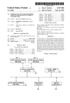
US006289332B2
(12)
United States Patent
(10) Patent N0.:
(45) Date of Patent:
Menig et al.
(54)
INTEGRATED MESSAGE DISPLAY SYSTEM
FOR A VEHICLE
(75)
Inventors: Paul M. Menig, Tigard; Richard A.
Bishel, Beaverton, both of OR (US);
3/1974 Sumiyoshi et al. ............... .. 340/52 F
12/1974 Hynes .............................. .. 340/52 F
3,987,439
10/1976 Spaniola
4,053,868
4,072,924
10/1977 Cox et al.
2/1978 PomerantZ
Brandt, Lake OsWego, OR (US)
(73) Assignee: Freightliner Corporation, Portland,
OR (US)
Sumida .......... ..
.. 340/52 F
4,356,470
10/1982 Kogawa et al. .
340/52 F
4,400,779
4,475,380
8/1983 Kosuge et al. ..... ..
10/1984 Colovas et al. .... ..
2/1985 Grohmann et al. ..
8/1985
4,564,905
4,570,226
1/1986 Masuda et al. ..
. 364/424
2/1986 Aussedat ............................ .. 364/442
364/442
. . . ..
360/5
OTHER PUBLICATIONS
154(a)(2).
Sayer, First Committee Draft of SAE 12399, pp. 1—16, Sep.
Subject to any disclaimer, the term of this
patent is extended or adjusted under 35
CELECT R0adRelayTM—User’s Guide, Cadec Systems,
Inc., Londonderry, NH, pp. 1—32, 1993.
9, 1998.
(List continued on next page.)
Primary Examiner—Williarn A. Cuchlinski, Jr.
Assistant Examiner—Ronnie Mancho
(74) Attorney, Agent, or Firm—Klarquist Sparkrnan
Carnpbell Leigh & Whinston LLP
(60)
Provisional application No. 60/122,167, ?led on Feb. 26,
(51)
Int. Cl.7 ............................. .. G05D 1/00; G06F 7/00;
(57)
1999.
extendable, prioritized rnessage scherne. Using this scheme,
the message system acts as a centralized rnessage provider
for variety of alerts and operating data originating through
US. Cl. ................................. .. 707/1; 701/29; 701/30;
out the vehicle. The message system de?nes a hierarchy of
701/31; 701/33; 701/36; 340/435; 340/438;
340/439; 340/440; 340/441; 340/903; 180/167;
180/169; 342/69; 342/70; 342/72
message levels, each having a unique output protocol. The
protocol de?nes attributes associated with messages at a
particular level such as textual or graphical rnessage, an
auditory alert, as Well as the scheme for playing these
Field of Search .................................. .. 701/1, 29, 30,
701/31, 33, 36; 340/903, 435, 439, 440,
441, 438; 180/169, 167; 342/70, 72, 69
messages and alerts. The system integrates a variety of
subsysterns that conventionally have separate driver inter
faces such as a collision warning system and an adaptive
References Cited
cruise control system.
U.S. PATENT DOCUMENTS
5/1972
ABSTRACT
An integrated message system for a vehicle provides an
G06F 17/00; G06F 19/00
3,665,383
.......
(List continued on next page.)
Appl. No.: 09/272,878
Filed:
Mar. 18, 1999
(56)
Decker et al.
This patent issued on a continued pros
Related US. Application Data
(58)
364/444
73/114
4,502,124
U.S.C. 154(b) by 0 days.
(52)
9/1981
4,533,962
ecution application ?led under 37 CFR
1.53(d), and is subject to the tWenty year
patent terrn provisions of 35 U.S.C.
(21)
(22)
340/413
340/52 F
340/52 F
5/1978 Kosuge .............................. .. 340/414
3/1981 JuhasZ et al. ...................... .. 364/424
4,287,503
Kirn; Jared A. Powell, both of
Portland, OR (US); Peter Charles
Notice:
3,798,596
3,852,712
4,090,194
4,258,421
Goetz Renner, Esslingen (DE); Nicolae
Ghitea, J r., Tigard, OR (US); Chris
US 6,289,332 B2
*Sep. 11, 2001
22 Claims, 9 Drawing Sheets
Fales ................................ .. 340/52F
EN GIBIIEE BRAKE
CU
110
F112
5
108
FRONT f
SENSOR
SIDE
104
36
/ 142
ANTI-LOCK
COLL'S'ON
ENGINE
ECU
WARNING/ACO
SENSOR
S'DE
SENSOR
102
140
TRANSMISSION
ECU
BRAKE
ECU
ECU
DISPLAY /
144
SHIFT
I I
4150
CONTROL
\
\
SWITCHES
\
130
114
DATA
LOGGING/
120%
UN”
/
116
US 6,289,332 B2
Page 2
McGehee, Dingus, and Horowitz, “An Experimental Field
US. PATENT DOCUMENTS
4,663,718
4,706,083
4,787,039
4,845,630
5,121,112
5,148,702
5,173,856
5,189,619
5,241,295
5,303,163
5,309,139
5,327,117
5,347,260
5,432,497
5,457,439
5,463,370
5,510,776
5,525,959
5,529,139 *
5,572,428
5,572,449
5,646,612
5,648,755
5,659,304 *
5,661,658
5,678,196
5,693,876
5,731,977
5,748,477
5,757,268
5,764,139
5,771,007
5,802,545
5,839,534
6,009,355 *
6,025,789 *
6,025,796 *
5/1987
11/1987
11/1988
7/1989
6/1992
9/1992
12/1992
2/1993
8/1993
4/1994
5/1994
7/1994
9/1994
7/1995
10/1995
10/1995
4/1996
6/1996
6/1996
11/1996
11/1996
7/1997
7/1997
8/1997
8/1997
10/1997
12/1997
3/1998
5/1998
5/1998
6/1998
6/1998
9/1998
11/1998
12/1999
2/2000
2/2000
Augello et a1. .................... .. 364/444
BaatZ et a1. .
340/825.06
Murata
364/424.01
Stephens
.. ...
. . . . . . ..
364/442
Nakadozono
340/870.16
Gulick, Jr.
.... .. 73/114
Purnell et a1. .
Adachi et a1. .
364/424.04
364/426.04
Madau
............................... .. 340/461
Ebaugh et a1. ..................... .. 364/550
Austin
Test of Automotive Headway Maintenance/Collision Warn
ing Visual Displays,” Proceedings of the Human Factors
and Ergonomics Society 38th Annual Meeting, 1994, pp.
1099—1103.
Braun, Sansing, and Silver, “The Interaction of Signal Word
and Color on Warning Labels: Differences in Perceived
HaZard,” Proceedings of the Human Factors and Ergonom
ics Society 38th Annual Meeting, 1994, pp. 831—835.
“Operational Testing of Adaptive Cruise Control,” Automo
tive Engineering International, Sep., 1998, pp. 63—71.
....... ..
.
340/462
Clarke, Peter, “Adaptive Cruise Control is About to Take a
Kohsaka .... ..
.
340/525
GinZel et a1.
Briski et a1.
. 340/438
. 340/525
Spin,” Systems and Software, Electronic Engineering Times,
Kuhn ............ ..
.
Ishikawa et a1.
340/435
.................. .. 340/439
Murphy et a1. ............... .. 340/825.17
PrZybyla et a1.
340/438
Kurahashi et a1.
Ishida et a1.
. 180/169
. 364/461
Tang et a1. ..
. 364/565
Byon ..... ..
. 340/903
Yagihashi ........................... .. 340/439
Chakraborty ....................... .. 340/903
Putt et al.
364/481
Katoh
. . . . . . . . . . . . .
Warnings: An Isoperformance Application,” Proceedings of
the Human Factors and Ergonomics Society 38”1 Annual
Meeting, 1994, pp. 1104—1108.
Detroit Diesel—ProDriverTM—User’s Manual, Detroit Die
sel Corporation, 1994.
“Operating & Error Codes—Fuel—Tach DBF & DB—2 for
Electronic Engines,” Series 925/205, FloScan Instrument
Company, Inc.
Caterpillar OWner’s Manual—Caterpillar Driver Informa
tion Display, Feb. 1995.
. . . ..
364/461
Nojima et a1. ..................... .. 340/461
Coverdill
1998, pp. 130—132.
Appendix C, Standard Protocol, pp. 12—19.
Braun, Curt C., Lori Sansing, Robert Kennedy, N. Clayton
Silver,“Signal Word and Color Speci?cations for Product
.... .. 73/114
. 364/426.044
Toffolo et a1. ..................... .. 340/461
Arai et a1.
Engineering/Automotive Engineering International, Nov.
455/54.1
Doyle ........... ..
Ghitea, Jr. et a1.
Taniguchi et a1. .
Oct. 26, 1998.
“EVT—300 Collision Warning System & SmartCruise,”
Eaton VORAD®, Speci?cation Sheet, 1998.
“EVT—300 Technical Highlights,” Eaton VORAD®, Speci
?cation Sheet, Collision Warning System, 1998.
“Radar—Based Adaptive Cruise Control for Trucks,” Truck
. 340/903
............................. .. 711/35
Chakraborty et a1. ............. .. 180/169
Obradovich et a1. .
Lane et a1.
701/1
. 340/933
Crosby, II
. 342/701
OTHER PUBLICATIONS
Detroit Diesel ProDriverTM—Flyer, 1994.
Appendix C, Electronic Dash Display, Feb. 2, 1996.
“Joint SAE/TMC Electronic Data Interchange BetWeen
Microcomputer Systems in Heavy—Duty Vehicle Applica
tions,” 1988—01.
* cited by examiner
U.S. Patent
Sep. 11, 2001
Sheet 2 0f 9
520
KEYPAD
F|G- 2
DISPLAY
DEVICE
M
MEMORYZJ1O
512 =
RAM
EEPROM
214
206’
S
522
\
2Jo4
ROM
US 6,289,332 B2
2oL2
‘
'
h
‘'
" >
206
CPU
PORT
INTERFACE
$
208-)
5
U.S. Patent
Sep. 11,2001
Sheet 3 0f 9
US 6,289,332 B2
w? Pmw
\
.Ewm
wow Om]
\
N8
\
O
U.S. Patent
Sep. 11,2001
Sheet 4 0f 9
US 6,289,332 B2
FIG. 5
LEVEL 1 - DANGER
/5OO
DANGEFI
STOP ENGINE QUICKLY I10
'90s
\ [S DANGER
TOP ENGINE QUICKLY I10
]
FIG. 6
LEVEL 2 - WARNING
600
/
WARNING
.
LOW OIL PRESSURE .10
/_\ /
\
MESSAGE
@EAQ
602
I5 604
TIME
I‘ SELECTABLE 612
DRIVER
DEFAULT SCREEN .1 0
ILOW OILWARNING/
J
PRESSURE I10
606
628
VI
\66”
/
¢3%EE€2I“D
‘\ILoW OIL PREssuRE IIQI/
WARNING
U.S. Patent
Sep. 11,2001
Sheet 5 0f 9
US 6,289,332 B2
FIG. 7
LEVEL 3 - CAUTION
700
/
CAUTION
/\/
MESSAGE
702
TURN SIGNALON I10
\
REPEAT
TIME
z‘
6
704
\
r 712
C
[Dgli'lllggssigzgg?hfo]
\ 6 71°
706
O
AUTI N
TURN SIGNAL ON I10
J
708
/
SSECOND
_\[TURN SIGNALON
CAUTION I10.] / DELAY
FIG. 8
LEVEL 4 - NOTE
/
800
NOTE
/-\ / LOW WIPER FLUID I10
\
MESSAGE
REPEAT
mm)
/
K 808
[DRIVER
DEFAULT SELECTABLE]
SCREEN '10
806
SSECOND
J 804
DELAY
NOTEFLUID n10]4
[LOW WIPER
U.S. Patent
Sep. 11,2001
Sheet 6 0f 9
US 6,289,332 B2
FIG. 9
FIRST STAGE DISTANCE ALERT
DANGER
AHEAD
90o
SECOND STAGE DISTANCE ALERT
DANGER
AHEAD
..
902
THIRD STAGE DISTANCE ALERT
DETECT LIGHT
- )“2 IIIIQG
/ +
0094376 Ml)
CREEP ALERT
MOVING
sLQw
k 908
U.S. Patent
Sep. 11,2001
Sheet 7 0f 9
US 6,289,332 B2
FIG. 10
MESSAGE
1
(Tl-PW”
DISPLAY MESSAGE
DATABUS MESSAGE
COMMENT
DANGERAAHEAD 2192266488111401CHKSUM J1587PRIORITY1
DANGERA AHEAD 219226648811 1402CHKSUM J1587 PRIORITY1
DANGER A AHEAD 21922664881 1 140 3 CHKSUM J1587 PRIORITY 1
NOAR
DISPLAY
R AD
DETECTMESSAGE
LIGHT ON 21922664881 1 140 4 CHKSUM J1587 PRIORITY 1
VEHICLE MOVING SLOW 21922664881 1 1405 CHKSUM J1587 PRIORITY 1
AAAAAAAA
TAI?JLLgVILERIAN?E» 21922664881 1 1406 CHKSUM J1587 PRIORITY2
TALERT/HDWY RANGE
21922664881 1 1407 CHKSUM J1587 PRIORITY 2
TALERT/HDWY RANGE
21922664881 1 1408 CHKSUM J1587PRIOR1TY2
EI'TFTTFI MAX>
<
10
11
12
cc-Trrn MAX>
RAN?EX>
< |al?TALERT/HDWY
EEC-ZED]
21922664881 1 140 9 CHKSUM J1587PR1ORITY2
SET A-ERT/HDWY RANGE
SET ALERT/HDWY RAN GE
21922664881 1 14010CHKSUM J1587 PRIORITY2
ET ALERT/HDWY RANGE
21922664881 1 14012CHKSUM J1587 PRIORITY2
<|v| N EDIE-ID] MAX>
<MN IIEEIIU MAX>
< N
IIIIIIII! MAX>
ST A_EHT D
ANGE
TTT'ITI'T- MAX>
14
21922664881 1 14011 CHKSUM J1587 PRIORITY2
21922664881114013CHKSUM J1587PRl0R|TY2
SETALERTVOLUME
-:1:1:1:1:1:1:1
21922664881114014CHKSUM ATMINI
J1587PRL0R'TY2LSED'NG
INCR MENTO
I\FETALERTVOLUMEIVI
21922664881114015CHKSUM
SETALERTVOLUME
21922664881114816CHKSUM
<M|N
MAX>
OF RX
EE-IEEED MAX>
17
18
19
20
2‘
22
SETALERT VOLUME
<MlN 1:11-3:11 MAX>
SETALERTVOLUME
INCREMENT 11
REMENT 2)
21922664881 1 14817CHKSUM
REMENTS)
21922664881114018CHKSUM
1:. E O REMENT 4)
<M|N 1:1:1:1:-:1:1:1 MAX>
SETALERTVOLUME
41 HK M
INCREMENT 5)
< MI N EDIE-I] MAX> 219226648811169C SU
SET ALERT VOLUME
21922664881 1 14020 CHKSUM a. 1587 "U I IORLTY 2
<M|N [EDIE-3 MAX>
(SETI'LNG AT INCREMENT 6)
J1587P lORI 2
<1/11AFELJELEAQLIHME1AA» 21922664881114°21CHKSUM (SETTING ATIVCREMENT 71
HEADWAY DATA ONLY
23
24
MENTS 14111
DES/T111812
219 226 8 48 8 2 16 146 eee CHKSUM J1587 PRIORIT Y 2
PRIORITY2
21922664881114°23CHKSUM J1587
ACCIDENT
RECONSTRUCT.
CONFIRMATION SCREEN
J1587PR|OR|TY2
21922664881 1 146 24 CHKSUM ACCIDENTRECONSTRUCT
DATA SAVE FAILURE
U.S. Patent
Sep. 11,2001
Sheet 9 0f 9
US 6,289,332 B2
FIG. 12
i1204 1206
CRUISE SET TO: 55MPH
1218
HEADWAY SET TO: 30s L
1216 .
WARNING
RADAR CRUISE OFF
RADAR HEADWAY SET LN‘
[ MIN
J A202
WARNING
RADAR CRUISE FAIL
1208
1210
DANGER
AHEAD
1212 DANGER
1220/
SET
DANGER‘
65
AHEAD r1214
1222/ DANGER
FIG. 13
DRIVER SELECTABLE
130°
DEFAULT/ALERT 19G
1308
\
\ 1306
1 s04
DRIVER SELECTABLE
DEFAULT/ALERT $98
1302
1308
\
13101306
US 6,289,332 B2
1
2
INTEGRATED MESSAGE DISPLAY SYSTEM
FOR A VEHICLE
instrurnentation control unit determines whether to override
the current message With a collision Warning alert based on
the relative priority of the alert and the current message. The
collision Warning alerts use a combination of visual and
auditory Warnings that groW progressively more intense as
RELATED APPLICATION DATA
This application claims priority to co-pending US. patent
application Ser. No. 60/122,167, ?led Feb. 26, 1999,
the degree of danger of a collision danger increases. This
entitled, “Integrated Message Display System for a Vehicle”,
by Paul Menig, Richard Bishel, Nick Ghitea, Chris Kirn,
Jared PoWell, and Peter C. Brandt, Which is hereby incor
porated by reference.
10
adaptive cruise control messages into the systern’s central
TECHNICAL FIELD
The invention relates to audio-visual message displays for
vehicles that provide operating, diagnostic, and Warning
15
information to the driver.
iZed rnessage scheme. The instrurnentation control unit
prioritiZes adaptive cruise control messages in a similar
manner as collision warning messages. In particular, it
determines Whether to override the current message based
on the relative priority of the current message and a neW
BACKGROUND
adaptive cruise control message. In one implementation, for
example, the instrumentation control unit manages the dis
play of three types of adaptive cruise control rnessages:
function set messages, system failure messages, and danger
ahead messages. It generates function set messages in
Over the past several years, a variety of vehicle electron
ics products have been developed to assist drivers, and
provide vehicle operating, trip and diagnostic information.
This is particularly true in long-haul trucks, Where a number
of options are available such as collision warning systems,
adaptive cruise control, and Wireless communication sys
terns. Sorne collision warning systems use radar to apprise
the driver of collision dangers. Adaptive cruise control is an
advanced feature of collision warning systems that uses
approach eases the driver’s Workload because the collision
alerts are integrated into the instrumentation control unit’s
message center, Which provides a centraliZed source of
information to the driver.
Yet another aspect of the invention is the integration of
response to user input, such as When the driver sets a desired
headWay for the adaptive cruise control system. It generates
25
system failure messages in response to detecting a failure of
radar and the vehicle’s cruise control system to maintain a
some aspect of the adaptive cruise control system. Finally, it
generates danger ahead messages in response to collision
Warning events that occur While the vehicle is in adaptive
desired folloWing distance (called “headWay”). In addition
cruise control mode.
to these neW electronics products, existing cornponents noW
typically include electronic controls that can provide addi
transmission messages into the systern’s centraliZed mes
tional vehicle diagnostic and operating data.
While these electronic products can provide useful infor
sage scherne. The instrurnentation control unit integrates the
display of transmission messages, such as the current gear
Another aspect of the invention is the integration of
rnation to the driver, they can also overload the driver with
information. Even With careful design of displays and indi
35
cator lights for each neW feature, the driver can easily
and mode of the transmission, by displaying this information
along With the display of a default screen or an alert screen.
become overwhelmed by the displays associated With these
Further features of the invention will become apparent
With reference to the folloWing detailed description and
neW products. As such, the driver may ignore, or Worse,
accompanying draWings.
becorne distracted by the displays.
BRIEF DESCRIPTION OF THE DRAWINGS
SUMMARY OF THE INVENTION
The invention provides an audio-visual message system
for a vehicle that receives information about operating
conditions from a variety of sources throughout the vehicle
and generates visual and auditory outputs via a centraliZed
45
message center. The system includes an instrurnentation
control unit that manages the output of alerts through a
visual display and audio transducer. The instrurnentation
control unit receives information about operating conditions
from other electronic control units in the vehicle. In
response, the instrumentation control unit determines the
appropriate messages to generate based on a general, eXtend
able prioritiZation scheme.
The system prioritiZes alerts based on their relative impor
tance. It organiZes alerts into levels of importance, Where
each level has a corresponding visual and auditory alert that
55
operation of the highest priority alert, a DANGER alert.
FIG. 6 illustrates the operation of the neXt highest priority
alert, a WARNING alert. FIG. 7 illustrates the operation of
the neXt highest priority alert, a CAUTION alert. Finally,
FIG. 8 illustrates the operation of the loWest priority alert, a
distinguishes it from other levels. When an event is detected
that triggers an alert, the instrumentation control unit over
rides a default screen and plays the corresponding alert.
When more than one alert is activated, the instrumentation
control unit resolves con?icts based on the priority of each
alert.
Another aspect of the invention is the integration of
collision warning messages into the systern’s rnessage
scheme. A collision warning system cornrnunicates collision
Warning conditions to the instrumentation control unit. The
FIG. 1 is a block diagram illustrating an implementation
of electronic subsystems and their interconnection With an
instrurnentation control unit.
FIG. 2 is a diagram illustrating the instrumentation con
trol unit in FIG. 1.
FIG. 3 is a diagram illustrating a vehicle dash, and the
positioning of the instrumentation control unit’s display on
the dash.
FIG. 4 is a diagram illustrating the keypad for the instru
rnentation control unit.
FIGS. 5—7 are diagrams illustrating the operation of four
levels of prioritiZed rnessage displays. FIG. 5 illustrates the
NOTE alert.
FIG. 9 is a diagram illustrating rnessage displays of
collision detection Warnings integrated into the message
65
center of the instrumentation control unit shoWn in FIGS. 1
and 3.
FIG. 10 is a table illustrating a list of collision detection
display messages and their corresponding priority and data
bus rnessage forrnat.
US 6,289,332 B2
3
4
FIG. 11 is a diagram illustrating screens in the message
center for identifying the driver to the system for the purpose
fuel How is directly related to the amount of time that the
solenoid valve is closed. This time period determines the
of maintaining a driver speci?c data record of operating
events, including collision detection events.
volume of fuel injected into a cylinder per revolution. By
determining the amount of time that the solenoid valves are
closed, the engine ECU can compute the amount of fuel
FIG. 12 is a diagram illustrating screens in the message
consumed by the engine. The engine ECU calculates the fuel
?oW rate from the dWell of the injection pulse and the engine
center for reporting adaptive cruise control information.
FIG. 13 is a diagram illustrating hoW transmission infor
mation is integrated into the message center.
speed.
number of electronic control units (ECUs, 100—110) inter
The engine ECU measures the vehicle’s road speed. A
speed control senses the speed of rotation of the tail shaft of
the truck and converts it into road speed. A hall effect sensor
located on the tail shaft generates an analog signal com
prised of a series of pulses representing the rotation rate of
the engine. The engine ECU is programmed to read this
digital value and derive the instantaneous speed in miles per
hour.
The engine ECU also monitors a variety of other vehicle
connected via data links 112, 114. An instrumentation con
operating parameters, including RPM, engine torque and
trol unit (ICU) 100 located in the dash of the vehicle
provides an integrated message center for other subsystems
throttle position. These parameters are transferred to the ICU
100 over the data link 114.
The transmission ECU 104 controls the trucks transmis
sion. The speci?c type of ECU varies depending on the
DETAILED DESCRIPTION OF THE
INVENTION
10
System Implementation OvervieW
FIG. 1 is a block diagram illustrating the system archi
tecture of electronic control units in an implementation 15
installed in a truck. The system architecture includes a
in the vehicle, including the engine ECU 102, transmission
ECU 104, anti-lock brake ECU 106, and collision Warning
ECU 108. In addition, the system includes a data logging
transmission vendor, and the type of transmission, e.g.,
unit 116, Which monitors messages communicated over the
data link and records operating data in response to detecting
25
events.
manual, automatic or automated mechanical transmission.
EXamples of transmission systems that are controlled via
ECUs include the Eaton Fuller AutoShift® heavy-duty
automated truck transmission and the Meritor SureShiftTM
transmission system.
The integrated message center of the ICU 100 in FIG. 1
includes a visual display 118 and audio transducer (i.e., a
speaker) 120 for generating audio-visual alerts. The visual
The transmission ECU receives driver instructions via a
display includes a display screen 122 as Well as indicator
driver interface in the cabin of the truck. One possible
implementation of the driver interface is a column mounted
shift control 150 that communicates shift command inputs to
lights (e.g., 124a—c). The driver can enter input to the ICU
via an input device 126 (e.g., a keypad) and, in some
implementations, via discrete sWitches 128 (e.g., rocker
sWitches, push buttons). SWitches and other dash controls
that impact the operation of the ICU may be Wired to the
a transmission ECU. For more information on this type of
35
ICU or to other ECUs, or both. For example, a collision
Warning system and/or adaptive cruise control system may
include input sWitches located on the dash. These sWitches
can be Wired directly to the collision Warning ECU 108,
Which in turn communicates input from the sWitches to the
ICU. Conversely, other sWitches may be Wired directly to the
ICU, Which in turn, communicates input from the sWitches
Joseph LocZi, and Jason Stanford, Which is hereby incorpo
rated by reference.
The anti-lock brake ECU 106 controls the anti-lock
brakes on the truck. EXamples of anti-lock brake systems
controlled via an ECU include the WABCO ABS from
to another ECU via the data link 114.
The engine ECU 100 shoWn in FIG. 1, controls and
monitors the operation of the engine. Like the other ECUs,
the engine ECU includes a programmed data processor and
memory for storing computer programs and data. The data
Meritor WABCO Vehicle Control Systems, Bendix
45
The collision Warning ECU 108 controls a collision
(CWS) includes a front sensor 140, side sensor 142, side
and monitor engine performance.
sensor display 144, and sWitches 128 (e.g., an ON/OFF
The engine ECU also includes a variety of sensors and
engine’s cylinders.
AntiLock Systems from Allied Signal Truck Brake Systems
Company, and Bosch AntiLock Brake Systems.
Warning system on the truck. The collision Warning system
processor eXecutes routines stored in the memory to control
controls used to monitor and control the engine. One impor
tant function of the engine ECU is the control of the throttle.
The engine ECU controls the fuel rate by issuing control
signals to a fuel injector that controls the How of fuel to the
driver interface, see co-pending patent application Ser. No.
09/258,649, entitled “Lever Assembly for an Electronically
Controllable Vehicle Transmission”, ?led Feb. 26, 1999, by
Paul Menig, Michael von Mayenburg, Nasser Zamani,
sWitch, volume control, and collision Warning range/
adaptive cruise headWay control). A programmed CPU on
the CWS ECU 108 receives information about nearby
objects from the front sensor 140 and side sensor 142,
55
computes collision Warning conditions, and communicates
Warnings to the ICU 100. Based on information from the
front sensor 140, the CWS ECU 108 measures the range,
The ECU includes several sensors that monitor vehicle
operating data, including a speed sensor, an RPM sensor, a
distance, closing speed, and relative speed to vehicles and
throttle position sensor and a cruise status sensor. Some
other objects in its ?eld of vieW. For radar-controlled
vehicle operating parameters are computed from measured
data. For eXample, the engine torque is computed using a
systems, the front sensor 140 is a radar antenna. Other types
of sensors may be used as Well, such as infra-red sensors.
mathematical formula that expresses engine torque as a
Side sensors 142 located on the side of the truck detect
function of measured parameters, including fuel rate and
turbo boost pressure.
The engine ECU determines the amount of fuel supplied
vehicles in the driver’s blind spots. In response to detecting
an object via the side sensor, the CWS generates a Warning
to the cylinders in the engine by controlling the solenoid
valves that inject fuel to the engine cylinders. The rate of
65
indicator on the side sensor display 144.
In addition to providing collision Warnings, the CWS
ECU 108 operates in conjunction With the engine ECU 102,
US 6,289,332 B2
5
6
anti-lock brake ECU 106 and engine brake ECU 110 to
communicated among microprocessors connected to a
provide Adaptive Cruise Control (ACC). Adaptive cruise
shared data link, and is speci?cally adapted for use With
control is an application of the collision detection system
SAE 11708.
According to SAE 11708/11587, the ECUs on the data
that uses data detected from the front sensor to maintain
headWay (i.e., the following distance) betWeen the truck and
link communicate by passing messages to each other. The
the vehicle in front of it. The ACC system adjusts the
vehicle’s speed from the “set speed” established for cruise
ECUs can be either receivers, or receivers and transmitters.
In this particular implementation, the instrumentation con
trol unit 100 is both a transmitter and receiver. The engine
control to maintain a safe folloWing distance from a sloWer
vehicle. To control vehicle speed, the ACC system sends
control messages via the 11939 data link to: 1) the engine
ECU for throttle control, 2) the engine brake to actuate
ECU acts as both a transmitter and receiver as Well. As a
10
speed, fuel rate, engine torque, RPM, throttle position,
engine retarder braking, 3) the anti-lock brake system to
initiate automatic braking, and 4) the transmission control to
doWnshift the transmission. When the sloWer vehicle
increases its speed or changes lanes, the ACC resumes the
speed to return to the desired set speed. For more informa
tion on adaptive cruise control, see US. Pat. No. 5,839,534,
engine status, etc. It receives messages regarding cruise
control functions.
In the 11587 format, a message includes the folloWing: 1)
15
Using Standard Engine Control Modes,” Which is hereby
20
The CWS ECU 108 in the current implementation is part
of the EVT-300 collision Warning system from Eaton
VORAD Technologies, L.L.C. of San Diego, Calif. The
ACC functionality is part of the SMARTCRUISE® adaptive
cruise control system from Eaton VORAD Technologies.
Other collision Warning and adaptive cruise control systems
25
30
The engine brake ECU controls engine braking by con
trolling the discharge of gases from the engine’s cylinders.
While shoWn as a functionally separate unit, the engine
brake ECU is typically incorporated into the engine ECU.
35
The Data Links
40
applications; and 2) a data link 112 designed according to the
SAE 11939 Serial Control and Communication Vehicle
45
implementations, it may also use the 11939 data link to
connect the ICU With other ECUs.
The 11708 data link is comprised of a tWisted pair cable
operating at 9600 baud. The data link forms a communica
tion channel among the electronic control units coupled to it.
Electronic control units generate a digital signal on the data
ers only act on a message if programmed to do so.
In some cases tWo or more transmitters may attempt to
broadcast a message at one time, giving rise to a collision.
To resolve a con?ict among transmitters, messages have a
55
priority over lesser dominant messages. Since a loWer pri
ority message is blocked by a higher priority message, the
60
transmitter of the loWer priority message must Wait and
retransmit the message after another lull. An ECU on the
data link Will continue to attempt to send a message until it
The ECUs connected on the netWork communicate With
This standard de?nes one format for data and messages
priority according to their message identi?ers. The MIDs of
higher priority transmitters have a greater number of bits set
at a logic level one. When more than one message is
broadcast at a time, the more dominant message takes
vious to signal degradation.
computer Systems and Heavy Duty Vehicle Applications.”
particular implementation, the length of the lull is 200
milliseconds. After detecting this lull, the ECU attempts to
transmit its message. The transmitter broadcasts its message
onto the data link. Each of the ECUs that operate as receivers
on the data link Will receive the message. HoWever, receiv
sors to convey information to the ICU. For alternative
each other according to protocols de?ned in SAE 11708 and
SAE 11587. The SAE 11587 standard is entitled “Joint
SAE/TMC Electronic Data Interchange BetWeen Micro
accessing the data link and constructing messages for trans
fer over it. It also de?nes a method for resource contention
among the ECUs on the data link.
An ECU Wishing to transmit data on the data link ?rst
Waits for a lull in transmission of data on the data link. In this
NetWork standard. While the current implementation prima
link by applying a voltage differential betWeen the tWo Wires
in the cable. A voltage differential above a speci?ed thresh
old represents a logic high value, While a voltage threshold
beloW a speci?ed threshold represents a logic loW value.
This type of data link is particularly advantageous for hostile
environments because the signal is more robust and imper
character (PID). The parameter identi?ed by the PID directly
folloWs the PID. The SAE 11587 supports different data
formats including a single character, a double data character
or more than tWo data characters representing the parameter
data. Several parameters can be packed into a message,
limited by the maXimum message siZe as noted above.
Again, in this implementation, the ECUs communicate
data links 112, 114: 1) a data link 114 designed according to
rily uses the 11708 data link as a shared communication path
betWeen the ICU and the other ECUs, it also uses dedicated
Wiring connections directly betWeen some ECUs and sen
messages. According to the SAE 11587 standard, the ?rst
character of every parameter is a parameter identi?cation
With each other over one of the data links 114 according to
the SAE standard 11708. The standard describes methods for
The implementation shoWn in FIG. 1 uses tWo separate
SAE 11708, a standard for serial data communication
applications.
tion about one or more parameters contained Within the
ADC. ADC adaptive cruise control systems include radar
betWeen microcomputer systems in heavy duty vehicle
standard. The message identi?cation numbers are assigned
to transmitter categories as identi?ed in SAE 11587. The
MID portion of a message speci?es the origin or transmitter
of the message. In the majority of cases, messages are
broadcast on the data link Without specifying a receiver.
HoWever, the message format can be extended to include the
MID of a receiver after the MID of the transmitter for special
The messages passed among the ECUs convey informa
may be used in the alternative. One eXample of an alterna
tive system is the ADC. distance control system from
based sensors and infrared based sensors.
a module ID (MID), 2) one or more parameters, and 3) a
checksum. The number of parameters in a message is limited
by the total message length de?ned in the SAE 11708
entitled “System and Method for Intelligent Cruise Control
incorporated by reference.
transmitter, it sends messages to the ICU regarding road
is successfully broadcast to the data link.
65
The Instrumentation Control Unit
FIG. 2 is a functional block diagram illustrating the
architecture of the ICU 200 shoWn in FIG. 1. The ICU has
US 6,289,332 B2
7
8
a CPU 202, memory 204 and a port interface 206 for
connecting the unit to the J 1708 data link 208. The memory
gallons and average MPG), etc. The trip and leg keys 406,
408 are used to display the miles traveled, elapsed hours, and
204 includes programmable ROM (EEPROM) 210, RAM
fuel consumed for a trip or a leg of a trip.
212 and permanent ROM 214. The routines for controlling
the ICU are stored in ROM 210, While re-con?gurable data
keys:
The keypad also includes the folloWing general-purpose
is stored in the EEPROM 214.
In one speci?c implementation, the ICU has a 68HC16
1. Left ArroW Key (410)
2. DoWn ArroW Key (412)
microprocessor from Motorola Corporation, and its memory
con?guration 204 includes EEPROM, ROM, and RAM.
This speci?c ICU has 8 KB of external EEPROM, 500K of
3. Right ArroW Key (414)
4. Set/Reset Key (416)
5. Event Key (418)
10
ROM and 64K of RAM. The internal memory of the ICU
These keys can be used to scroll through message screens
on the display, enter data, clear messages, etc. For example,
these keys can be used to enter con?guration data such as the
includes 1 Mbyte of RAM and 1 Mbyte of ROM. These
speci?cations are unique to the implementation, but Will
vary from one implementation to the next. A variety of
microprocessors and memory systems can be used to imple
ment the functionality of the instrumentation control unit.
Preferably, the processor used in the ICU should have at
least a 16 bit microprocessor. The speed of the processor can
vary, but should be sufficient to manage the message center
15
The event key enables the driver to log an event. In
response to this event, data logging unit 116 in the system
persistently stores performance and ECU fault data from the
data link occurring during a time period starting a predeter
functions described beloW Within a 200 ms time increment.
mined time before and after the event. For more information
on this data logging function see US. Pat. No. 5,802,545,
The ICU also includes an input device 220 and a display
device 222. In the current implementation, the input device
is a ten-key keypad. The display device 222 provides a
textual and graphical output to the driver. The current
implementation of the display device is a tWo by 20 vacuum
volume object detection range for collision Warnings, and
the set speed and headWay for adaptive cruise control.
Which is hereby incorporated by reference.
Finally, the keypad includes an acknoWledgment key 420.
25
When the ICU generates a Warning message, the driver can
use the acknoWledgment key to indicate that he/she
?uorescent display.
acknoWledges the Warning. The ICU responds differently to
The ICU used in this implementation is manufactured by
this key depending on the type and state of the Warning
Joseph Pollak of Boston, Mass. for Freightliner Corporation,
condition, as explained in more detail beloW.
and is available as a replacement part from Freightliner
Corporation.
General Vehicle Operating Information and
Message PrioritiZation
Example of the Dash Layout
FIG. 3 is a diagram illustrating the position of the ICU’s
display 346 and an input device 344 among the instruments
During normal operation of the truck, the ICU displays
vehicle operating information, including a bar graph illus
35
and controls on a dash 322 in one implementation. The dash
average fuel economy, and an odometer reading. For more
322 shoWn in FIG. 3 includes a number of gauges, including
information, see US. Pat. No. 5,693,876 and co-pending
for example, an analog speedometer 324 and tachometer
patent application Ser. No. 08/982,117 entitled, “Fuel Use
Ef?ciency System ForAVehicle For Assisting The Driver To
Improve Fuel Economy,” Which are hereby incorporated by
326, a fuel gauge 328, etc. Instruments located at the dash
include a parking brake sWitches 330, 332, heating,
ventilation, and air conditioning (HVAC) controls 334—340,
reference. The driver can directly access other information
etc.
In addition to these discrete gauges, instruments and
indicator lights, the dash also includes the user interface for
the control unit, Which is referred to as the instrument
control unit in this implementation. The user interface of the
instrument control unit includes a display device 342 and an
input device 344, both located on the dash.
via the trip, fuel, leg, and temp input keys as explained
45
These operating conditions include, for example, park
The display device 346, in the current implementation, is
etc. The ICU generates and controls the display of these
play (LCD) or raster display device. The input device 344 of
the ICU is a keypad including dedicated and general purpose
function keys. Alternative implementations and con?gura
55
reaction from the driver and is used for extremely serious
problems. A Level 2 Warning indicates a very serious
problem and also requires immediate reaction from the
driver.
1. Temperature (402)
Level 3 Warnings indicate a serious problem and require
2. Fuel (404)
action soon. Level 4 Warnings consist of status information
and are intended to require action only When convenient.
3. Trip (Miles, hours and fuel) (406)
4. Leg (Miles, hours and fuel) (408)
402), fuel ef?ciency information 404 (e.g., fuel used in
overWrite screens according to a prioritiZation scheme. In
the current implementation, for example, there are four
levels of alerts: Level 1 “Danger”, Level 2 “Warning”, Level
3 “Caution”, and Level 4 “Note” or “Message.” A Level 1
Warning is a message intended to evoke an immediate
The keypad of FIG. 4 includes the folloWing dedicated keys:
The dedicated keys are used to request speci?c informa
tion such as the current outside air temperature (temperature
above.
In addition, the ICU displays a variety of “priority over
Write” screens that override the normal operating screens
When certain operating conditions are detected.
brake on (While vehicle is moving), high coolant
temperature, loW oil pressure, air ?lter clog, turn signal on,
a tWo by 20 vacuum ?uorescent display. Alternative imple
mentations are also possible such as a Liquid Crystal Dis
tions of the input device are also possible.
FIG. 4 is a diagram of one implementation of the keypad.
The keypad includes a number of keys to enable the driver
to query the ICU for information and to control its operation.
trating the rate of change of fuel economy and the short term
The driver can acknoWledge an alert by pressing the
65
acknoWledgement key in the keypad of the ICU.
Each of the four levels of alert is associated With a
predetermined message protocol, including a visual and
US 6,289,332 B2
10
audio indicator. The following table provides an example of
the message protocols associated with the four warning
levels. When a priority overwrite message is activated, the
the acknowledgement key. The repeat time of the message is
a pre-determined parameter in the ICU that controls when
the message center repeats the “unacknowledged” state.
ICU displays a ?ashing message and emits a sequence of
beeps according to the following protocols.
TABLE 1
AUDITORY CODING
Pause
between
LEVEL
DANGER
WARNING
CAUTION
NOTE
MESSAGE
VISUAL
CODING
Number Length
tones
Frequency
ON
OFF
of tones
(msec)
(msec)
of tones
(msec)
(msec)
7
4
2
1
1
200
200
200
300
300
14
70
140
n/a
n/a
560/840
560/840
560/840
450
250
400
400
400
n/a
n/a
200
350
500
n/a
n/a
10
tive teXt associated with the level two condition, such as
LOW OIL PRESSURE as shown in FIG. 6.
15
pre-determined delay period (e.g., 3—5 seconds), and then
transitions to a second state shown in the rectangular boX
606 at the bottom of FIG. 6. The only difference between the
?rst and second states is the presence of the graphical
states, including “unacknowledged” and “acknowledged.”
symbol 608 indicating that the acknowledgement key is
active. This symbol informs the driver that pressing the
25
the ICU emphasiZes the signi?cance of the message by
?ashing the teXt on the display and accompanying the
acknowledgement key another time will remove the mes
sage from the display. In response to the driver pressing the
acknowledgement key 610 a second time, the message
center reverts to the driver selectable default screen, as
message with audible tones. When the driver presses the
acknowledgment key, the message center transitions to an
“acknowledged” state. A teXt message remains on the dis
play until the driver has an opportunity to read and acknowl
illustrated by the rectangular boX 612 on the left-hand side
of FIG. 6. If the level 2 condition still persists, the message
center repeats the message after a pre-determined period of
time has elapsed (i.e. the repeat time).
edge it a second time by pressing the acknowledge key
again.
The ICU is programmed so that the minimum time
In response to a ?rst press of the acknowledgement key
602, the message center transitions to a ?rst “acknowl
edged” state shown as a rectangular boX 604 on the right side
of FIG. 6. The message center remains in this state for a
A message from the ICU transitions through a series of
In particular, the message center initially generates a
message, the message is in an “unacknowledged” state,
meaning that the ICU is seeking a con?rmation from the
driver that he/she is aware of it. To get the driver’s attention,
For level two conditions, the message center initially
generates a ?ashing and beeping warning message as
re?ected by the graphic 600 at the top of FIG. 6, and
transitions to three other states before repeating. On the ?rst
line of the display, the message center displays the word
“WARNING” along with a symbol of the acknowledgement
key. On the second line, the message center displays descrip
35
between the ?rst and second acknowledgement is long
enough (e.g., 3—5 ?ve seconds) to prevent the driver from
For level three conditions, the message center progresses
through similar states as in level two. However, as re?ected
by graphic 700 at the top of FIG. 7, the initial message is less
intense in that the pause between the tones is longer.
Initially, the message center displays the word “CAUTION”
on the ?rst line of the display along with the symbol 702 of
the acknowledgement key. On the second line of the display,
the message center displays descriptive teXt associated with
removing the message by pressing the acknowledgement
key rapidly in succession (e.g., a quick double-click of the
key). During this time, the acknowledgement key is essen
tially deactivated to prevent the driver from erasing a
message without reading it. When the acknowledgment key
the warning condition such as “TURN SIGNAL ON.” In
becomes active, the message center displays a graphical
symbol to inform the driver that he/she can press the
response to the driver pressing the acknowledgement key
acknowledgement key to remove the message. In a case 45 704, the message center transitions to a ?rst state where the
message is no longer ?ashing and beeping and the acknowl
edgment symbol is no longer illuminated as shown in the
rectangular boX 706 on the right side of FIG. 7. After a
predetermined delay, the message center transitions to a
second state where the acknowledgement key is included on
the display as shown in the rectangular boX 708 at the
bottom of FIG. 7. In response to the driver pressing the
acknowledgement key 710 a second time, the message
when the driver presses the acknowledgement key before the
acknowledge symbol is displayed, the ICU emits an error
beep to provide the driver with feedback indicating that
he/she acknowledged the warning message too soon.
FIGS. 5—8 illustrate the operation of the danger, warning,
caution, and note message levels in the message center.
When the message center detects a level one condition, it
displays the word “DANGER” on the ?rst line of the display
center transitions to a driver selectable default screen as
and a teXt message associated with the danger condition on
the second line of the display (e.g., STOP ENGINE
QUICKLY) as shown in FIG. 5. Initially, the ICU ?ashes the
55
teXt message and generates beeping tones as re?ected by the
graphic 500 at the top of FIG. 5. The graphical symbol 502
indicates to the driver that he/she can disable the ?ashing
For level four conditions, the message center begins with
a ?ashing message and a single beep at a lower frequency
than the higher level warning messages. This initial state is
and beeping by pressing the acknowledgement key 504. In
response to actuation of the acknowledgment key, the mes
sage center transitions to the state shown in the rectangular
boX 506 at the bottom of FIG. 5. The boX re?ects that the
message center is no longer ?ashing or emitting beeping
auditory tones. At the danger level, the message center
cycles between a ?ashing and beeping message state 500
and a non-?ashing display without beeping in response to
shown by the rectangular boX 712 on the left-hand side of
FIG. 7. The level 3 message will repeat after a predeter
mined period of time if the condition causing the message is
still active.
represented by the graphic 800 at the top of FIG. 8. On the
?rst line of the message display, the message center displays
the word “NOTE” and on the second line displays a teXt
65
description of the warning condition such as “LOW WIPER
FLUID.” After a pre-determined delay, the message center
transitions to a state 802 where the ICU adds a graphical
US 6,289,332 B2
11
12
symbol of the acknowledgement key 804 to the display. In
response to the driver pressing the acknowledgement key
of sight (see, for eXample, the position of the display on the
dash in FIG. 3).
806, the message center transitions to a driver selectable
default screen as shoWn by the rectangular boX 808 on the
left side of FIG. 8. The message center then repeats after a
FIG. 9 is diagram illustrating an implementation of the
visual indicators for the collision Warning system integrated
pre-determined period of time if the Warning condition is
still active.
The prioritiZation scheme implemented in the ICU
enables it to integrate several messages and Warning indi
cators for a variety of different electronic subsystems and
10
sensors onboard the vehicle. When the manufacturer Wishes
to add a neW message, it assigns it a priority level Within the
into the message center. The current implementation of the
message center displays ?ve different visual indicators
900—908. As the closing distance betWeen the truck and the
vehicle in front of it decreases, the message center displays
progressively stronger visual Warnings and generates corre
sponding auditory Warnings. For eXample, the top three
visual indicators 900—904 shoWn in FIG. 9 illustrate the
display screen of the message center for ?rst, second and
prioritiZation scheme. The ICU then determines When and
hoW to display the Warning message relative to other mes
Table 2 beloW gives an eXample of the type of Warning
messages that are integrated into the prioritiZation scheme.
third stage distance alerts from the collision Warning system.
As the closing time betWeen the truck and the obstacle
reaches predetermined values associated With each stage, the
TABLE 2
the Words, “DANGER AHEAD.” The message center also
sages based on its priority and a set of priority rules.
15
message center displays a progressively larger triangle and
LEVEL 1
LEVEL 2
DANGER
WARNING
PARK BRAKE HIGH
OFF
cooLANT
TEMP
DANGER
WARNING
PARK BRAKE LoW oIL
0N
PRESSURE
LEvEL 3
LEvEL 4
CAUTION
TURN
sIGNAL 0N
REcIRc MODE
ENGAGED
sTALE AIR IN 20
MIN.
INcoMING
MEssAGE
teXt
PRovIDE
FRESH AIR
sToP
REcIRc
displays the large triangle alert 904 in response to Warning
messages associated With the detection of a stationary or
sloW moving object.
25
message center displays a small triangle 906 in the default
screen 910 of the message center. In other Words, the visual
indicator of the detection does not overWrite the current
default screen, but instead is combined With it. In the
eXample shoWn in FIG. 9, the default screen displays the
short term average fuel economy 912, a bar graph repre
MAX A/c
WARNING
LoW voLTAGE
CAUTION
CHANGE AIR
FILTER
WARNING
AIR FILTER
cLoGGED
35
In the current implementation, the ICU is programmed to
adhere to the folloWing priority rules. First, higher priorities
override loWer priorities such that a danger condition has the
highest priority, folloWed by Warning, caution, and ?nally
note/message. When more than one monitored condition is
active at a given time for messages of the same priority level,
the most recent message overrides the older message. Dan
ger messages that occur Within the same detection period in
the ICU alternate every second. In the current
implementation, the detection period is 200 milliseconds.
senting changes in fuel economy 914, and the odometer
reading 916. This default screen is merely one eXample of
the type of normal operating condition data that may be
displayed With the object detection indicator 906. In an
alternative implementation, the visual indicator of a detected
object may be designed to overWrite the current default
screen.
Another collision Warning message integrated into the
message display is the creep alert (see screen 908, FIG. 9).
45
The ICU manages Warning messages that occur in the same
detection period by shoWing one Warning or caution for at
least ?fteen seconds and then sWitching to the second
Warning or caution. Finally, the ICU displays messages that
are received in the same detection period sequentially.
The message center displays the creep alert screen 908 When
the collision Warning system detects a object less than a
predetermined distance ahead (e.g., 15 feet) and the truck is
creeping (e.g., the truck speed is less than 2 MPH).
In addition to integrating collision Warnings into the
message center, the current implementation also integrates
control sWitches for the collision Warning system into the
Integration of Collision Warning System into the
Message Center
The ICU and its message center act as the driver interface
for the collision Warning system. When the CWS detects a
When the collision Warning system detects an object
Within a predetermined distance (e.g., 350 feet), but this
object does not represent a signi?cant threat of collision, the
55
collision Warning condition, it communicates the condition
to the ICU, Which in turn, generates the appropriate message
dash of the vehicle. FIG. 3 shoWs an eXample of these
controls, Which include a volume control 350, an ON/OFF
control 352 and range control 354. The volume control
alloWs the driver to adjust the volume of auditory Warnings,
While the range control alloWs the driver to control the range
of the forWard object sensor. Both the volume and range
controls are implemented With rocker sWitches in the current
from the message center, Which typically includes a visual
and an accompanying auditory Warning. According to
human factors studies, auditory signals are the most domi
implementation. The ON/ OFF button is implemented With a
back lit push button.
nant source of information to the driver. Therefore, the
auditory Warnings associated With each collision Warning
condition are selected to ensure that they are not confused
With other sounds in the vehicle, or masked by other sounds.
In addition, for quick and accurate interpretation of visual
signals, the message center provides the visual Warnings
associated With each Warning condition in the driver’s line
65
In addition to the visual Warnings illustrated in FIG. 9, the
message center generates auditory Warnings as Well. Tables
3A and 3B beloW provide a brief summary of message
protocol codings in alternative implementations of the ICU.
US 6,289,332 B2
TABLE 3A
TABLE 3B
Auditory Coding
Tone Pattern
5
P
Number
Tone Warning
No. Description
0
side
Tone
Be-
Fre-
tween
quency
of
Visual
Tones Coding
0f
Tones
Length
(msec)
Tones
(msec)
3
100
14
skt?nonary
7
200
O
2
2 sec‘. following distance 80, 80
1600 display
3
Proximity Alert
64, 64, so, 64, 64 igg, 400, 0, 800,
4
Volume Change
48
600
5
- Download Success
. Accident
300, 100, 300
450, 0, 450
300
250
14
hinge/1 _
Center plus
1 Sec.
Following
DANGER
AHEAD
Distance
600
15
200
70
6
Fa?ur?
1800/ Medium
' NO Duvet ID_
1200 triangle in
' Download Fall
D. t
1S ance
M
' Accident
Reconstruction
Creep Alarm
Center plus
essage
DANGER
Freeze Failure
25
- ID Read Fail
AHEAD
3
3 Sec.
2
200
140
1800, 600
Reconstruction
Freeze Con?rmation
' Built-in Self-Test
20
Following
.
(in HZ)
2000, right dash
mang e m
Message
4
Frequency of Tones
.
(in msec)
1
1O
object ahead
2 Sec.
.
' Side Sensor Alert
96, 96, 32, 96, 96 2000, 2400, O,
' ID Read Pass
2400, 2000
1 sec. following distance 80, 80, 80, 80
1800, 600, 1800,
0 16“
Slow moving
2
pause)
.
No. Description
1400, red LED in
detection
1
(Bold = active,
Non-bold =
ause
' Low Voltage
1800/ Small
Following
Distance
1200 triangle in
Message
Center plus
30
DANGER
_
AHEAD
_
_
_
_
Table 4 provides a more detailed description of an inte
gration of features of the collision warning system into the
message center (M.C.) and dash display.
TABLE 4
Integrated Format
Display
Feature
Auditory
Visual
Control/Sensing Unit
Power-On
Drivers Card Status
None
light on switch illuminates when
system is on (M.C. NOTE if card
Rocker switch
Volume Control
1 short tone for each change
increment (at the new
M.C. display
Rocker switch (default setting = 3A
RADAR VOL 75%
maximum volume)
is not inserted)
volume level)
(displayed for 7 seconds after
each change)
Speaker
Range
all auditory output
1 short tone for each V10
control/accident
second change in range
recorder
setting
n/a
M.C. display:
MAX RADAR RANGE 2.5
SECONDS
adjusted by volume control
Rocker switch dash or steering
wheel (default setting at maXimum
range)
(gives current maXimum range
setting based on following
System failure
Adjustments in
distance)
M.C. tones for warning
TELLTALE: RADAR FAIL (red)
operation)
n/a
n/a
Message Center is automatically
110116
very small triangle on default
object detected within 350 feet
Lighting
Vehicle detection
System check sensor (performed
every 15 seconds during normal
M.C. message:
WARNING RADAR SYSTEM
FAILURE
dimmed
screen of MC. and/or detect
indicator light
1“ stage
See tone No. 3, Table 3A
DANGER AHEAD
3 second sensor
small triangle
distance alert
(?gure below)
2nd stage
See tone No. 2, Table 3A
DANGER AHEAD
2 second sensor
medium triangle
distance alert
(?gure below)
3Id stage
See tone No. 1, Table 3A
DANGER AHEAD
1 second sensor
US 6,289,332 B2
15
16
TABLE 4-continued
Integrated Format
Display
Feature
Auditory
Visual
distance alert
Control/Sensing Unit
large triangle
(?gure below)
Stationary object
See tone No. 1, Table 3A
Slow moving object See tone No. 1, Table 3A
Creep alarm
See tone No. 2, Table 3A
No vehicle detected
none
DANGER AHEAD
Should be set for a distance
large triangle
(?gure below)
appropriate to speed of vehicle (to
reduce false alarms)
DANGER AHEAD
Should be set for a distance
large triangle
(?gure below)
CREEP ALERT
appropriate to speed of vehicle (to
reduce false alarms)
Vehicle speed <2 mph & object less
row of small triangles
than 15 feet ahead
(?gure below)
yellow light on dash display
Stays on when no vehicle is detected
red light on dash display
by the blind spot sensor
Activated when objects are detected
by the blind spot sensor
in blind spot
Vehicle detected in
See tone No. 0, Table 3A
blind spot
As explained above, the message center integrates mes
sages from a variety of different vehicle systems using a
prioritization scheme. It also uses a prioritization scheme to
TABLE 5-continued
25
Overview of Priority Assignments and Auditory Signals for
Message Center
integrate the messages from the collision warning system. In
the current implementation, the priority rules for integrating
collision warning messages are as follows. The warning
messages for a stationary object, slow moving object, and
the shortest monitored following distance (one second) are
assigned the highest priority and override level 1 danger
Prior-
Number
ity Warning
Level Description
alerts. As such, the immediate external threat takes prece
dence over in-vehicle dangers. The level 1 danger alerts
have the next highest priority and override collision warning
alerts for following distances of two and three seconds and
the creep alarm. The rationale for ranking level 1 danger
Pause
Between
Fre
quency
of
Tones
Length
(msec)
Tones
(msec)
of
Tones
4
200
70
1800/
DANGER
3
2 Sec. Following Distance
Creep Alarm
1200
4
3 Sec. Following Distance
2
200
140
1800/
5
Message Center:
4
200
70
560/840
2
200
140
560/840
1
300
n/a
450
3
100
14
2400,
2000,
1600
1
300
n/a
250
1200
alerts ahead of these collision alerts is that severe in-vehicle
WARNING
dangers take precedence over less immediate external
threats. Level two warning messages and level three caution
messages may override collision warnings for two and three
second following distances if those collision warnings have
been displayed for at least ?fteen seconds. The rationale is
that the driver has most probably chosen a particular dis
NOTE/MESSAGE
inde- Side Object Detection (may
pen- be given with any other
dent warning)
tance to the vehicle ahead and intends not to change the
following distance. In this case, the driver is aware of the
press not available” or
6
Message Center:
CAUTION
7
Message Center:
level
Message Center: “Key
situation and a level two or level three message override the
“improper use” tone
collision warning conditions.
A summary of the priority assignments for the message
center and collision detection warnings is provided below in
Table 5. Note that Table 5 represents only an example of one
50
possible implementation. Alternative codings are possible,
such as the auditory codings shown in Table 3B.
TABLE 5
55
Overview of Priority Assignments and Auditory Signals for
Message Center
Prior-
Number
ity Warning
Level Description
1
Stationary Object
2
1 Sec. Following Distance
Message Center:
Fre
quency
of
Tones
Length
(msec)
Tones
(msec)
of
Tones
7
200
14
1800/
60
mind that these details are not necessary for implementation
range. In general, auditory warnings should be prioritized
65
200
14
560/840
details, it is possible to deviate from these speci?cations
without departing from the scope of the invention. Anumber
of additional design details are worth noting, keeping in
of the invention. First, the auditory signal should be at least
ten dB above in-cab sound level in the particular frequency
1200
7
sages in the J 1587 protocol. The J 1587 protocol implements
a priority scheme for controlling which messages take
precedence when transmitted concurrently on the data link.
While the above table provides speci?c implementation
Pause
Between
Slow Moving Object
The priority level speci?ed in the Table refers to the
priority of a message from the perspective of the ICU. In
particular, the ICU is programmed to arbitrate among mes
sages of different priority according to these levels. This
priority level scheme is separate from the priority of mes
based on the number of tones and the pauses between the
tones. In particular, the greater the number of tones (e.g., 1,
2, 4, 7) and the shorter the pauses between the tones (e.g.,
US 6,289,332 B2
17
18
14 msec., 70 msec., 140 msec.), the higher the priority.
Preferably, the auditory tones for collision Warnings should
be distinguishable from the auditory tones used for other
Bits 3—1=000 (Priority 0)
2=Message roW/line number (second line of display)
16=Message column number (16th column)
messages in the message center. In the current
implementation, the non-collision Warnings have a notice
140=Proprietary message (de?ned as the MID of the
ably loWer frequency (e.g., 560—840 HZ) than the collision
detection Warnings (e.g., 1200—1800 HZ). In addition, to
e e e=Proprietary message (de?ned as the ASCII value for
alloW the driver to better distinguish betWeen different types
of Warnings, the message center Warnings use a repeating
tone sequence of loW to high, While the collision Warning
device that has the display; MID 140=ICU)
the headWay, eX. 3.0).
10
ICU folloWs a set of predetermined guidelines. For each
message in the table of FIG. 10, the message center displays
15
speaker directly to generate auditory Warnings. In alternative
implementations, the CWS ECU could communicate mes
sages for both auditory and visual Warnings over the data
link using the 11587 standard, via discrete Wiring, or some
combination of both.
the corresponding message for a predetermined period of
time, namely 1.0 second. To display the message a longer
period of time, the CWS ECU sends the same message again
after 0.5 seconds, and continues re-sending at this rate. Upon
receiving a data bus message, the ICU sets a timer to 1.0
20
To communicate instructions for visual Warnings, the
CWS ECU broadcasts data bus messages over the 11708
data link. FIG. 10 illustrates a table listing the display
message and the corresponding data bus message used to
instruct the ICU to display it. The messages are listed in
order of priority. If the ICU receives a message With higher
diX C of the 11587 standard.
In managing the output of collision Warning messages, the
tones use a tone sequence from high to loW.
In the current implementation, the CWS ECU communi
cates visual messages to the ICU via the 11708 data bus
according to the 11587 communication protocol. The CWS
ECU is Wired to the speaker of the ICU and drives the
For more information on the message format, see Appen
25
second, and continues to display the message as long as the
timer has not elapsed. The ICU resets the timer (to a full 0.75
seconds) upon receiving a neW message. This approach for
re-sending messages and re-setting the timer With each neW
message ensures that the delay betWeen transmissions of
messages Will not produce a ?icker in the ICU display.
Another feature relating to the integration of collision
message transmission on the 11587 data link. The internal
Warnings into the message center is the ability to select a
driver for the purpose of logging events on a per driver basis.
The ICU provides a display that enables the driver to enter
a driver identi?cation (ID), and is programmed to broadcast
a message on the data bus including the driver ID. The CWS
ECU and other ECUs are programmed to store the driver ID
and record it along With events that they monitor. In
priority controlled Within the ICU is re?ected by the order
ing of the messages in the left-most column. The 11587
message priority is noted in the right-most column.
particular, the current implementation of the ICU broadcasts
the driver ID in PID 507 of the 11587 protocol, in response
to a request from another ECU (e.g., the CWS ECU) using
Message 22 in the table shoWn in FIG. 10 is the data
required to display the folloWing teXt message on the
MID 219.
In the current implementation, the ICU prompts the driver
priority than the one it is currently displaying, it displays the
higher priority message as soon as it receives the message
30
from the data bus. As noted above, the priority scheme
implemented in the ICU is different than the priority of
message center:
Cruise Set to: XXMPH
HeadWay Set to: eeeis
Where eee is the headWay data in ASCII characters,
example: 3.0, to be used in data bus message 219 226
40
or to select a neW one. FIG. 11 illustrates an eXample of the
message center displays 1100, 1102 used to prompt the
45
8 48 8 2 16 140 e e e chksum.
screen, or select a neW driver by pressing an arroW key as
shoWn. After the driver presses the acknoWledgement key at
219 226 8 48 8 2 16 140 e e e chksum.
226=PID (Text Message to Display)
8=Number of bytes folloWing
48=Status Character 1 (48 decimal=00110000 binary)
Bit 8=0 (Use selected language)
Bit 7=0 (Message OK)
Bit 6=0 (Prede?ned teXt)
Bit 5=1 (Display buffered message)
driver for the ID. The driver can either select the active
driver ID by pressing the set key in response to the ?rst
FolloWing is a description of data bus message 22 (it
applies to other messages as Well):
219=MID (CWS ECU)
to enter the driver ID during the ignition sequence. During
the ignition sequence, the message center displays screens
that prompt the driver to accept the currently active driver ID
50
either screen 1100, 1102, the message center continues With
the ignition sequence as shoWn in the third screen 1104 in
FIG. 11.
In response to the selection of the driver ID, the ICU sends
a PID 507 message, Driver Identi?cation, over the SAE
55
1 1708/ 1587 data link to indicate What driver is active (Driver
1 or Driver 2) as soon as the driver acknoWledges the ICU
screen prompt, per the folloWing message formats:
Bit 4=0 (No sound; sound is controlled by the EVT-300
directly)
60
Bit 3=0 (No acknoWledgement)
Driver 1
Bit 2=0 (Do not eXpect acknoWledgement from
MID
PID
n
ASCII
140
507
2
49
42
(1)
(*)
operator)
Bit 1=0 (Do not send acknoWledgement)
8=Status Character 2 (8 decimal=00001000 binary)
Bits 8—4=00001 (de?ned as 1 Second; actually is less
than 1 second)
ASCII
Cksurn
Note that PID 507 is sent as tWo consecutive bytes: 255
folloWed by 251.