1
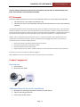
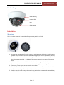
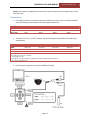
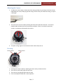
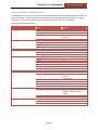
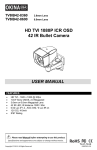
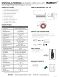
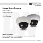
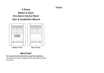
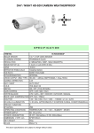
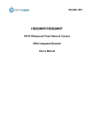
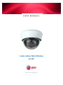
USER MANUAL 3‐Axis Indoor Mini IR Dome ELI‐EDC eLineTechnology.com CAMERA ELI‐EDC USER MANUAL eLineTechnology.com Table of Contents PRODUCT DESCRIPTION ....................................................................................................................... 3 FEATURES ............................................................................................................................................... 3 MODELS................................................................................................................................................. 3 SAFETY INFORMATION ......................................................................................................................... 3 FCC STATEMENT................................................................................................................................... 4 PRODUCT COMPONENTS ..................................................................................................................... 4 BOX CONTENTS ....................................................................................................................................... 4 ADDITIONAL MATERIALS NEEDED FOR INSTALLATION ....................................................................................... 4 PRODUCT DIAGRAMS ................................................................................................................................ 5 INSTALLATION ..................................................................................................................................... 5 MOUNTING ............................................................................................................................................ 5 CONNECTIONS ......................................................................................................................................... 6 ADJUSTING THE CAMERA ........................................................................................................................... 7 FOCUSING .............................................................................................................................................. 7 ON‐SCREEN DISPLAY (OSD) SETTINGS .......................................................................................................... 8 SPECIFICATIONS ................................................................................................................................... 9 TROUBLESHOOTING ............................................................................................................................. 9 WARRANTY REPAIR/REPLACEMENTS ................................................................................................. 10 © 2012 eLine. All rights reserved. eLine provides no warranty with regard to this manual and reserves the right to make any modification to this manual without notice. Page | 2 CAMERA ELI‐EDC USER MANUAL eLineTechnology.com ProductDescription 3‐Axis Indoor Mini IR Dome Congratulations on your purchase of this product. This analog surveillance dome features advanced functions in a compact body and is suited for tight, indoor environments such as a corridor or elevator. The camera utilizes advanced Sony image sensor technology producing high definition, realistic color. Features Indoor plastic mini dome housing Infrared LEDs for night vision 3‐Axis bracket for versatile positioning of the lens On‐Screen Display (OSD) menu controlled by cable button Low Light Illumination, Sense‐UP, Digital Wide Dynamic Range (WDR), 3D Noise Reduction (3DNR) 12V DC Models Model Number ELI‐EDC‐65‐312IR Resolution 650 TVL Lens 2.8~12mm Varifocal Features Infrared SafetyInformation 1. 2. 3. 4. 5. 6. 7. 8. 9. 10. 11. 12. 13. 14. 15. Read these instructions. Heed all warnings. Follow all instructions. Clean only with dry cloth. Do not block any ventilation openings. Do not install near any heat sources such as radiators, heat registers, stoves, or other apparatus including amplifiers) that produce heat. Only use attachments/accessories specified by the manufacturer. Pay attention to the power requirements. Stop operation immediately when something is wrong with the product. If smoke or the smell of smoke comes from the product, continued use will result in fire, injury, or damage to the product. Turn the power off immediately and contact qualified service personnel for service. Be sure to turn off the power before wiring. Failure to observe this may cause electric shock. A short circuit or wrong wiring may cause fire This product has no power switch. Turn the power off when cleaning the product. When continuously viewing a bright light source such as a spotlight, the color filter of the CCD may have deteriorated and it may cause discoloration. Even when changing the fixed viewing direction after continuously viewing a spotlight for a certain period, the discoloration may remain. Keep the camera cable away from the lighting cable. Failure to observe this may cause noise. When the camera is used near a TV/radio antenna, strong electric field, or magnetic field (near a motor or a transformer), images may be distorted and audible noise may be produced. In such a case, route the camera cable through specialized steel conduit tubes. Page | 3 CAMERA ELI‐EDC USER MANUAL eLineTechnology.com CAUTION: TO REDUCE THE RISK OF ELECTRIC SHOCK, DO NOT REMOVE COVER (OR BACK). NO USER SERVICEABLE PARTS INSIDE. REFER SERVICING TO QUALIFIED SERVICE PERSONNEL. FCCStatement THIS DEVICE COMPLIES WITH PART 15 OF THE FCC RULES. OPERATION IS SUBJECT TO THE FOLLOWING TWO CONDITIONS: 1. 2. THIS DEVICE MAY NOT CAUSE HARMFUL INTERFERENCE, AND THIS DEVICE MUST ACCEPT ANY INTERFERENCE RECEIVED, INCLUDING INTERFERENCE THAT MAY CAUSE UNDESIRED OPERATION. This equipment generates and uses radio frequency energy, and if not installed and used properly, that is, in strict accordance with the manufacturer’s instructions, it may cause interference to radio and television reception. It has been type tested and found to comply with the limits for remote control devices in accordance with the specifications in Sub‐Parts B and C of Part 15 of FCC Rules, which are designed to provide reasonable protection against such interference in a residential installation. However, there is no guarantee that interference will not occur in a particular installation. If this equipment does cause interference to radio or television reception, which can be determined by unplugging the equipment, try to correct the interference by one or more of the following measures. Reorient the antenna of the radio/TV experiencing the interference. Relocate the equipment with respect to the radio/TV. Move the equipment away from the radio/TV. Plug the equipment into an outlet on a different electrical circuit from the radio/TV experiencing the interference. If necessary, consult your local dealer for additional suggestions. NOTE: Modifications to this product will void the user’s authority to operate this equipment. ProductComponents BoxContents Dome Camera Quick Start User Guide AdditionalMaterialsNeededforInstallation Minimum of 3 mounting screws and if necessary, drywall anchors Tape for protecting connections Power supply 12VDC 350mA Page | 4 CAMERA ELI‐EDC USER MANUAL eLineTechnology.com ProductDiagrams Plastic Housing Infrared LEDs Lens Plastic Dome Installation Mounting This is an indoor camera. It is not suitable for exposure to particles or liquids. 1. Unscrew the mounting base from the camera by twisting counter‐clockwise. Use this base as a guide to mark the locations for screw and cable management holes on the mounting surface. Make note of the arrow on the base indicating the front of the camera. There are 2 options for the cable management hole – at the back of the camera base or in the center of the camera base. 2. Drill a starter hole at each marked location. Drill a cable management hole at least 14mm in diameter to permit the camera’s cable to be inserted through the mounting surface. 3. If necessary, insert drywall anchors into the screw holes. 4. Place the camera base into location. Insert a screw through each of the screw holes in the base and into the mounting surface and then tighten each screw until the base is secure. 5. Feed the camera’s cable through the access hole; position the dome onto the mounted base, and twist clockwise to secure. Page | 5 CAMERA ELI‐EDC USER MANUAL eLineTechnology.com Caution: Once power is supplied, do not remove the camera from the mounting base due to risk of electrical shock. Connections 1. Use a BNC connector to connect the camera’s VIDEO OUT to the monitor’s (or DVRs) VIDEO IN. Use the following recommendations for cable types and distances: Maximum Cable Length Type of Coaxial Cable Recommended Max Cable Length RG‐59/U 250 M 825 ft RG‐6/U 500 M 1650 ft RG‐11/U 600 M 1980 ft RG‐15/U 800 M 2640 ft 2. The power is DC 12V (+/‐ 10%) / 350mA. Use the following recommendations for cable types and distances: 12V DC Recommended Wire Size and Resistance (68°F) #22 #20 #18 Copper Wire Size #24 2 (0.33 mm2) (0.52 mm2) (0.83 mm2) (AWG) (0.22 mm ) Resistance (Ω/m) 0.078 0.050 0.03 0.018 Resistance (Ω/ft) 0.024 0.015 0.009 0.005 Use the formula below to calculate the power cord and power supply. “L”, “R”, “VA”, “I” shall satisfy the inequality below: 10.8 V DC ≤ VA ‐ 2 (R x I x L) ≤ 16 V DC L = Cord length (m or ft) R = Resistance of copper wire (Ω/m or Ω/ft} VA = DC output voltage of power supply unit I = DC current consumption (A). 3. Connect power supply to the camera’s POWER IN terminal. Page | 6 CAMERA ELI‐EDC USER MANUAL eLineTechnology.com AdjustingtheCamera 1. To adjust the camera angle, remove the white casing and dome by pressing on the latch release indicated by the arrow, and prying off the casing. The first time you remove the casing, it may be a little tight. 2. The camera lens can be moved by twisting the black shell inside the white base. The camera module inside the black shell can be moved up and down. There is no need to remove any screws or to attempt to disassemble the camera. 3. To replace casing, align the arrow with the latch release and press on. Focusing Focus Control Zoom Control 1. 2. 3. 4. Focusing the camera is done by adjusting the two screws just above the lens. The screw on the left will adjust the lens focus. The screw on the right will adjust the lens zoom. Focus to the depth of field that is most important. Page | 7 CAMERA ELI‐EDC USER MANUAL eLineTechnology.com On‐ScreenDisplay(OSD)Settings On the OSD control device on the cable, hit the center button to activate the OSD settings. The menu as below will appear. Use the button by moving up/down/left/right and depressing as ‘Enter’ to change OSD settings. For further definition of each setting see the eLine web site under Support. http://www.elinetechnology.com. Lens ELC DC Exposure HBLC D‐WDR AGC 3D DNR SENSE‐UP BLC HLI/D‐WDR OFF LOW MIDDLE HIGH OFF LOW MIDDLE HIGH AUTO OFF X2 X4 X8 X16 X32 X64 X128 X256 X512 ATW MANUAL AWC>PUSH AWC O‐256 0‐256 AUTO COLOR B&W EXT ON OFF 0‐30 ON(0‐30) OFF ON OFF TOP BOTTOM LEFT RIGHT 0‐30 OFF ICON TRACE 0‐15 Unit: sec ON OFF ON OFF OFF ON: 64 characters OFF MANUAL: WHITE THR 0‐255 BLACK THR 0‐255 DPC LEVEL 0‐255 650 850 CRT LCD 0.45 0.60 1.0 USER 0‐255 PROTOCOL: PELCO‐D BAUDRATE: 2400 4800 9600 bps RETURN CHINESE ENGLISH COLOR DAY & NIGHT FUNCTION MOTION PRIVACY SETUP SYSTEM EXIT EXIT WB MODE R‐Y‐GAIN B‐Y‐GAIN EXIT D&N MODE MIRROR SHARPNESS LSC MOTION AREA SEL. SENSITI DISPLAY HOLD TIME ALARM EXIT MASK1‐MASK8 TITLE DPC OLPF MONITOR GAMA EXIT CAMERA ID COMMUNI LANGUAGE EXIT FACTORY SET SAVE & EXIT EXIT Page | 8 CAMERA ELI‐EDC USER MANUAL eLineTechnology.com Specifications Feature Specification MinimumIllumination S/NRatio ScanningSystem SynchronousSystem AutoElectronicShutter GammaCharacteristic IRDistance VideoOutput AutoGainControl Power/Current Dimension Weight StorageTemperature OperatingTemperature 0.001 Lux / 0 Lux (with IR LED ON) More than 50dB 2:1 Interface Internal, Negative sync NTSC: 1/60s~1/100,000s / PAL: 1/50s~1/100,000s 0.45 20 Meters (with ȼ5x21 pcs Infrared LED) 1Vpp. 75Ω Auto DC 12V (+/‐10%) 350mA ȼ127 x 95(H) mm 520g ‐30°~60°C RH 95% Max ‐10°~45°C RH 95% Max Troubleshooting Nopictureafterprovidingpower Check the power connection to the power supply to the power outlet for connectivity. Check the power supply voltage. Check all connecting cable and monitors for loose connections. Check the monitor settings Thepicturehasinterferenceorripples This may be caused by the power supply’s arc, poor quality cable, too long cable, or improper ground connection. Thepicturebackgroundcolorchangescontinuously A fluorescent light’s electromagnetic field may cause color roll. Reduce the number of fluorescent lights or increase the distance between the camera and the lights to reduce this effect. Use of a power supply with external sync may solve the problem. BlurredImage Check the dome cover for dirt or imperfections Check the focus to make sure adjusted correctly Check the lens of the camera to make sure it is clean. Only use a dry, clean lens cloth to clean the lens. Never touch with your fingers. Page | 9 CAMERA ELI‐EDC USER MANUAL eLineTechnology.com WarrantyRepair/Replacements Subject to the terms of the limited warranty in effect at the time of purchase, e‐Line will repair or replace a product that fails to meet the terms provided, within the product’s warranty period. eLine reserves the right to replace any product under warranty with new, refurbished or remanufactured product. For product purchased directly from eLine by a dealer or an integrator, the warranty period starts from either a) the date of shipment from eLine ’s facility (point of origin) or b) the manufacturer’s date code (if the shipment date is unknown). Except for software products (which shall be treated as if purchased directly e‐Line for purposes of determining the start of the warranty period as set forth in the immediately preceding sentence), for product purchased from an authorized eLine distributor by a dealer or an integrator, the warranty period starts from the date the product is purchased by the dealer or integrator. Warranty periods vary based on product category and type of equipment, as shown in Table 1 entitled “Product Warranty Periods” below. We will return equipment or ship replacement equipment via the same incoming ship method at no additional charge. If you request a different return ship method, we will charge for the full shipping cost. ProductWarrantyPeriods Table 1 lists warranty durations for most eLine equipment, sorted by category. Warranty periods start as set forth under the heading “Warranty Repair/Replacements” above. For items that do not appear in Table 1, contact Customer Service or your sales rep for the applicable policy. Product Type eLine Cloud Cameras Other eLine Product Warranty 2 years 2 years Exceptions PTZ Cameras – 1 year ‐‐‐‐ For help or more information on setup, please visit http://elinetechnology.com Or contact eLine support provided by 2D Electronics at 303.938.1133 [email protected] eLine, 1070 W 124th Ave Suite B‐100, Westminster, CO 80234 Page | 10