1
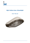
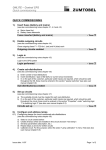
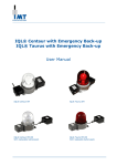
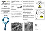
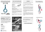
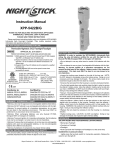
ILED® Aquarius Illuminated Windsock
User Manual
User Manual
ILED® Aquarius Illuminated Windsock
Contents
1.
Safety..................................................................................................................................... 3
2.
Warranty ................................................................................................................................ 3
2.1
2.2
3.
General.................................................................................................................................... 3
Life span .................................................................................................................................. 3
Type plate .............................................................................................................................. 4
3.1
3.2
4.
The light fitting has a type plate: ................................................................................................ 4
The junction box has a type plate: .............................................................................................. 5
Product Description................................................................................................................ 6
5.
Specifications ......................................................................................................................... 7
5.1
5.2
6.
General.................................................................................................................................... 7
Dimensions .............................................................................................................................. 7
Installation ............................................................................................................................ 8
6.1
6.2
6.3
7.
Preparation .............................................................................................................................. 8
Assembly ................................................................................................................................. 8
Connections ............................................................................................................................. 9
Use ....................................................................................................................................... 10
7.1
7.2
7.3
8.
Commissioning ........................................................................................................................10
Switches and Controls ..............................................................................................................10
Insulation test .........................................................................................................................10
Maintenance......................................................................................................................... 10
9.
Recycling.............................................................................................................................. 10
10.
Contact details ..................................................................................................................... 10
11.
EC Declaration of Conformity ............................................................................................... 11
Copyright © IMT B.V.
All rights reserved.
No part of this User Manual may be copied, redistributed, published or changed without the prior written
permission of IMT B.V.
User Manual
ILED® Aquarius Illuminated Windsock
2
Version 1.4 201302
User Manual
ILED® Aquarius Illuminated Windsock
1. Safety
To ensure that the product is used safely and to optimize its life time, the following instructions must be
observed.
Make sure dust layers accumulating on the surface of the enclosure never exceed 5 mm.
Only qualified personnel may install the product.
Observe the locally applicable safety standards and safety regulations.
During assembly, make sure the light fitting is not subjected to mechanical stress.
Use all the mounting holes when installing the light fitting.
Ensure that the cable gland used is certified Ex e IIC Gb and Ex t IIIC Db, and is suitable for the
ambient temperature range and maintain a minimum degree of protection of IP66.
Cables entering the enclosure shall be suitable for use in temperatures of up to at least 81°C.
Ensure that the cable gland used is suitable for the dimensions and type of cable to be connected, to
guarantee the IP degree.
Ensure that the cable gland used has an IP level of IP66, IP67 or IP68 in conformance with EN 60529,
and in case of an explosion proof lighting fixture, is Ex-e certified according to IEC 60079-7.
When using metal glands, use an earthing plate and lock nut on the inside of the junction box.
Ensure there is a reliable connection to the earthing system, both with the external earthing point and
with the connection in the light fitting junction box.
Never open the light fitting's housing.
Do not clean the light fitting with a high-pressure stem or water jet. This will avoid damage that is not
covered by the warranty. Only clean with a damp cloth.
2. Warranty
2.1 General
The warranty for the light fittings in the ILED® Illuminated Windsock series is only valid when the light fitting is
used within the operating limits.
The operating limits are:
The minimum and maximum ambient temperature is -40°C to +55°C.
The light fitting must be installed by qualified personnel according to the installation instructions.
Damage caused by incorrect installation, accidents or external influences, such as a lightning strike or
harmonic distortion not within EN 50055, are not covered by the warranty.
The light fitting's lighting level depends on the temperature and is, therefore, not covered by the warranty.
If an ILED® Aquarius Illuminated Windsock light fitting fails within the warranty period, IMT B.V. will provide a
new light fitting with similar specifications free of charge. Before it can be confirmed that the damage is
covered by the warranty, the defective light fitting must be sent to IMT B.V. at the user’s expense for
inspection. The user will be informed of the result(s) of the inspection. For individual warranty agreements see
invoice.
The windsock itself (the fabric) is not covered by warranty.
2.2 Life span
Switching the light fitting with a semiconductor photoelectric cell or semiconductor relay has no consequences
for the life span of the light fitting. Allowing a light fitting to ‘flash’ that is adjusted standard as a steady
burning light fitting, by means of a semiconductor photoelectric cell or semiconductor relay has, however, a
negative effect on the life time.
User Manual
ILED® Aquarius Illuminated Windsock
3
Version 1.4 201302
User Manual
ILED® Aquarius Illuminated Windsock
3. Type plate
3.1 The light fitting has a type plate:
1.
Type
: ILED Aquarius
2.
Version
: Windsock
: Obstruction light
: Type X
3.
Ambient temp..
: -40°C tot +55°C
4.
Serial number
5.
Year of production
6.
Forward LED voltage : Max 48Vdc
7.
LED Current
: Windsock
: Obstruction
8.
Power
: Windsock
: Obstruction
9.
Marking
: EX e IIC T4 Gb
: Ex tb IIIC T135°C Db
56mm
81mm
I_max=450mA
I_max = 450 or 700mA
max 22W
max 34W
Attention.
The current and power consumption depends on the purpose of the light fitting .
For this reason the indicated values in the table can be different, but never more
than the maximum value.
Attention.
Above mentioned information concerns the light fitting. For connections of the
driver see label on driver.
User Manual
ILED® Aquarius Illuminated Windsock
4
Version 1.4 201302
User Manual
ILED® Aquarius Illuminated Windsock
3.2 The junction box has a type plate:
1.
Type
:
:
:
:
ILED
ILED
ILED
ILED
ULD35W
ULD35W
ULD35W
ULD35W
DC IN GRP JB
AC IN GRP JB
DC IN SS JB
AC IN SS JB
2.
Serial number
:
3.
Year of production
:
4.
Voltage
: DC: 24Vdc±10%
: AC: 90-250Vac
5.
Current
: DC: Max 2.34A
: AC: Max 0.49A
6.
Power
: Max 40W
7.
Pros. Short-Cut Current
: 200A
8.
Ambient temp..
: -40°C tot +55°C
9.
Marking
: EX e mb IIC T4 Gb
: Ex tb IIIC T135°C Db IP66
Attention.
The current and power consumption depends on the purpose of the light fitting .
For this reason the indicated values in the table can be different, but never more
than the maximum value.
User Manual
ILED® Aquarius Illuminated Windsock
5
Version 1.4 201302
User Manual
ILED® Aquarius Illuminated Windsock
4. Product Description
All ILED® Aquarius Illuminated Windsock light fittings are designed for use in demanding surroundings.
Features of the ILED® Aquarius Illuminated Windsock light fittings:
High quality materials
Sealed for life
Vibration-proof.
Based on ILED® technology.
User Manual
ILED® Aquarius Illuminated Windsock
6
Version 1.4 201302
User Manual
ILED® Aquarius Illuminated Windsock
5. Specifications
5.1 General
Construction
: Stainless steel 316L (AISI)
Construction light fitting
: Marine grade aluminum anodized
Lens
: Borosilicate glass
Illumination color Windsock
: White
Illumination color obstruction light : Red according to ICAO Annex 14 Vol. 1 Appendix 1
Illumination color U-code
: Red according to ICAO Annex 14 Vol. 1 Appendix 1
Mechanical protection
: IP66
Voltage, external driver
: 95-250Vac 50/60Hz or 24Vdc ±10%
Burning position
: Horizontal
(Re)ignition
: Instant
Power factor
: >0,9
Connection
: Fitted as standard with junction box, suitable for a single-phase connection
Options
The following options are available for all ILED® Illuminated Windsock light fittings:
Base Pole
Top Pole with Top Light /Obstruction Light
LAN network connection
Spare sock
5.2 Dimensions
User Manual
ILED® Aquarius Illuminated Windsock
7
Version 1.4 201302
User Manual
ILED® Aquarius Illuminated Windsock
6. Installation
6.1 Preparation
1.
Check whether the light fitting is to be installed in an environment that meets the ambient temperatures,
gas group and temperature class. This data is included on the light fitting type plate.
WARNING
Installation of a light fitting in an environment that does not meet the specified
ambient temperatures may have a negative effect on the life time of the light
fitting.
2.
Choose the correct type of protection for the light fitting. When doing so, ensure:
a. The choice of cut-off current for the safety device is suitable for the expected nominal current.
This depends on the number of light fittings that are connected.
b. The safety device's cut-off power is suitable for the maximum short-circuit current that the mains
power supply can provide.
6.2 Assembly
1.
2.
Remove the light fitting from the packaging.
Inspect the light fitting for mechanical damage.
WARNING
Installation of a light fitting in an environment that does not meet the specified
ambient temperatures may have a negative effect on the life time of the light
fitting.
3.
4.
5.
Mount the light fitting to the construction.
Ensure a reliable connection to the earthing system, both with the external earthing point and with the
connection in the light fitting junction box.
Take precautions to prevent corroding of the earth connection, to ensure its functionality.
Ensure that the cable glands used are suitable for the dimensions and type of cable to be connected, to
guarantee the IP class, and in case of an explosion proof lighting fixture the glands are Ex certified as
follows: Ex e IIC T4 Gb and Ex tb IIIC T135C Db IP66 ( Atex II 2 GD) by IEC 60079-0:2007 Ed5, IEC
60079-7 Ed 4, IEC 60079-31:2008 Ed 1.
The chosen gland for the fixture has a thread of M12 x 1.5mm. This gland is already provided with the
cable of type Jobarco PUR flex TPE guaranteed up to at least 81 °C by your manufacturer.
WARNING
Clean fixture only with damp cloth.
6.
7.
8.
Assemble the various components according to the drawing in 5.2 and always use all available assembly
holes.
Pull the sock over the sock holder so that the rim of the sock is over the round protuberance. (locking ring)
Assemble the quick strainer by sliding it over the sock from the front and lock it with the locking bolt.
User Manual
ILED® Aquarius Illuminated Windsock
8
Version 1.4 201302
User Manual
ILED® Aquarius Illuminated Windsock
9.
The mounting plate with junction box can be mounted either with the junction box upwards, or
downwards.
WARNING
During assembly, make sure the light fitting is not subjected to mechanical stress.
10. Cable glands and plugs shall be installed according to the instructions of the manufacturer, and shall not
invalidate the specific characteristics of the type of protection of the electrical equipment on which they are
mounted.
The cable entries for the junction box are plane holes suitable for glands size M20 x 1.5 or M25 x 1.5.
The cable glands for the junction box should be chosen in accordance to the selected cable, to ensure
a guarantee of insulation of the gland and preventing the cable of transmitting pulling or twisting
forces to the terminals in the junction box.
Plugs, intended to close unused openings in the junction box, shall satisfy the required protection and
IP class, and shall only be mounted or removed with the aid of a tool.
Cable glands and blanking plugs may only be tightened or released during installation with proper
tools and forces as indicated by the manufacturer.
Cables shall be stripped according to the instructions of the manufacturer with the appropriate tools
to guarantee the functional properties of the cable and IP degree.
A wire sleeve shall be positioned to the bare wire ends suitable for the quadratic wire diameter and
placed with a specified tool according to the instructions of the manufacturer.
11. Connect the cable to the terminals.
The standard connecting terminals are suitable for a core diameter of 0.5-4 mm².
Terminals shall be installed and tightened with appropriate tools according to the installation
instructions of the manufacturer. The placement and assembly will be done in such a way that the
degree of protection and safety of the device is guaranteed.
12. Check the completed connections.
13. Close the junction box.
6.3 Connections
The terminal block design depends on the product type purchased.
In the junction box is a standard terminal block as illustrated below:
The following connections can be made
L, N and PE
1 and 2
3 and 4
5 and 6
:
:
:
:
Connection for the power (For 24Vdc version L = + and N = -)
Connection : DC output 1 ( LED current source)
Connection : DC output 2 ( LED current source)
Option : Connection for local network ( LAN)
Warning
Swapping
Swapping
Swapping
Swapping
over
over
over
over
+ and – can damage the luminary
1 and 2 can damage the luminary
3 and 4 can damage the luminary
5 and 6 can damage the luminary
WARNING
If metal cable glands or blind plugs are used, an earthing plate must be used in the
junction box.
User Manual
ILED® Aquarius Illuminated Windsock
9
Version 1.4 201302
User Manual
ILED® Aquarius Illuminated Windsock
7. Use
7.1 Commissioning
The light fitting can be used as soon as the installation has been completed.
WARNING
Obtaining a flash function by switching the supply voltage has a strongly negative
effect on the life span.
7.2 Switches and Controls
The light fitting can be equipped with a communication connection (option : see “connections”). It is possible to
set several factory settings using special software.
For switching on, off and controlling the light fitting there is a control unit available (IMT-LED-MASTER). This
control unit is connected with the communication connections in the light fitting.
7.3 Insulation test
Installations in which ILED® Illuminated Windsock light fittings are mounted may be tested with an insulation
test.
For this test, apply a maximum of 500 Vdc between earth and phase or neutral, or between the earth and the
plus and minus of the 24Vdc version together, or between the earth and both of the network connections
together.
WARNING
Never apply 500Vdc between phase and neutral, or between the plus and minus of
the led fixture or between the network connections themselves.
All light fittings have undergone a dielectric test during production (24Vdc version: 700Vdc during 60 seconds,
Multi voltage version: 2100 Vdc during 60 seconds). In addition, the light fittings have also been subjected to
an endurance test.
8. Maintenance
The light fittings are `sealed for life’ and therefore cannot be opened. Because of this maintenance, as defined
in the IEC 60079-17 standard, is not applicable and visual inspection only for correct functioning is sufficient.
WARNING
Opening the light fitting voids all claims under guarantee.
Only clean with a damp cloth.
9. Recycling
Agreements have been made with local authorities for the recycling of the light fittings within the framework of
the WEEE (Waste Electrical and Electronic Equipment Directive)
We refer to your local partner (see 'Contact details'). The local partner will take care of further disposal
10.
Contact details
IMT B.V.
Pascalweg 10a, 4104 BG Culemborg
P.O. Box 88, 4100 AB Culemborg
THE NETHERLANDS
Phone : +31 (0)88 – 12 69 100
Fax
: +31 (0)88 – 12 69 101
E-mail : [email protected]
For an up-to-date overview of all national and international contacts, visit our website: www.imt.eu.
User Manual
ILED® Aquarius Illuminated Windsock
10
Version 1.4 201302
User Manual
ILED® Aquarius Illuminated Windsock
11.
EC Declaration of Conformity
The undersigned, representing the company
IMT B.V.
Pascalweg 10a
4104 BG Culemborg
The Netherlands
Phone :+31 (0) 88 - 12 69 100
declares that the product: ILED ® Aquarius Illuminated Windsock and Obstruction luminaires, type
IMT-LED Windsock, Obstruction, U-Code marked with Ex II 2 GD Ex e IIC T4 Gb or Ex II 2 GD Ex tb IIIC
T135°C Db complies with the provisions of the EC directive(s) - including all supplements.
94/9/EC
Equipment and protective systems intended for use in potentially explosive atmospheres
2004/108/EC
Electromagnetic Compatibility
and that provisions have been made in all standards and/or technically related specifications below.
Standard
Issue
EN 60079-0
2009
EN 60079-7
2007
EN 60079-31
2009
EN 61547
2009
EN 61000-3-2
2006
Title
Electrical apparatus for potentially explosive atmospheres
General requirements
Electrical apparatus for potentially explosive atmospheres
Increased safety “e”
Explosive atmospheres – Part 31: Equipment dust ignition protection by enclosure
“t”
Equipment for general lighting purposes. EMC immunity requirements
Limits for harmonic current emissions (equipment input current up to and including
EC type certificate number :
16A per phase),
IECEx SIR 11.0046X
Sira 11ATEX3101X
Culemborg, 20 juni 2011
IMT B.V.
R.L.L.M.G. Mignot , Managing director
User Manual
ILED® Aquarius Illuminated Windsock
11
Version 1.4 201302
IMT B.V.
Pascalweg 10a, 4104 BG Culemborg
P.O. Box 88, 4100 AB Culemborg
Tel: +31 (0)88 – 12 69 100, Fax +31 (0) 88 – 12 69 101
www.imt.eu, [email protected]