1
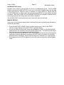
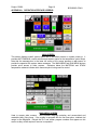
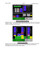
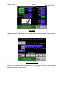
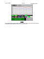
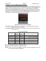
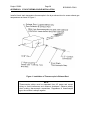
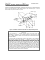
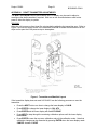
Project: R3930
Page 6
BCS6000C-CSA-9
MOTOR CALIBRATION & SETUP Screen
Press the MAIN MENU key to access the menu screen, then press the MOTOR CALIBRATION
& SETUP button to display the calibration screen.
MOTOR CALIBRATION
The control motor DEADBAND settings determine the allowable deviation (+/-) of actual
control motor position from setpoint without corrective action by the motor control
outputs (minimum 0.2%, maximum 2.5%, typically set at 0.5% for fuel and 0.8% for air).
These parameters should be set as low as possible without causing the control motors
to ‘hunt’ excessively. Touch the numeric displays and use the popup keypad to enter a
deadband setting for each motor.
Press the ZERO button to drive all control motors closed for calibration and record the
slidewire feedback signals. Confirm that all motors have reached their low fire positions
before beginning span calibration.
Press the SPAN button to drive the motors open and record the resulting feedback
signals. Verify that all motors have fully opened before pressing the OFF button to store
the span values and end motor calibration.
BURNER OPERATING PARAMETERS
Set the BURNER OUTPUT LIMIT at 100.0% for normal operation. This value may need
to be lowered to accommodate system limitations.
Enter a LOW FIRE AIR percentage if applicable. The burner will lightoff with the air
motor at zero and then drive open to the low fire setting to minimize blower surge.
The LIGHTOFF TIME setting determines how long the air and fuel valves will remain in
their lightoff positions before returning to their low fire settings. Timing begins as soon
as the main fuel valve has opened.
If the optional gas flow display and totalizer are installed, set the GAS PRESSURE to
match the pressure, in osig, measured just upstream of the gas orifice flange assembly.
TEMPERATURE DISPLAY
If the Material and Stack temperatures displayed on the touchscreen are significantly
different from the UDC120L instrument displays, a positive or negative BIAS value may
be entered for each instrument.
CONTROL LOOP TUNING Screen
After setting and recording all parameters on the Motor Calibration & Setup screen, press MAIN
MENU key to return to the menu screen then select the CONTROL LOOP TUNING button to
display the loop tuning screen. This screen is used to enter tuning constants for each of the
three PID control loops. MATERIAL or STACK temperature control may also be selected on
this screen. Manual control of the burner firing rate and exhaust damper control motors are also
provided.
Enter a GAIN setting for each loop. Note that Gain = 100/Proportional Band% or
Proportional Band% = 100/Gain. For example, a Gain of 2 is equivalent to a
Proportional Band setting of 50%. Note that the range of the PID control loops in the
BCS6000 is 1000.
Enter a DEADBAND setting (°F for temperature and "WC for draft) for each loop. This
value should be as small as possible without excessive ‘hunting’ by the control
actuators.
Enter a RESET setting for the Material and Stack control loops. Note that Reset is
expressed in minutes per repeat rather than repeats per minute. Therefore, the smaller
the setting the more frequently reset action will be repeated.