1
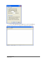
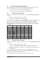
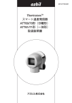
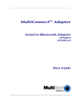
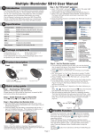
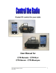
5913 AT Command Appendix CONTROL MICROSYSTEMS SCADA products... for the distance 48 Steacie Drive Kanata, Ontario K2K 2A9 Canada Telephone: 613-591-1943 Facsimile: 613-591-1022 Technical Support: 888-226-6876 888-2CONTROL 5913 AT Command Appendix ©2007 Control Microsystems Inc. All rights reserved. Printed in Canada. Trademarks TeleSAFE, TelePACE, SmartWIRE, SCADAPack, TeleSAFE Micro16 and TeleBUS are registered trademarks of Control Microsystems Inc. All other product names are copyright and registered trademarks or trade names of their respective owners. 5913 AT Command Appendix November 21, 2007 1 Table of Contents 1 USING AT COMMANDS ................................................................................ 4 1.1 Using Windows HyperTerminal ................................................................ 4 1.2 1.2.1 1.2.2 Serial Port Communication Parameters ................................................... 8 Read the Serial Port Settings .............................................................. 8 Write the Serial Port Settings .............................................................. 8 1.3 1.3.1 1.3.2 1.3.3 1.3.4 Setting Security......................................................................................... 9 Turn on 5913 Security ....................................................................... 10 Software Reset 5913 ......................................................................... 10 Change 5913 PIN .............................................................................. 10 Important Security Notes ................................................................... 10 2 AT COMMANDS .......................................................................................... 11 2.1 At Command Format .............................................................................. 11 2.2 Attention (AT) Command Prefix .............................................................. 11 2.3 Get 5913 Firmware Version Command .................................................. 11 2.4 5913 Reset Commands .......................................................................... 12 2.5 Get 5913 Status Information ................................................................... 13 2.6 Set and Read 5913 Boot Mode .............................................................. 19 2.7 Set and Read 5913 Security Level ......................................................... 20 2.8 Set and Read Maximum Number of Bluetooth Connections .................. 21 2.9 Set and Read 5913 Name ...................................................................... 22 2.10 Set and Read Service Name for Local and Remote Devices ................. 22 2.11 Set and Read Security PIN Settings ....................................................... 24 2.12 Set Class of Device (COD) ..................................................................... 27 2.13 Write 5913 Configuration Commands .................................................... 27 2.14 Read 5913 Configuration ........................................................................ 35 2.15 Inquiry Command ................................................................................... 35 2.16 Connect as Master.................................................................................. 36 2.17 Set Master Default Bluetooth Address.................................................... 40 2.18 Connect as Slave.................................................................................... 41 2.19 Disconnect .............................................................................................. 42 5913 AT Command Appendix November 21, 2007 2 2.20 Command and Data Modes .................................................................... 42 2.21 Cancel Command ................................................................................... 44 2.22 Pairing Commands ................................................................................. 44 2.23 2.23.1 3.7.3 Sniff and Park (Connected Slave) ................................................. 46 Low Power Modes Using Sniff .......................................................... 46 2.24 RSSI and Link Quality............................................................................. 50 2.25 Audio (SCO) PCM Interface ................................................................... 52 2.26 Max TX Power ........................................................................................ 52 2.27 Link Supervisory Timeout ....................................................................... 53 2.28 Variable Storage ..................................................................................... 54 2.29 Transmitting on a Specific Channel Only ................................................ 54 2.30 Making the 5913 Discoverable and Undiscoverable ............................... 55 3 AT COMMAND SUMMARY TABLE ............................................................ 56 4 5913 FACTORY DEFAULT SETTINGS ...................................................... 60 5 ACRONYMS/ABBREVIATIONS .................................................................. 62 6 MAINTENANCE ........................................................................................... 63 5913 AT Command Appendix November 21, 2007 3 1 Using AT Commands The 5913 is shipped with factory default setting. These settings are shown in section 4 5913 Factory Default Settings. These settings can be modified to suit your application preferences. The 5913 powers up into an unconnected state and will respond to inquiry and connection requests. Then, just like controlling a modem, the host or client can issue AT commands which map to various Bluetooth activities. The command set is extensive enough to allow a host to make connections which are authenticated and encrypted or not. The 5913 is configured through simple ASCII strings over a remote Bluetooth RF connection. AT commands are sent from the host 5914 to the 5913 over the Bluetooth connection. The 5913 needs to be connected to a serial port on a SCADAPack controller and the 5914 needs to be connected to the host PC. 1.1 Using Windows HyperTerminal The Windows program HyperTerminal is a terminal program that can be used to send AT commands to the 5913 from the host PC. This section of the user manual describes how to set up a terminal session using HyperTerminal. To Start HyperTerminal: Start >> All Programs >> Accessories >> Communications >> HyperTerminal. When HyperTerminal is started you will see the following dialog. A name for the connection can be entered if desired. Click OK once you are finished with this dialog. 5913 AT Command Appendix November 21, 2007 4 The next dialog to appear sets the serial communication port on your PC to use when communicating with the 5913. The communication port Com40 is the typical default port, as seen in the 5914 installation. One you have selected the serial port click OK. The next dialog is the properties dialog which sets the port settings. Set the Port Settings as shown above. These are the default settings that the 5913 is shipped with. Click OK when finished. The connection dialog now closes but there is one further setting that needs to be made. From the File menu select Properties. The following dialog will appear. 5913 AT Command Appendix November 21, 2007 5 Click the Settings tab. The following page appears. Click the ASCII Setup button to open the ASCII Setup dialog. 5913 AT Command Appendix November 21, 2007 6 Select the Echo typed characters locally check box and click the OK button. The HyperTerminal session is now configured for communication with the 5913. 5913 AT Command Appendix November 21, 2007 7 1.2 Serial Port Communication Parameters The serial port on the 5913 module is set for 9600 baud, 8 data bits, no parity and 1 stop bit at the factory. These setting may be viewed or changed using the following commands: To read the serial port (UART) settings use the ATSI,8 command. To change the serial port (UART) settings use the ATSW20 command. 1.2.1 Read the Serial Port Settings Connect to the 5913 module using HyperTerminal (see section 1.1 Using Windows HyperTerminal for details). Enable the Command mode by entering +++ <CR>. Enter the command ATSI,8 <CR> Get UART Settings. The reply for the 5913 will be OK followed by 0027,000,000 when the 5913 is in the default factory condition. This somewhat cryptic response represents <baud rate>, <parity>, <stop bits> When reading the UART settings the values are in HEX format. The following table shows the actual values for baud rate, parity and number of stop bits based on the HEX values returned from the ATSI,8 command. <baud rate> 0005 000A 0014 0027 004F 009D 00EC 01D8 03B0 075F 0EBF 1.2.2 <parity> 1200 2400 4800 9600 19,200 38,400 57,600 115,200 230,400 460,800 921,600 0000 0001 0002 <stop bits> None Odd Even 0000 0001 1 2 Write the Serial Port Settings Connect to the 5913 module using HyperTerminal (see section 1.1- Using Windows HyperTerminal for details). Enable the Command mode by entering +++<CR>. Enter the command ATSW20, <Baudrate>,<Parity>,<Stop Bits>,<Store><CR> Note that this command does not return OK. The serial settings may be confirmed using the ATSI,8 command. The factory default setting of 9600,8,n,0 would be entered as ATSW20,39,0,0,1. The store parameter will save the setting to flash when set to 1. When the parameters are saved in flash they will be retained when power is removed from the 5913. The serial parameters are entered as ASCII values as described in the table below. 5913 AT Command Appendix November 21, 2007 8 Note: Serial port settings are read as HEX values and entered as ASCII values. <baud rate> 0 5 20 39 79 157 236 472 944 1887 3775 1.3 <parity> 1200 2400 4800 9600 19,200 38,400 57,600 115,200 230,400 460,800 921,600 0 1 2 <stop bits> None Odd Even 1 2 <Store> 1 2 0 1 Do not store Store in flash Setting Security In many cases it is desirable to ensure a secure link between the 5913 and the 5914. This is achieved using the Personal Identification Number (PIN) of the 5913. When the 5913 is configured for security and another Bluetooth device attempts to make a connection it will be prompted for the 5913 PIN. By default security on the 5913 is disabled at the factory. If you do not need a secure connection you can skip this section of the user manual. The 5913 will respond to queries from the 5914 and establish a link with it without enabling security. Note on PIN Security: The 5913 and the 5914 provide authentication and encryption using the Bluetooth standard. A 10 to 16-character PIN provides excellent protection against attacks on the PIN; known attacks rely on a short PIN (4 numbers in many devices) to succeed quickly. The longer PIN protects against this attack. The known attack can crack a 4-digit PIN in 0.06 seconds on a Pentium IV 3GHz HT computer. This attack relies on cycling through the 10^4 = 10000 possible values for the PIN. A 10-character PIN utilizing upper and lower case characters and digits provides 62^10 = 839,299,365,868,340,224 possibilities. This will take approximately 160,000 years on the same computer. There are a number of AT commands that control the security settings and PIN in the 5913. See section 2.11 Set and Read Security PIN Settings. The order for setting the PIN and using it when a link is established is as follows: Turn on 5913 security using command SW24. Reset the 5913 using a software reset command URST. Set the PIN from the factory default value of default to a 10 character PIN of your own choosing using command ATSP. These AT commands are described in the following sections. 5913 AT Command Appendix November 21, 2007 9 1.3.1 Turn on 5913 Security Connect to the 5913 module using HyperTerminal (see section 1.1 Using Windows HyperTerminal for details). Enable the Command mode by entering +++ <CR>. The command SW24 Write Response, Security, Auto SCO, Filter Settings is used to enable 5913 Bluetooth security. Enter the command ATSW24,0,1,0,0<CR> to turn on security. The second parameter turns security on or off, a value of 1 will turn security on and a value of 0 will turn security off. See section 2.13 Write 5913 Configuration Commands for complete details on the ATSW24command. Use command ATSI,6 to read the security settings. 1.3.2 Software Reset 5913 Once the security is turned on the 5913 Bluetooth needs to be reset for the change to take place. Connect to the 5913 module using HyperTerminal (see section 1.1 Using Windows HyperTerminal for details). Enable the Command mode by entering +++ <CR>. Enter the command ATURST<CR> to perform a software reset on the 5913. See section 2.4 5913 Reset Commands for complete details on the ATURST command. 1.3.3 Change 5913 PIN By default the 5913 PIN is set to default. This can be changed to any 10 character PIN using the ATSP command. Connect to the 5913 module using HyperTerminal (see section 1.1 Using Windows HyperTerminal for details). Enable the Command mode by entering +++ <CR>. Enter the command ATSP,<newPIN>,<oldPIN><CR>. The <newPIN> data is any 10 character sequence. The <oldPIN> data is the current PIN in the 5913. See section 2.11 Set and Read Security PIN Settings for complete details on the ATSP command. 1.3.4 Important Security Notes A factory reset does NOT reset the PIN. So you have to be very careful with typing the PIN. A factory reset does reset the security enable setting. So if you forget the PIN it is only possible to use the device without security settings. The 5913 remembers a previous connection, i.e. if you connect successfully with correct authentication, the PIN isn‟t asked for again in the next connection attempt. It is possible to “unpair” all connections on the 5913 using command ATCPAIR<CR>. This will ensure that a PIN will be requested on the next connection. 5913 AT Command Appendix November 21, 2007 10 2 AT Commands The 5913 is configured, commanded, and controlled through simple ASCII strings over a remote Bluetooth RF connection. The host (PC) issues AT commands which map to various Bluetooth activities. The command set is extensive enough to allow a host to make connections which are authenticated and encrypted or not. NOTE: The complete list of AT commands is presented in this section of the manual. These commands are divided into sections to make navigating the list easier. For most users most of these commands are not needed. 2.1 At Command Format All commands are typed exactly as shown in the examples for each command. <cr> = <0x0d carriage return> <cr_lf> = <0x0d carriage return> <0x0a linefeed> All commands are entered in the following format: “COMMAND”<cr>. Valid commands respond with a <cr_lf>OK<cr_lf> or <cr_lf>ERROR<cr_lf>. Only exceptions are ATSW20 and ATURST which do not reply. All replied data after the command response has the following format <cr,lf>data<cr,lf>. HEX vs. Decimal – When writing or entering integer AT Command string values enter them in Decimal format. When reading values from memory they will be returned in Hexadecimal format. 2.2 AT Attention (AT) Command Prefix AT PREFIX Function: The prefix AT must precede every valid command except for “+++”. The remainder of the command script contains commands for the radio. The command script must end with a carriage return. EXAMPLE: TYPE : AT<cr> REPLY: <cr_lf>OK<cr_lf> Note: AT Commands can be upper or lower case. The only exception is the radios Personal Identification alphanumeric Number (PIN) is caps sensitive, and ATOP. 2.3 VER Get 5913 Firmware Version Command GET MODULE FIRMWARE VERSION Function: Gets the radio‟s firmware version. Format: ATVER,ver1 Return Parameters: <Firmware Version> 5913 AT Command Appendix November 21, 2007 11 EXAMPLE: TYPE : ATVER,ver1<cr> REPLY: <cr_lf>OK<cr_lf> <cr_lf>Ver 3.5.2.1.4.0<cr_lf> Notes: 2.4 URST „„ver1‟‟ is case sensitive, be sure to enter it in lower case. Make sure the radio version number matches this document version before proceeding. 5913 Reset Commands RESET Function: Tells the radio to perform software reset on the CPU. Format: ATURST EXAMPLE: TYPE : ATURST<cr> REPLY: None Notes: FRST This unique Command does not reply with “OK” or “ERROR” because of internal UART data processing limitations and response timing. You can send the reset command over the Bluetooth RF connection. FACTORY RESET Function: Resets the radio back to factory defaults. Format: ATFRST EXAMPLE: TYPE : ATFRST<cr> REPLY: <cr_lf>OK<cr_lf> <cr_lf>RESET COMPLETE<cr_lf> OR <cr_lf>ERROR<cr_lf> Note: You can send the factory reset command over the Bluetooth RF connection. SSW,0 SET BYPASS FOR HARDWARE FACTORY CONFIGURATION RESET PUSHBUTTON Function: Use this command to prevent an inadvertent factory configuration reset. 5913 AT Command Appendix November 21, 2007 12 Format: ATSSW,0,<Enable/Disable> Parameters: Enable/Disable: 0 = factory reset enabled 1 = factory reset disabled EXAMPLE: TYPE : ATSSW,0,1<cr> REPLY: <cr_lf>OK<cr_lf> OR <cr_lf>ERROR<cr_lf> Read Using: ATRSW,0 RSW,0 READ BYPASS FOR HARDWARE FACTORY CONFIGURATION RESET PUSHBUTTON Function: Reads the factory reset enable/disable register state. Format: ATRSW,0 Return Parameters: <Enable/Disable> EXAMPLE: TYPE : ATRSW,0<cr> REPLY: <cr_lf>OK<cr_lf> <cr_lf>00<cr_lf> Set Using: ATSSW,0 2.5 Get 5913 Status Information Status Information can be obtained directly from the Bluetooth Radio. This information is important when managing a connection list of devices in a local area and the current settings of the radio. SI STATUS INFORMATION Function: Gets specified status information from the LOCAL radio. Format: ATSI,<Status Request> Parameters: Status Request: Integer 0 – 22 Note: If the Set Using field is listed, see the listed AT command for more info on return parameters. 0 GET MODULE TYPE 5913 AT Command Appendix November 21, 2007 13 Return Parameters: <Module Type> EXAMPLE: TYPE : ATSI,0<cr> REPLY: <cr_lf>OK<cr_lf> <cr_lf>BlueRadios ATMP<cr_lf> 1 GET BT ADDRESS Return Parameters: <BT Address> EXAMPLE: TYPE : ATSI,1<cr> REPLY: <cr_lf>OK<cr_lf> <cr_lf>123456789012<cr_lf> 2 GET FRIENDLY NAME Set Using: ATSN Return Parameters: <Friendly Name> EXAMPLE: TYPE : ATSI,2<cr> REPLY: <cr_lf>OK<cr_lf> <cr_lf> BlueRadios <cr_lf> 3 GET CURRENT CONNECTION STATUS (CH00-CH03) Return Parameters: <Connection Status> Connection Status: Single Connection Format: (Mode, Ch00 State) MP Format: (Mode,Ch00 State,Ch01 State,Ch02 State,Ch03 State) Repeater Format: (Mode,Slave-Ch00 State,Master-Ch01 State) Modes: 0 = Slave, 1 = Auto-Master, 2 = Idle, 3 = Slave Undiscoverable, 5 = Repeater, 6 = Mesh States: 0 = Disconnected, 1 = Connected EXAMPLE: TYPE : ATSI,3<cr> REPLY: <cr_lf>OK<cr_lf> <cr_lf>1,0,0,0,0<cr_lf> Note: This command does not report the status of any FTP or OPP connections, use ATSI,22 to obtain FTP/OPP status. 4 GET SERVICE NAME 5913 AT Command Appendix November 21, 2007 14 Set Using: ATSSN Return Parameters: <Service Name> EXAMPLE: TYPE : ATSI,4<cr> REPLY: <cr_lf>OK<cr_lf> <cr_lf>COM0<cr_lf> 5 GET CLASS OF DEVICE (COD) Set Using: ATSC Return Parameters: <COD> EXAMPLE: TYPE : ATSI,5<cr> REPLY: <cr_lf>OK<cr_lf> <cr_lf>00000000<cr_lf> 6 GET RESPONSE, SECURITY, AUTO SCO, FILTER SETTINGS Set Using: ATSW24 Return Parameters: <Response Type>,<Security>,<Auto SCO>,<Minor Filter> EXAMPLE: TYPE : ATSI,6<cr> REPLY: <cr_lf>OK<cr_lf> <cr_lf>0,0,0,0<cr_lf> 7 GET CONNECTION, COMM, UNCONNECTED UART, DEFAULT SERVICE MODES Set Using: ATSW25 Return Parameters: <Power-Up Connection Mode>,<Comm Mode>, <Unconnected UART Mode>,<Default Service> EXAMPLE: TYPE : ATSI,7<cr> REPLY: <cr_lf>OK<cr_lf> <cr_lf>0,1,0,0<cr_lf> 8 GET UART SETTINGS Set Using: ATSW20 Return Parameters: <Baudrate>,<Parity>,<Stop Bits> (HEX) EXAMPLE: TYPE : ATSI,8<cr> 5913 AT Command Appendix November 21, 2007 15 REPLY: <cr_lf>OK<cr_lf> <cr_lf>0027,0000,0000<cr_lf> 9 GET MASTER AUTO-CONNECT ADDRESS Set Using: ATSMA Return Parameters: <BT Address>,<UUID> EXAMPLE: TYPE : ATSI,9<cr> REPLY: <cr_lf>OK<cr_lf> <cr_lf>Not Set!<cr_lf> OR <cr_lf>OK<cr_lf> <cr_lf>123456789012,1101<cr_lf> 10 GET SLAVE SCAN INTERVALS AND WINDOWS Set Using: ATSW21 Return Parameters: <psInterval>,<psWindow>,<isInterval>,<isWindow> (HEX) EXAMPLE: TYPE : ATSI,10<cr> REPLY: <cr_lf>OK<cr_lf> <cr_lf>0400,0200,0400,0200<cr_lf> 11 GET PIO(5) PULSE RATE Set Using: ATSW27 Return Parameters: <Pulse Period [ms]> (HEX) EXAMPLE: TYPE : ATSI,11<cr> REPLY: <cr_lf>OK<cr_lf> <cr_lf>03E8<cr_lf> 12 GET ESCAPE CHARACTER Set Using: ATSESC Return Parameters: <ASCII Char> (HEX) EXAMPLE: TYPE : ATSI,12<cr> REPLY: <cr_lf>OK<cr_lf> <cr_lf>2B<cr_lf> 5913 AT Command Appendix November 21, 2007 16 13 GET INQUIRY AND MASTER CONNECT TIMEOUT SETTINGS Set Using: ATSW28 Return Parameters: <Inquiry Timeout>,<Master Connect Request Timeout> (HEX) EXAMPLE: TYPE : ATSI,13<cr> REPLY: <cr_lf>OK<cr_lf> <cr_lf>0010,0028<cr_lf> 14 GET MAX TX POWER LEVEL Set Using: ATSPF Return Parameters: +/-<Power Level> (HEX) EXAMPLE: TYPE : ATSI,14<cr> REPLY: <cr_lf>OK<cr_lf> <cr_lf>default<cr_lf> OR REPLY: <cr_lf>OK<cr_lf> <cr_lf>+0A<cr_lf> 15 GET PIN LOCK MODE Set Using: ATSW29 Return Parameters: <Lock Mode> (HEX) EXAMPLE: TYPE : ATSI,15<cr> REPLY: <cr_lf>OK<cr_lf> <cr_lf>00<cr_lf> 16 GET DEEP SLEEP MODE Set Using: ATSW30 Return Parameters: <Deep Sleep Mode> (HEX) EXAMPLE: TYPE : ATSI,16<cr> REPLY: <cr_lf>OK<cr_lf> <cr_lf>00<cr_lf> 17 GET SNIFF SETTINGS Set Using: ATSSNIFF 5913 AT Command Appendix November 21, 2007 17 Return Parameters: <Max Interval>,<MinInterval>,<Attempt>,<Timeout> (HEX) EXAMPLE: TYPE : ATSI,17<cr> REPLY: <cr_lf>OK<cr_lf> <cr_lf>Not Set!<cr_lf> OR <cr_lf>OK<cr_lf> <cr_lf>0000,0000,0000,0000<cr_lf> 18 GET LINK SUPERVISORY TIMEOUT Set Using: ATLSTO Return Parameters: <Time> (HEX) EXAMPLE: TYPE : ATSI,18<cr> REPLY: <cr_lf>OK<cr_lf> <cr_lf>04<cr_lf> 19 GET LIST OF PAIRED OR SECURED ADDRESSES Set Using: ATPAIR Return Parameters: Index,<BT Address> (HEX) EXAMPLE: TYPE : ATSI,19<cr> REPLY: <cr_lf>OK<cr_lf> 00,<cr_lf> 01,<cr_lf> 02,<cr_lf> 03,<cr_lf> Note: 00 – 03 Are for indexing the stored addresses only, they do not indicate that the address is associated with any specific channel. 20 GET CHANNEL UUIDS Set Using: ATSSNC Return Parameters: <Ch00 UUID>,<Ch01 UUID>,<Ch02 UUID>,<Ch03 UID> (UUIDs for Ch01-03 will only be returned if enabled using ATSSW3) EXAMPLE: TYPE : ATSI,20<cr> 5913 AT Command Appendix November 21, 2007 18 REPLY: <cr_lf>OK<cr_lf> <cr_lf>1101<cr_lf> //Point to point OR <cr_lf>1101,1101,1101<cr_lf> //Multipoint with 3 channels 21 GET SPECIFIC TRANSMISSION CHANNEL Set Using: ATSWC Return Parameters: <Selected>,<Channel> EXAMPLE: TYPE : ATSI,21<cr> REPLY: <cr_lf>OK<cr_lf> <cr_lf>01,03<cr_lf> 22 GET FTP/OPP CONNECTION STATUS Return Parameters: <Connection Status> Connection Status: 0 = Disconnected, 1 = Connected EXAMPLE: TYPE : ATSI,22<cr> REPLY: <cr_lf>OK<cr_lf> <cr_lf>1<cr_lf> 2.6 SSW,1 Set and Read 5913 Boot Mode SET BOOT MODE Function: Sets the boot mode. Format: ATSSW,1,<Boot Mode> Parameters: Boot Mode: 0 = VM Mode // Default baud rate = 9600, 8-N-1 1 = HCI Mode // Fixed baud rate = 115.2k, 8-N-1 2 = BCSP Mode // Fixed baud rate = 115.2k, 8-N-1 Factory Default: VM Mode EXAMPLE: TYPE : ATSSW,1,1<cr> REPLY: <cr_lf>OK<cr_lf> OR 5913 AT Command Appendix November 21, 2007 19 <cr_lf>ERROR<cr_lf> Read Using: ATRSW,1 Note: All AT Commands work only with the VM. RSW,1 READ BOOT MODE Function: Gets the boot mode. Format: ATRSW,1 Return Parameters: <Boot Mode> EXAMPLE: TYPE : ATRSW,1<cr> REPLY: <cr_lf>OK<cr_lf> <cr_lf>00<cr_lf> Set Using: ATSSW,1 2.7 SSW,2 Set and Read 5913 Security Level SET SECURITY LEVEL Function: Sets the Security Level register state. Format: ATSSW,2,<Security Level> Parameters: Security Modes: 0 = Link Level – Highest level of security. 1 = Service Level – Provides service information without using PIN. Factory Default: VM Mode EXAMPLE: TYPE : ATSSW,2,1<cr> REPLY: <cr_lf>OK<cr_lf> OR <cr_lf>ERROR<cr_lf> Read Using: ATRSW,2 RSW,2 SECURITY LEVEL Function: Gets the Security level register state. Format: ATRSW,2 Return Parameters: <Boot Mode> 5913 AT Command Appendix November 21, 2007 20 EXAMPLE: TYPE : ATRSW,2<cr> REPLY: <cr_lf>OK<cr_lf> <cr_lf>00<cr_lf> Set Using: ATSSW,2 2.8 SSW,3 Set and Read Maximum Number of Bluetooth Connections SET MAX CONNECTION NUMBER Function: Sets the maximum number of Bluetooth connections. Enables multipoint mode if number of connections is greater than one. Format: ATSSW,3,<Number of Connections> Parameters: Number of Connections: Integer Value 1-4 Factory Default: 1 EXAMPLE: TYPE : ATSSW,3,1<cr> REPLY: <cr_lf>OK<cr_lf> Notes: RSW,3 Fast Data Mode is only supported with 1 connection and ##,00 packet header is never sent. It is recommended you limit the number of connections for your application to maximize performance and security. Requires a reset for change to take affect. By default data is broadcast to all connected radios when the local radio is in data mode. The radio can be set to transmit to a specific channel using the ATSWC command. (See the Utilities section for more information). READ MAX CONNECTION NUMBER Function: Reads the maximum number of Bluetooth connections. Format: ATRSW,3 Return Parameters: <Max Connections> EXAMPLE: TYPE : ATRSW,3<cr> REPLY: <cr_lf>OK<cr_lf> <cr_lf>01<cr_lf> 5913 AT Command Appendix November 21, 2007 21 2.9 Set and Read 5913 Name When another Bluetooth Radio performs a discovery, this will be the name that is passed to that radio. Please take note, unlike the name, the 5913 Bluetooth address is fixed (48bit) at the factory and is unique to every Bluetooth device manufactured. SN SET RADIO NAME Function: Sets the local radio‟s friendly name. Format: ATSN,<Name> Parameters: Name: 16 alphanumeric characters MAX Factory Default: BlueRadio EXAMPLE: TYPE : ATSN,MYRADIOS_0123456<cr> REPLY: <cr_lf>OK<cr_lf> OR <cr_lf>ERROR<cr_lf> Read Using: ATSI,2 RRN READ REMOTE RADIO NAME BY BLUETOOTH ADDRESS Function: Gets a remote radio‟s friendly name using its Bluetooth address. Format: ATRRN,<BT Address> Parameters: BT Address: Bluetooth Address, 12 hex characters MAX Return Parameters: <Radio Name> EXAMPLE: TYPE : ATRRN,0123456789012<cr> REPLY: <cr_lf>OK<cr_lf> <cr_lf>Bluetooth<cr_lf> OR <cr_lf>NO ANSWER<cr_lf> Note: The timeout for this command is controlled by the master connect timeout in ATSW28. 2.10 SSN Set and Read Service Name for Local and Remote Devices SET SERVICE NAME 5913 AT Command Appendix November 21, 2007 22 Function: Sets the Bluetooth Service Name of channel 0 on the local device. Format: ATSSN,<Service Name> Parameters: Service Name: 16 alphanumeric characters MAX Factory Default: “COM0” EXAMPLE: TYPE : ATSSN,COM0<cr> REPLY: <cr_lf>OK<cr_lf> OR <cr_lf>ERROR<cr_lf> Read Using: ATSI,4 or ATRSN Note: Requires a reset for change to take affect. SSNC SET SERVICE NAME BY CHANNEL Function: Sets the local Bluetooth Service Name and Service UUID by channel number. Format: ATSSNC,<Channel Number>,<Service Name>,<UUID> Parameters: Channel Number: 0, 1, 2, 3 Service Name: 16 alphanumeric characters MAX UUID: 4 digit, binary profile code (See Appendix C for more info) Factory Default: “COM0” for Channel 0, “COM1” for Channel 1, “COM2” for Channel 2, “COM3” for Channel 3 EXAMPLE: TYPE : ATSSNC,0,My Device,1101<cr> REPLY: <cr_lf>OK<cr_lf> OR <cr_lf>ERROR<cr_lf> Note: Requires a reset for change to take affect. RSN READ SERVICE NAME Function: Reads the local Bluetooth Service Name. Format: ATRSN Return Parameters: <Service Name> EXAMPLE: TYPE : ATRSN<cr> 5913 AT Command Appendix November 21, 2007 23 REPLY: <cr_lf>OK<cr_lf> <cr_lf>COM0<cr_lf> RSNC READ SERVICE NAME BY CHANNEL Function: Reads the local Bluetooth Service Name by channel number. Format: ATRSNC,<Channel Number> Parameters: Channel Number: 0-3 Return Parameters: <Service Name> EXAMPLE: TYPE : ATRSNC,0<cr> REPLY: <cr_lf>OK<cr_lf> <cr_lf>COM0<cr_lf> RRSN READ REMOTE SERVICE NAME Function: Reads a remote Bluetooth device Service Name and Service Channel Number for a specific profile. Format: ATRRSN,<BT Address>,<UUID> Parameters: BT Address: Bluetooth Address, 12 hex characters MAX UUID: 4 digit, binary profile code (See Appendix C for more info) Return Parameters: <Service Channel Number>,<Service Name> EXAMPLE: TYPE : ATRRSN,123456789012,1101<cr> REPLY: <cr_lf>OK<cr_lf> <cr_lf>01,Bluetooth Serial Port<cr_lf> <cr_lf>02,Bluetooth Serial Port (2)<cr_lf> OR <cr_lf>NO ANSWER<cr_lf> Note: The timeout for this command is controlled by the master connect timeout in ATSW28. 2.11 SSW,6 Set and Read Security PIN Settings SET PIN REQUEST HANDLING MODE Function: Sets the PIN (Personal Identification Number) request handling mode. If set to 5913 AT Command Appendix November 21, 2007 24 0 the PIN stored using the ATSP command will automatically be used during PIN exchanges. If set to 1 the prompt “PIN REQUEST” will be output by the radio and the user will need to manually enter a PIN using the ATPR command. Format: ATSSW,6,<Mode> Parameters: Mode: 0 = Automatic PIN Request Handling 1 = Manual PIN Request Handling Factory Default: 0 EXAMPLE: TYPE : ATSSW,6,1<cr> REPLY: <cr_lf>OK<cr_lf> OR <cr_lf>ERROR<cr_lf> Read Using: ATRSW,6 Note: Requires a reset for change to take affect. RSW,6 READ PIN REQUEST HANDLING MODE Function: Reads the PIN request handling mode. Format: ATRSW,6 Return Parameters: <Mode> EXAMPLE: TYPE : ATRSW,6<cr> REPLY: <cr_lf>OK<cr_lf> <cr_lf>00<cr_lf> Set Using: ATSSW,6 SP SET PIN Function: Sets the PIN to be used with automatic PIN request handling. **Warning** Be careful when entering a new PIN. There is no way to obtain PIN status after it is changed. If the PIN is changed after two units have already authenticated and connected you will have perform a software or hardware reset for the devices to use the new PIN‟s if not the two units will still connect using the old stored PIN. Format: ATSP,<New PIN>,<Old PIN> Parameters: New PIN: 16 alphanumeric characters MAX (Caps Sensitive, includes spaces) 5913 AT Command Appendix November 21, 2007 25 Old PIN: 16 alphanumeric characters MAX (Caps Sensitive, includes spaces) Factory Default: default EXAMPLE: TYPE : ATSP,1234567890123456,default<cr> REPLY: <cr_lf>OK<cr_lf> OR <cr_lf>ERROR<cr_lf> Note: If security is enabled in multipoint mode, all connected slaves will have to use the same PIN. There is no way to assign an individual PIN to each slave. OP OVERWRITE PIN Function: Overwrites the stored PIN without needing the old PIN. To use this command the PIN must be unlocked using ATSW29. Format: ATOP,<PIN> Parameters: PIN: 16 alphanumeric characters MAX (Caps Sensitive, includes spaces) EXAMPLE: TYPE : ATOP,1234<cr> REPLY: <cr_lf>OK<cr_lf> OR <cr_lf>ERROR<cr_lf> //If ATOP has not been enabled with ATSW29 ATPR RESPOND TO MANUAL PIN REQUEST Function: Allows the user to manually enter a PIN after receiving the PIN REQUEST prompt from the radio. Format: ATPR,<PIN> Parameters: PIN: 16 alphanumeric characters MAX (Caps Sensitive, includes spaces) EXAMPLE: REPLY: <cr_lf>PIN REQUEST<cr_lf> TYPE : ATPR,default<cr> REPLY: <cr_lf>OK<cr_lf> OR <cr_lf>ERROR<cr_lf> 5913 AT Command Appendix November 21, 2007 26 2.12 SC Set Class of Device (COD) SET COD Function: Sets the COD. Format: ATSC,<COD> Parameters: COD: Exactly 8, 16-bit hex values (0 thru F) based on the Bluetooth COD specification names published and maintained by the Bluetooth SIG. Factory Default: 00000000 – Which is undefined since this is set by the user based on the final OEM device it is installed in. EXAMPLE: TYPE : ATSC,00020114<cr> REPLY: <cr_lf>OK<cr_lf> OR <cr_lf>ERROR<cr_lf> Read Using: ATSI,5 Note: 2.13 Requires a reset for change to take affect. Write 5913 Configuration Commands S registers refer to memory locations used for configuration. The SW commands are used to assign values to various registers in the radio‟s flash memory that are stored in nonvolatile memory SW20 WRITE UART (Serial Port) SETTINGS Function: Configures UART settings. Format: ATSW20,<Baudrate>,<Parity>,<Stop Bits>,<Store> Parameters: Baudrate: 1200 – 921.6Kbps, enter ASCII Value from table below. **Contact BlueRadios for calculating and setting custom baud rates not listed in the table. As long as the equation BAUDRATE *0.004096 produces an integer value, then there will be 0% error in clocking for the baud rate. Baud r at e ASCII Value Er r or No Change 1200 2400 4800 9600 19.2k 38.4k 57.6k 0 5 10 20 39 79 157 236 5913 AT Command Appendix November 21, 2007 1.73% 1.73% 1.73% -0.82% 0.45% -0.18% 0.03% 27 115.2k 230.4k 460.8k 921.6k 472 944 1887 3775 0.03% 0.03% -0.02% 0.00% Parity: 0 = None 1 = Odd 2 = Even Stop Bits: 0 = One 1 = Two Store Parameters: 0 = Do Not Store 1 = Store Parameters in Flash Factory Default: Baudrate = 39, Parity = 0, Stop Bits = 0 (8, N, 1 w/ hardware flow control RTS/CTS enabled) EXAMPLE: TYPE : ATSW20,39,0,0,1<cr> // 9600 8,N,1 store in flash REPLY: This unique Command does not reply with “OK” or “ERROR” because of internal UART data processing limitations and response timing. Read Using: ATSI,8 Notes: SW21 Flow control is always enabled, short CTS/RTS together if not used. The RTS line of the radio will be low when the radio is ready to receive data and high when its buffer is full. When RTS goes high wait until it returns to low before sending more data to avoid losing information. To reconfigure radio back to default factory settings apply 3.3vdc on PIO#4 during initial power up for > 2sec. WRITE SLAVE SCAN INTERVALS AND WINDOWS **Warning** Setting these will affect the inquiry and connection time. You could inadvertently set the scan interval too long and the window to short on the slave for a master connect request. Unless your application is battery powered slave and power conservation is critical leave at the factory default settings. The minimum Window allowed by the Bluetooth spec is 11.25msec. If you set isWindow = 0 the Slave device will not be discovered by any Master but you can still use the Slaves BT address and connect directly to it from a remote Master. Function: Configures Page Scan and Inquiry Scan Interval and Window for disconnected slave devices in time slots. Format: ATSW21,<psInterval>,<psWindow>,<isInterval>,<isWindow> 5913 AT Command Appendix November 21, 2007 28 Parameters: psInterval: Page Scan Interval Integer Value 18 to 4096 (11.25ms to 2560ms), 0=Disabled Time [ms] = psInterval * 0.625ms psWindow: Page Scan Window Integer Value 18 to 4096 (11.25ms to 2560ms), 0=Disabled Time [ms] = psWindow * 0.625ms isInterval: Inquiry Scan Interval Integer Value 18 to 4096 (11.25ms to 2560ms), 0=Disabled Time [ms] = isInterval * 0.625ms isWindow: Inquiry Scan Window Integer Value 18 to 4096 (11.25ms to 2560ms), 0=Disabled Time [ms] = isWindow * 0.625ms Factory Default: psInterval = 1024(640ms), psWindow = 512(320ms), isInterval = 1024(640ms), isWindow = 512(320ms) EXAMPLE: TYPE : ATSW21,4096,18,4096,18<cr> REPLY: <cr_lf>OK<cr_lf> OR <cr_lf>ERROR<cr_lf> Read Using: ATSI,10 Notes: Requires a reset for the settings to go into affect. ATSW21,4096,18,4096,18 settings will result in a current draw for an unconnected slave of ~ 1mA average vs. 39mA average at default. ATSW21,4096,18,4096,18 settings along with enabling Deep Sleep Mode will result in an unconnected slave current draw of ≈350uA average. SW22 This S Register is not used. SW23 This S Register is not used. SW24 WRITE RESPONSE, SECURITY, AUTO SCO, FILTER SETTINGS Function: Configures response, security, auto sco, and filter settings. Format: ATSW24,<Response Type>,<Security>,<Auto SCO>,<Minor Filter> Parameters: Response Type: 0 = Long Response 5913 AT Command Appendix November 21, 2007 29 1 = Short Response 2 = No Verbose Mode (No unsolicited responses will be output) - No OKs will come back, but requested information such as ATSI, ATRSW, ATRSN and ATDI responses will. - The radio will not output CONNECT or DISCONNECT messages. - In FTP and OPP modes the radio will still output all necessary messages such as PUSH START and PUSH COMPLETE. *Security: 56bit encryption is automatically enabled when set to 1. UART will reply PAIRED,<BT Address> before the CONNECT,<BT Address> is returned when a connection is made. 0 = No Authorization 1 = Authorization Required Auto SCO: 0 = No Automatic SCO Connect 1 = SCO Auto Connect Upon Radio Connect. **Minor Filter: 0 = Disable Minor COD Filter on Inquiry 1 = Enable Minor COD Filter on Inquiry Factory Default: Response Type = 0, Security = 0, Auto SCO = 0, Filter = 0 EXAMPLE: TYPE : ATSW24,0,0,0,0<cr> REPLY: <cr_lf>OK<cr_lf> OR <cr_lf>ERROR<cr_lf> Read Using: ATSI,6 Notes: SW25 See Appendix B for differences between short response and long response mode. Requires a reset for security to go into affect. *If security is enabled in multipoint mode, all connected slaves will have to use the same PIN. There is no way to assign an individual PIN to each slave. **With the minor filter enabled, inquiry results are filtered by the lower 2 bytes of the COD. If the minor filter is disabled all devices are found. WRITE CONNECTION, COMM, UNCONNECTED UART, DEFAULT SERVICE MODES **Warning** The only way to communicate to the radio after setting the radio in “Fast Data Mode” and “ignore UART while unconnected” is to apply 3.3Vdc on PIO(4) during initial power up for >2 sec. These settings are used if you have no control over the source of streaming data into the radio, or you do not know when the radio has made a Bluetooth 5913 AT Command Appendix November 21, 2007 30 connection, and do not plan on sending any AT commands. Function: Configures connection, comm, unconnected UART and default service modes. Format: ATSW25,<Power-Up Connection Mode>,<Comm Mode>,<Unconnected UART Mode>, <Default Service Profile> Parameters: Power-Up Connection Mode: 0 = Slave 1 = Auto-Master (Set ATSMA Command First)* 2 = Idle Mode** 3 = Slave Undiscoverable 5 = Repeater (Set ATSMA Command First)*** 6 = Mesh Configuration 7 = OPP Server (See FTP and OPP Modes Section for more info) 8 = FTP Server (See FTP and OPP Modes Section for more info) Comm Mode: 0 = Fast Data**** 1 = Data 2 = Command Unconnected UART Mode: 0 = Allow Data to Pass While Unconnected 1 = Ignore Data While Unconnected Default Service Profile: This field has no longer has any effect, it can just be set to 0. Service profile UUIDs are now set using the ATSSNC command. Factory Default: Connection Mode = 0, Comm Mode = 1, Unconnected UART Mode = 0, Default Service Profile = 0 EXAMPLE: TYPE : ATSW25,0,1,0,0<cr> //Slave radio connects in fast data mode REPLY: <cr_lf>OK<cr_lf> OR <cr_lf>ERROR<cr_lf> Read Using: ATSI,7 Notes: Requires a reset for the settings to go into affect. *Auto-Connect Master always connects using the highest available channel. If none available it will continue to retry. **In idle mode the radio is neither slave nor master and draws 1.6mA of current but you can not communicate over the Bluetooth link in this state only through the TX & RX hardware UART. 5913 AT Command Appendix November 21, 2007 31 SW26 ***Repeater always uses channel 00 for slave and 01 for Master. ****If data mode is set to „„Fast Data Mode‟‟ in a Master unit during a manual inquiry „„ATDI‟‟ and/or connection request the radio connects in slow data mode not fast. This is because you will need the capability to issue commands because in fast data mode the AT command parser is turned off. The comm mode parameter has no effect when operating in FTP or OPP mode. LOCK USER SETTINGS **Warning** This command will lock the PIN. Function: Locks user settings to prevent unauthorized local & remote access. Format: ATSW26,<PIN>,<Lock/Unlock> Parameters: PIN: 16 alphanumeric characters MAX (Caps Sensitive, includes spaces) Lock/Unlock: 0 = Unlocked 1 = Locked Factory Default: Unlocked EXAMPLE: TYPE : ATSW26,default,1<cr> REPLY: <cr_lf>OK<cr_lf> OR <cr_lf>ERROR<cr_lf> Note: ATSW26 will still work after locking the user settings, allowing them to be unlocked. SW27 WRITE LED RATE Function: Sets the LED Pulse Rate on PIO(5). Format: ATSW27,<Pulse Period> Parameters: Pulse Rate: Integer decimal value from 1ms to 60,000ms Factory Default: 1000 EXAMPLE: TYPE : ATSW27,1000<cr> //1000 ms REPLY: <cr_lf>OK<cr_lf> OR <cr_lf>ERROR<cr_lf> 5913 AT Command Appendix November 21, 2007 32 Read Using: ATSI,11 Note: Used to indicate slave mode operation and inquiry in process. Duty cycle equals 50%. SW28 WRITE INQUIRY AND MASTER TIMEOUT SETTINGS Function: Configures inquiry and master connect timeout settings. Format: ATSW28,<Inquiry Timeout>,<Master Connect Request Timeout> Parameters: Inquiry Timeout: Integer value from 1 to 40 [seconds] Master Connect Request Timeout: Integer value from 1 to 40 [seconds] Factory Default: Inquiry Timeout = 16, Master Connect Request Timeout = 40 EXAMPLE: TYPE : ATSW28,16,40<cr> // factory default REPLY: <cr_lf>OK<cr_lf> OR <cr_lf>ERROR<cr_lf> Read Using: ATSI,13 Notes: SW29 Due to a CSR bug, this command will accept values up to 40, but the actual timeouts will never go over approximately 22 seconds. The master connect request timeout also controls the timeouts on the ATRRN, ATRRSN and ATPAIR commands. WRITE PIN LOCK MODE Function: Configures PIN lock setting. Format: ATSW29,<PIN>,<Lock Mode> Parameters: PIN: 16 alphanumeric characters MAX (Caps Sensitive, includes spaces) Lock Setting: 0 = In Normal operation ATOP is disabled 1 = Allow ATOP through UART only 2 = Allow ATOP through UART and over RF Link Factory Default: 0 EXAMPLE: TYPE : ATSW29,default,1<cr> REPLY: <cr_lf>OK<cr_lf> 5913 AT Command Appendix November 21, 2007 33 OR <cr_lf>ERROR<cr_lf> Read Using: ATSI,15 Note: This command enables ATOP, described in the Security PIN Settings section. SW30 WRITE DEEP SLEEP MODE Function: Configures deep sleep mode. Format: ATSW30,<Deep Sleep Mode> Parameters: Deep Sleep Mode: 0 = Normal Operation never go into deep sleep 1 = Go into deep sleep whenever possible (While idle, page scan or sniff mode) Factory Default: 0 EXAMPLE: TYPE : ATSW30,1<cr> REPLY: <cr_lf>OK<cr_lf> OR <cr_lf>ERROR<cr_lf> Read Using: ATSI,16 Notes: When the radio is in deep sleep you can not discover or connect to it. The UART RX line needs to be pulled high if not active before power is applied to the radio module. If there is an active UART RF link the device will need Sniff Mode enabled to allow it to drop into sleep mode when there is no traffic. When in deep sleep, the UART will miss the first character while waking up. Send a preamble byte to allow it to wake up and immediately thereafter send the AT Command or data in less than 1 second or the device will go back to deep sleep again. No bytes are lost if sending commands down over the remote RF link side. This setting is stored in flash and does not require a reset to take affect. Takes approx. 1 second before the current will drop down to 25- 50uA. Allow 5msec. for the CPU unit to come out of deep sleep. ATSW21,4096,18,4096,18 settings along with enabling Deep Sleep Mode will result in an unconnected slave current draw of ≈350uA average. . 5913 AT Command Appendix November 21, 2007 34 2.14 Read 5913 Configuration S registers refer to memory locations used for configuration. The SR commands are used to read values from various registers in the radio‟s Flash Memory that are stored in nonvolatile memory. SR21 READ PIO LEVEL Function: Reads PIO logic level. Format: ATSR21,<PIO#> Parameters: PIO#: 2-7 Return Parameters: <Logic Level> EXAMPLE: TYPE : ATSR21,3<cr> REPLY: <cr_lf>OK<cr_lf> <cr_lf>1<cr_lf> Set Using: ATSW23 2.15 Inquiry Command The inquiry command is used to discover all Bluetooth radios (within range) that match a certain Class of Device (COD). If the COD is not known it is best to use 00000000 which allows discovery of all devices. You can not be in the default slave mode and perform an inquiry command. Only a Master or a Radio in idle mode can perform an inquiry. DI INQUIRE Function: Inquire Command. Used to discover other Bluetooth devices. Format: ATDI,<Max Radios to Discover>,<COD> Parameters: Max Radios to Discover: 0-60,000 *COD: Exactly 8, 16-bit hex values (0 thru F) based on the Bluetooth COD specification names published and maintained by the Bluetooth SIG. Return Parameters: <BT Address>,<COD> (Repeated by number of radios found) An “OK” is returned immediately following this command. “DONE” will appear after all devices have been found, or an inquiry timeout has occurred while searching for the number of devices specified. EXAMPLE MASTER: TYPE : ATDI,1,00000000<cr> REPLY: <cr_lf>OK<cr_lf> <cr_lf>00A0961F2023,00000000<cr_lf> 5913 AT Command Appendix November 21, 2007 35 <cr_lf>DONE<cr_lf> OR <cr_lf>ERROR<cr_lf> Notes: IL Recommend executing an ATUCL command to put the radio in idle mode prior to executing an Inquiry command. See Utilities section. Due to a CSR bug, there is no guarantee that the radios returned by an inquiry will all be unique – duplicates can occur. This seems to happen if the inquiry doesn‟t discover the maximum number of radios. After discovering all of the radios it can, it will then start to return duplicate radios that it has already discovered until the maximum is reached or the inquiry times out. *With the minor filter enabled using ATSW24, inquiry results are filtered by the lower 4 bytes of the COD. If the minor filter is disabled all devices are found. The request for friendly name is a separate message request in the new CSR firmware --- see ATRRN. LAST INQUIRY Function: Repeats last inquiry. Format: ATIL Return Parameters: <BT Address>,<COD> An “OK” is returned immediately following this command. “DONE” will appear after all devices have been found, or an inquiry timeout has occurred while searching for the number of devices specified. EXAMPLE MASTER: TYPE : ATIL<cr> REPLY: <cr_lf>OK<cr_lf> <cr_lf>00A0961F2023,00000000<cr_lf> <cr_lf>DONE<cr_lf> OR <cr_lf>ERROR<cr_lf> Note: ATDI command string previously used is stored in flash memory. 2.16 Connect as Master This command is used to connect one 5913 radio module to another. Doing this will enable data transmission bidirectionally. When performing this command the reply is critical so as to understand where the connection process is. A connection can take several seconds, so when making a connection, if it is not already connected, an “OK” will be sent back immediately. Don‟t mistake this for a connection being complete. A completed connection will return “CONNECT,00,123456789012” some time after the command was sent typically less than 2 5913 AT Command Appendix November 21, 2007 36 seconds. The blue LED on the 5913 will turn on and stay on while a Bluetooth connection is established on Channel connection 00. Note: If either the slave or the master of the connection issues a disconnect command the 5913 will output “DISCONNECT.” If a connection is lost unexpectedly then “LINKLOSS” will be output. DM DIAL AS MASTER Function: This command creates a connection using the Slave‟s address and UUID profile code. Format: ATDM,<BT Address>,<UUID> Parameters: BT Address: Bluetooth Address, 12 hex characters MAX UUID: 4 digit, binary profile code (See Appendix C for more info) Return Parameters: <BT Address> or <Channel Number><BT Address> POINT TO POINT EXAMPLE: TYPE : ATDM,123456789012,1101<cr> REPLY: <cr_lf>OK<cr_lf> <cr_lf>CONNECT,123456789012<cr_lf> OR <cr_lf>OK<cr_lf> <cr_lf>PAIRED,123456789012<cr_lf> // if security is enabled <cr_lf>CONNECT,123456789012<cr_lf> OR <cr_lf>NO ANSWER<cr_lf> // if device not present MULTIPOINT EXAMPLE: TYPE : ATDM,123456789012,1101<cr> REPLY: <cr_lf>OK<cr_lf> <cr_lf>CONNECT,00,123456789012<cr_lf> OR <cr_lf>OK<cr_lf> <cr_lf>PAIRED,123456789012<cr_lf> // if security is enabled <cr_lf>CONNECT,00,123456789012<cr_lf> OR <cr_lf>NO ANSWER<cr_lf> // if device not present Notes: 5913 AT Command Appendix November 21, 2007 37 DC If the remote Slave device is not present or the service is not available, NO ANSWER will reply after the master connect timeout and you will have to try again. If security is enabled and the radio is connecting to a PC that has not yet been paired with it, the <cr_lf>PAIRED,12345678912<cr_lf> message may return twice prior to the CONNECT. By using the ATDC command connection time will be decreased to approximately 500ms. DIAL CHANNEL Function: Connects to a remote device by Bluetooth address and service channel number (RF Comm ID). This will decrease the connection time to approximately 500ms. Format: ATDC,<BT Address>,<Service Channel Number> Parameters: BT Address: Bluetooth Address, 12 hex characters MAX Remote Service Channel#: 0-3 Return Parameters: <BT Address> or <Channel Number><BT Address> POINT TO POINT EXAMPLE: TYPE : ATDC,123456789012,1<cr> REPLY: <cr_lf>OK<cr_lf> <cr_lf>CONNECT,123456789012<cr_lf> OR <cr_lf>OK<cr_lf> <cr_lf>PAIRED,123456789012<cr_lf> // if security is enabled <cr_lf>CONNECT,123456789012<cr_lf> OR <cr_lf>NO ANSWER<cr_lf> // if device not present MULTIPOINT EXAMPLE: TYPE : ATDC,123456789012,1<cr> REPLY: <cr_lf>OK<cr_lf> <cr_lf>CONNECT,00,123456789012<cr_lf> OR <cr_lf>OK<cr_lf> <cr_lf>PAIRED, 123456789012<cr_lf> // if security is enabled <cr_lf>CONNECT,00,123456789012<cr_lf> OR 5913 AT Command Appendix November 21, 2007 38 <cr_lf>NO ANSWER<cr_lf> // if device not present Notes: DL Use the ATRRSN command to get a remote service channel number from another device. If the remote Slave device is not present or the service is not available, NO ANSWER will reply after the master connect timeout and you will have to try again. If security is enabled and the radio is connecting to a PC that has not yet been paired with it, the <cr_lf>PAIRED,12345678912<cr_lf> message may return twice prior to the CONNECT. DIAL LAST Function: Connects to last successful Slave Bluetooth address connection over SPP unless ATDM command was executed then the UUID from the ATDM command will be used. Format: ATDL Return Parameters: <BT Address> or <Channel Number><BT Address> POINT TO POINT EXAMPLE: TYPE : ATDL REPLY: <cr_lf>OK<cr_lf> <cr_lf>CONNECT,123456789012<cr_lf> OR <cr_lf>OK<cr_lf> <cr_lf>PAIRED,123456789012<cr_lf> // if security is enabled <cr_lf>CONNECT,123456789012<cr_lf> OR <cr_lf>OK<cr_lf> <cr_lf>NO ANSWER<cr_lf> // if device not present OR <cr_lf>ERROR<cr_lf> MULTIPOINT EXAMPLE: TYPE : ATDL REPLY: <cr_lf>OK<cr_lf> <cr_lf>CONNECT,00,123456789012<cr_lf> OR <cr_lf>OK<cr_lf> <cr_lf>PAIRED,123456789012<cr_lf> // if security is enabled 5913 AT Command Appendix November 21, 2007 39 <cr_lf>CONNECT,123456789012<cr_lf> OR <cr_lf>OK<cr_lf> <cr_lf>NO ANSWER<cr_lf> // if device not present OR <cr_lf>ERROR<cr_lf> Notes: LAST To verify the stored address use the ATLAST command below. If the remote Slave device is not present or the service is not available, NO ANSWER will reply after the master connect timeout and you will have to try again. If security is enabled and the radio is connecting to a PC that has not yet been paired with it, the <cr_lf>PAIRED,12345678912<cr_lf> message may return twice prior to the CONNECT. READ LAST ADDDRESS Function: Gets the last connected Bluetooth device address. Format: ATLAST Return Parameters: <BT Address> EXAMPLE: TYPE : ATLAST<cr> REPLY: <cr_lf>OK<cr_lf> <cr_lf>000000000000<cr_lf> // Nothing stored OR <cr_lf>OK<cr_lf> <cr_lf>123456789012<cr_lf> // Last connected BT address 2.17 SMA Set Master Default Bluetooth Address SET MASTER DEFAULT ADDRESS Function: This command will set a specific Bluetooth Slave address and service profile into the Master device so on power up the Master will automatically search and connect to a unique Slave device on the highest available channel. Format: ATSMA,<BT Address>,<UUID> Parameters: BT Address: Bluetooth Address, 12 hex characters MAX 5913 AT Command Appendix November 21, 2007 40 UUID: 4 digit, binary profile code (See Appendix C for more info) EXAMPLE: TYPE : ATSMA,00A0961F904F,1101<cr> REPLY: <cr_lf>OK<cr_lf> OR <cr_lf>ERROR<cr_lf> Read Using: ATSI,9 Notes: MACLR Execute ATSW25 to set the power up connect mode to auto-master before using the above command if still in slave mode. This command is limited to only one connection. Reset module for change to take affect. MASTER ADDRESS CLEAR Function: Clears stored slave address. Format: ATMACLR EXAMPLE: TYPE : ATMACLR<cr> REPLY: <cr_lf>OK<cr_lf> OR <cr_lf>ERROR<cr_lf> 2.18 Connect as Slave Not e : If either the slave or the master of the connection issues a disconnect command the radio will output “DISCONNECT.” If a connection is lost unexpectedly then “LINKLOSS” will be output. DS DIAL AS SLAVE Function: This command places the Radio in Slave mode where it waits for a connection to occur from a Master. Format: ATDS Return Parameter: OK EXAMPLE SLAVE: TYPE : ATDS<cr> REPLY: <cr_lf>OK<cr_lf> 5913 AT Command Appendix November 21, 2007 41 2.19 DH Disconnect DIAL HANG UP Function: This command will disconnect the current connection on channel 0. Format: ATDH EXAMPLE: TYPE : ATDH<cr> REPLY: <cr_lf>OK<cr_lf> <cr_lf>DISCONNECT<cr_lf> OR <cr_lf>ERROR<cr_lf> Notes: DHC If you send this command over the RF link to a remote BlueRadios Slave the Slave will disconnect and go into Idle mode not Slave mode by design. If a connection should unexpectedly be lost the response will be <cr_lf>LINKLOSS<cr_lf> instead of <cr_lf>DISCONNECT<cr_lf>. DIAL HANG UP BY CHANNEL Function: This command will issue disconnect to the specified channel. Format: ATDHC,<Channel Number> EXAMPLE: TYPE : ATDHC,00<cr> REPLY: <cr_lf>OK<cr_lf> <cr_lf>DISCONNECT,00<cr_lf> OR <cr_lf>ERROR<cr_lf> Notes: 2.20 +++ If you send this command over the RF link to a remote BlueRadios Slave the Slave will disconnect and go into Idle mode not Slave mode by design. If a connection should unexpectedly be lost the response will be <cr_lf>LINKLOSS,00<cr_lf> instead of <cr_lf>DISCONNECT,00<cr_lf>. Command and Data Modes PUT RADIO INTO COMMAND MODE Function: This sequence is used to force the radio into command mode state. If the Radio has been placed in Fast Data Mode this command will have no affect and the typed 5913 AT Command Appendix November 21, 2007 42 command will be treated as data. When using this command allow at least 100ms delay before sending the next AT command. Format: +++ Return Parameters: If successful an “OK” is returned, or nothing will be returned if already in data or fast data mode, and connected. EXAMPLE: TYPE : +++<cr> REPLY: <cr_lf>OK<cr_lf> Note: This command is only required if the module is RF CONNECTED, it has not effect if the module is not connected or if it is connected in Fast Data Mode. SESC SET COMMAND MODE ESCAPE CHARACTER Function: Sets the radio‟s escape character, used to put the radio into command mode. Format: ATSESC,<ASCII Value> Parameter: ASCII Value: Integer value of a non extended ACII character Factory Default: 43 = “+” EXAMPLE: TYPE : ATSESC,43<cr> REPLY: <cr_lf>OK<cr_lf> OR <cr_lf>ERROR<cr_lf> MD PUT RADIO INTO DATA MODE Function: Forces the radio into Data Mode. In order for this to have an effect the Radio has to be CONNECTED. Format: ATMD Return Parameters: If successful an “OK” is returned, or nothing will be returned if already in data or fast data mode, and connected. A “NO CARRIER” occurs when the Bluetooth connection has been lost. EXAMPLE: TYPE : ATMD<cr> REPLY: <cr_lf>OK<cr_lf> OR <cr_lf>NO CARRIER<cr_lf> MF PUT RADIO INTO FAST DATA MODE 5913 AT Command Appendix November 21, 2007 43 Function: Forces the radio into Fast Data Mode on channel 00 only. Once in Fast Data Mode all commands are treated as data. Ways to get out of this mode are to reset power on the radio, or strobe PIO(4) while connected. Format: ATMF Return Parameters: If successful an “OK” is returned, or nothing will be returned if already in data or fast data mode, and connected. A “NO CARRIER” occurs when the Bluetooth connection has been lost. EXAMPLE: TYPE : ATMF<cr> REPLY: <cr_lf>OK<cr_lf> OR <cr_lf>ERROR<cr_lf> OR <cr_lf>NO CARRIER<cr_lf> 2.21 UCL Cancel Command CANCEL Function: The UCL command tells the radio to cancel inquiry or connect requests commands and then places the radio in Idle Mode. This command can come in handy for a quick exit from commands like inquiry mode if there are no devices in the area and you do not want to wait for an automatic timeout. You can not issue a cancel command while RF connected. This command can also be used to break out of the auto-master connect mode. If executed while connected in this mode, the radio will disconnect and enter idle mode instead of attempting to connect again. Format: ATUCL EXAMPLE: TYPE : ATUCL<cr> REPLY: <cr_lf>OK<cr_lf> OR <cr_lf>ERROR<cr_lf> 2.22 PAIR Pairing Commands PAIR RADIOS Function: This command tells the radio in Master mode to pair to a specific Bluetooth address. 5913 AT Command Appendix November 21, 2007 44 Format: ATPAIR,<BT Address> Parameters: BT Address: Bluetooth Address, 12 hex characters MAX EXAMPLE: TYPE : ATPAIR,00A0961F008F<cr> REPLY: <cr_lf>OK<cr_lf> <cr_lf>PAIRED,123456789012<cr_lf> OR <cr_lf>ERROR<cr_lf> OR <cr_lf>PAIRED,FAILED<cr_lf> Read Using: ATSI,19 Notes: UPAIR The pairing timeout is 30 seconds. The radio needs to be in idle mode prior to pairing. Security PINs are exchanged and must be equal for pairing to complete. The timeout for this command is controlled by the master connect timeout in ATSW28. UNPAIR BY INDEX Function: The command tells the radio to unpair from the Bluetooth address stored in index locations 00, 01, 02, and 03. Format: ATUPAIR,<Index> Parameters: Index: Index location 00, 01, 02 or 03 EXAMPLE: TYPE : ATUPAIR,00<cr> REPLY: <cr_lf>OK<cr_lf> OR <cr_lf>ERROR<cr_lf> Notes: Use the command ATLAST to view the stored address after pairing. Pairing is not the same as a connection, so you will not see an inquiry or connection indication. Can be in Master, Slave, or Idle mode to unpair. Will need to reset or cycle power to clear paired address. 5913 AT Command Appendix November 21, 2007 45 UPAIRB UNPAIR BY BLUETOOTH ADDRESS Function: This command tells the radio to unpair from the specified Bluetooth address. Format: ATUPAIRB,<BT Address> Parameters: BT Address: Bluetooth Address, 12 hex characters MAX EXAMPLE: TYPE : ATUPAIR,123456789012<cr> REPLY: <cr_lf>OK<cr_lf> OR <cr_lf>ERROR<cr_lf> CPAIR CLEAR ALL PAIRED DEVICES Function: This command tells the radio to unpair from all paired devices. Format: ATUPAIRC EXAMPLE: TYPE : ATCPAIR<cr> REPLY: <cr_lf>OK<cr_lf> 2.23 3.7.3 Sniff and Park (Connected Slave) These commands are supported in Point-to-Point mode only. 2.23.1 Low Power Modes Using Sniff Bluetooth connections are master/slave in nature. A master sends packets and a slave has to acknowledge that packet in the next timeslot. Timeslots in Bluetooth are 625 microseconds wide. This implies that a master will always know when packets will be sent and received, which further means it is able to optimize power usage by switching on power hungry circuitry only when needed. A slave on the other hand does NOT have prior knowledge of when a packet will be received and has to assume that a packet will be received from a master on every receive slot. This means that it has to leave it‟s receiving circuitry on for most of the receive slot duration. The result of this is high power consumption where a slave with no data transmission still consumes around 5mA. This problem was identified very early in the evolution of Bluetooth (especially since headsets spend all their time as a slave in a Bluetooth connection) and it was solved by having a mode called Sniff, with appropriate lower layer negotiating protocol. Sniff mode during connection is basically an agreement between the slave and its master, which data packets will only be, exchanged for N timeslots every M slots. The slave can then assume that it will never be contacted during N-M slots, and so can switch its power hungry circuitry off. The specification goes further by also specifying a third parameter called „timeout‟ (T) which specifies 5913 AT Command Appendix November 21, 2007 46 „extra‟ timeslots that the slave will agree to listen for after receiving a valid data packet. Put another way, if a data packet is received by the slave, then it knows that it MUST carry on listening for at least T more slots. If within that T slot time period another data packet is received, then the timer is restarted. This mechanism ensures low power consumption when there is no data transfer – at the expense of latency. When there is a lot of data to be transferred, it acts as if sniff mode were not enabled. It is stated above that during sniff mode, a slave listens for N slots every M slots. The Bluetooth specification states that a master can have up to 7 slaves attached to it with all slaves having requested varying sniff parameters. It may therefore be impossible to guarantee that each slave gets the M parameter it requested. In light of this, the protocol for enabling sniff mode specifies that a requesting peer specify the M parameter as a minimum and maximum value. This will allow the master to interleave the sniff modes for all slaves attached. SNIFF ENABLE SNIFF Function: Manually enables sniff mode for Slave device connected in time slots. Format: ATSNIFF,<Max Interval>,<Min Interval>,<Attempt>,<Timeout> Parameters: Max Interval: Integer Value Time [ms] = Max Interval * 0.625ms Min Interval: Integer Value Time [ms] = Min Interval * 0.625ms Attempt: Integer Value Time [ms] = Attempt * 0.625ms Timeout: Integer Value Time [ms] = Timeout * 0.625ms EXAMPLE: TYPE : ATSNIFF,1600,160,10,160<cr> REPLY: <cr_lf>OK<cr_lf> OR <cr_lf>NO CARRIER<cr_lf> Notes: SSNIFF Manually enable sniff results in an always connected slave using only 2mA average current when no data is sent. Takes about 7 seconds before the current drops after the connection is established. Parameters are lost after connection is dropped. The radio will exit sniff mode once the connection is terminated, ATSNIFF must be executed again upon establishing a new connection in order to start sniff mode again. ENABLE AUTO SNIFF 5913 AT Command Appendix November 21, 2007 47 **Warning** Sniff seems to intermittently work using this command. Approximately 1 in 5 connections will not automatically go into sniff mode. Use ATSNIFF to guarantee that sniff mode is started correctly. Function: Stores sniff parameters permanently in flash and auto starts sniff mode after a connection is established. Format: ATSSNIFF,<Max Interval>,<Min Interval>,<Attempt>,<Timeout> Parameters: Max Interval: Integer Value Time [ms] = Max Interval * 0.625ms Min Interval: Integer Value Time [ms] = Min Interval * 0.625ms Attempt: Integer Value Time [ms] = Attempt * 0.625ms Timeout: Integer Value Time [ms] = Timeout * 0.625ms EXAMPLE: TYPE : ATSSNIFF,1600,160,10,160<cr> REPLY: <cr_lf>OK<cr_lf> OR <cr_lf>ERROR<cr_lf> Read Using: ATSI,17 CSNIFF CLEAR SNIFF Function: Clears stored sniff parameters. Format: ATCSNIFF EXAMPLE: TYPE : ATCSNIFF<cr> REPLY: <cr_lf>OK<cr_lf> OR <cr_lf>ERROR<cr_lf> XSNIFF EXIT SNIFF Function: Tells the radio to exit and stop “sniffing” RF signals. Format: ATXSNIFF EXAMPLE: TYPE : ATXSNIFF<cr> 5913 AT Command Appendix November 21, 2007 48 REPLY: <cr_lf>OK<cr_lf> OR <cr_lf>NO CARRIER<cr_lf> PARK ENABLE PARK Function: Manually enables park mode for device connected in time slots. Format: ATPARK,<Max Interval>,<Min Interval> Parameters: Max Interval: Integer Value Time [ms] = Max Interval * 0.625ms Min Interval: Integer Value Time [ms] = Min Interval * 0.625ms EXAMPLE: TYPE : ATPARK,1000,11<cr> REPLY: <cr_lf>OK<cr_lf> OR <cr_lf>NO CARRIER<cr_lf> Notes: XPARK Allow 7 seconds for the slave to drop its average current draw from 45mA to 3mA and go into PARK. Any UART traffic will cause the Slave radio go back to full operation within 5msec of the first character for 7 seconds before going back into PARK mode without subsequent data. The Slave will remain connected to the Master because the BlueRadios Module only supports one connection. Both units are required to support park. Park request is sent from both Master and Slave to go into affect only during an active Bluetooth connection. The order does not matter. EXIT PARK Function: Tells the radio to exit the park mode. Format: ATXPARK EXAMPLE: TYPE : ATXPARK<cr> REPLY: <cr_lf>OK<cr_lf> OR <cr_lf>NO CARRIER<cr_lf> Note: Unit will immediately exit park. 5913 AT Command Appendix November 21, 2007 49 2.24 RSSI and Link Quality The lower threshold level of the Golden Receive Power Range corresponds to a receive power between -56 dBm and 6 dB above the actual sensitivity of the receiver. The upper threshold level is 20 dB above the lower threshold level to an accuracy of +/-6 dB. RSSI GET RSSI VALUE Function: This command is used to obtain the RSSI value for an open connection on channel 0. This is a parameter associated with the ACL connection to a peer device. Format: ATRSSI Return Parameters: <RSSI Value> RSSI Value is in hex, typically from -10 to +31 in integer dB value. EXAMPLE: TYPE : ATRSSI<cr> REPLY: <cr_lf>OK<cr_lf> <cr_lf>+00<cr_lf> OR <cr_lf>ERROR<cr_lf> Notes: RSSIC The RSSI value will be + 00 if the signal is within the Golden Range. The Golden Range min and max value is 1 and 12 respectively for the modules. This value is the difference between the measured Received Signal Strength Indication (RSSI) and the limits of the Golden Receive Power Range (see below for definition). Any positive RSSI value returned by the Host side indicates how many dB the RSSI is above the upper limit .Any negative value indicates how many dB the RSSI is below the lower limit. A value of zero indicates that the RSSI is inside the Golden Receive Power Range. How accurate the dB values will be depends on the Bluetooth hardware. The only requirements for the hardware are that the Bluetooth device is able to tell whether the RSSI is inside, above, or below the Golden Device Power Range. GET RSSI VALUE BY CHANNEL Function: Gets the RSSI Value by channel number. Format: ATRSSIC,<Channel Number> Parameters: Channel Number: 0, 1, 2, 3 Return Parameters: <RSSI Value> RSSI Value is in hex, typically from -10 to +31 in integer dB value. 5913 AT Command Appendix November 21, 2007 50 EXAMPLE: REPLY: <cr_lf>OK<cr_lf> <cr_lf>+00<cr_lf> OR <cr_lf>ERROR<cr_lf> LQ GET LINK QUALITY Function: Gets the link quality of the current connection. Format: ATLQ Return Parameters: <Link Quality> Hex value from 0 to 255 decimal which is the measure of Bit Error Rate (BER) EXAMPLE: TYPE : ATLQ<cr> REPLY: <cr_lf>OK<cr_lf> <cr_lf>FF<cr_lf> OR <cr_lf>ERROR<cr_lf> Note: Link Quality is a Hex value from 0-255, which represents the quality of the link between two Bluetooth devices. The higher the value, the better the link quality is. Each Bluetooth module vendor will determine how to measure the link quality. In the case for CSR, this value is a measure of BER. LQC GET LINK QUALITY BY CHANNEL Function: Gets the Link Quality by channel number. Format: ATLQC,<Channel Number> Parameters: Channel Number: 0, 1, 2, 3 Return Parameters: <RSSI Value> Hex value from 0 to 255 decimal which is the measure of Bit Error Rate (BER) EXAMPLE: TYPE : ATLQ,1<cr> REPLY: <cr_lf>OK<cr_lf> <cr_lf>FF<cr_lf> OR <cr_lf>ERROR<cr_lf> 5913 AT Command Appendix November 21, 2007 51 2.25 DSCO Audio (SCO) PCM Interface DIAL SCO Function: Tells the radio to dial and connect the audio channel. Format: ATDSCO EXAMPLE: TYPE : ATDSCO<cr> REPLY: <cr_lf>OK<cr_lf> <cr_lf>SCO CONNECT<cr_lf> OR <cr_lf>OK<cr_lf> <cr_lf>SCO FAILED<cr_lf> OR <cr_lf>NO CARRIER<cr_lf> DHSCO DIAL HANG UP SCO Function: Tells the radio to disconnect the audio channel. Format: ATDHSCO EXAMPLE: TYPE : ATDHSCO<cr> REPLY: <cr_lf>OK<cr_lf> <cr_lf>SCO DISCONNECT<cr_lf> OR <cr_lf>NO CARRIER<cr_lf> 2.26 SPF Max TX Power SET MAX TX POWER LEVEL Format: ATSPF,<Power Level>,<Sign> Parameters: Power Level: Integer from 0 to 10 Sign: + or – (Combined value of level and sign must be in the range of -5 to +10) Typical BlueTooth Industry Values Depending On Device Class Type: - Class 1 = 0dBm to +10dBm - Class 2 = -8dBm to +4dBm 5913 AT Command Appendix November 21, 2007 52 - Class 3 = 0dBm Max BlueRadios Power Table Values: Class 1 Power Table Class 2 Power Table “fixed” -5 dBm 0 dBm 0 dBm 0 dBm 5 dBm 0 dBm 10 dBm 0 dBm Factory Default: 10dBm for Class 1 and 0dBm for Class 2 devices. EXAMPLE: TYPE : ATSPF,5,+<cr> // +5dBm REPLY: <cr_lf>OK<cr_lf> OR <cr_lf>ERROR<cr_lf> Read Using: ATSI,14 Note: The default value is 0dBm in a class2 BlueRadios module the max performance is still 0dBm output gain for the class2 radio if set above this .This value does not include gains associated with the external antenna (2 dBm). The firmware uses the highest value in the power table that is less than or equal to the requested max transmit power number above. 2.27 LSTO Link Supervisory Timeout LINK SUPERVISORY TIMEOUT Function: This command tells the radio to drop the connection if the units can not handshake for X amount of time in seconds. Format: ATLSTO,<Time> Parameters: Time: Integer value from 2 to 41 Factory Default: 4 (~4s) EXAMPLE: TYPE : ATLSTO,20<cr> // Sets timeout to ~20 seconds REPLY: <cr_lf>OK<cr_lf> OR <cr_lf>ERROR<cr_lf> Read Using: ATSI,18 Note: If timeout is set for too short of a duration you may inadvertently drop the connection prematurely if the RF link margin is poor. 5913 AT Command Appendix November 21, 2007 53 2.28 STORE Variable Storage STORE VARIABLE Function: Allows user to permanently store data – ID‟s, addresses, etc. Format: ATSTORE,<Index>,<String> Parameters: Index: 0 = Location 0 1 = Location 1 String: 16 alphanumeric characters MAX EXAMPLE: TYPE : ATSTORE,0,1234567890123456<cr> REPLY: <cr_lf>OK<cr_lf> OR <cr_lf>ERROR<cr_lf> READ READ VARIABLE Function: Allows user to read a stored variable. Format: ATREAD,<Index> Parameters: Index: 0 = Location 0 1 = Location 1 Return Parameters: <String> EXAMPLE: TYPE : ATREAD,0<cr> REPLY: <cr_lf>OK<cr_lf> <cr_lf>1234567890123456<cr_lf> Note: Nothing stored will return blank 2.29 SWC Transmitting on a Specific Channel Only SELECT TRANSMISSION CHANNEL Function: Allows the user to select a single channel to transmit on in multipoint mode. The radio can still receive data from any of the other three channels. 5913 AT Command Appendix November 21, 2007 54 Format: ATSWC,<Select>,<Channel> Parameters: Select: 0 = Deselect the channel as the current transmission channel 1 = Select the channel as the current transmission channel Channel: 0-3 EXAMPLE: TYPE : ATSWC,1,0<cr> REPLY: <cr_lf>OK<cr_lf> OR <cr_lf>ERROR<cr_lf> Read Using: ATSI,21 Note: 2.30 SDIS If the selected channel is disconnected the radio will default to transmitting on all channels. Making the 5913 Discoverable and Undiscoverable SET DISCOVERABLE Function: Makes the radio discoverable and connectable. Format: ATSDIS EXAMPLE: TYPE : ATSDIS<cr> REPLY: <cr_lf>OK<cr_lf> UDIS SET UNDISCOVERABLE Function: Makes the radio undiscoverable and unconnectable. Format: ATUDIS EXAMPLE: TYPE : ATSDIS<cr> REPLY: <cr_lf>OK<cr_lf> 5913 AT Command Appendix November 21, 2007 55 3 AT Command Summary Table AT Command Description Requires Reset Stores Permanently At t e n t ion Pr e f ix AT Attention Prefix N/A N/A Fir m w ar e Ve r sion ATVER,ver1 Module Firmware Version N/A Yes Re se t t in g ATURST ATFRST ATSSW,0 ATRSW,0 Unit Reset Factory Reset Set Bypass Factory Reconfiguration Read Bypass Factory Reconfiguration N/A N/A Yes N/A N/A N/A Yes Yes Boot Mod e ATSSW,1 ATRSW,1 Set Boot Mode Get Boot Mode Yes N/A Yes N/A Se cur it y Le v e l ATSSW,2 ATRSW,2 Set Security Level Get Security Level Yes N/A Yes N/A Ge t St at us ATSI,0 ATSI,1 ATSI,2 ATSI,3 ATSI,4 ATSI,5 ATSI,6 ATSI,7 ATSI,8 ATSI,9 ATSI,10 ATSI,11 ATSI,12 ATSI,13 ATSI,14 ATSI,15 ATSI,16 ATSI,17 ATSI,18 ATSI,19 ATSI,20 ATSI,21 ATSI,22 Get Module Type Get Bluetooth Address Get Friendly Name Get Current Status of Connections Get Service Name Get Class of Device (COD) Get Response, Security, Auto SCO, Filter Settings Get Connection, Comm, UART, Service Modes Get UART Settings Get Master Auto-Connect Address Get Slave Scan Intervals and Windows Get PIO(5) Pulse Rate Get Escape Character Get Timeout Settings Get Maximum TX Power Level Get PIN Lock Mode Get Deep Sleep Mode Get Sniff Settings Get Link Supervisory Timeout Get List of Paired or Secured Addresses Get Channel UUIDs Get Specific Transmission Channel Get FTP/OPP Connection Status N/A N/A N/A N/A N/A N/A N/A N/A N/A N/A N/A N/A N/A N/A N/A N/A N/A N/A N/A N/A N/A N/A N/A Yes Yes Yes Yes Yes Yes Yes Yes Yes Yes Yes Yes Yes Yes Yes Yes Yes Yes Yes Yes Yes Yes Yes 5913 AT Command Appendix November 21, 2007 56 AT Command Description Requires Reset Stores Permanently Set Max Connection Number Read Max Connection Number Yes N/A Yes Yes Set Radio Name Read Remote Radio Name By BT Address No N/A Yes Yes Set Service Name Set Service Name by Channel Read Service Name Read Service Name by Channel Read Remote Service Name Yes Yes N/A N/A N/A Yes Yes Yes Yes Yes Set PIN Request Handling Mode Read PIN Request Handling Mode Set PIN Overwrite PIN Respond to Manual PIN Request Yes N/A No No N/A Yes Yes Yes Yes No Set Class of Device (COD) Yes Yes Wr it e Me m or y ATSW,20 ATSW,21 ATSW,22 ATSW,23 ATSW,24 Switch 20: Write UART Settings Switch 21: Write Slave Scan Intervals & Windows Switch 22: Write PIO Direction Switch 23: Write PIO Level Switch 24: Write Default Settings Optional Yes Optional Optional Yes ATSW,25 ATSW,26 ATSW,27 ATSW,28 ATSW,29 ATSW,30 Switch 25: Write Power Up Default Modes Switch 26: Lock User Settings Switch 27: Write LED Rate Switch 28: Write Inquiry Timeout Settings Switch 29: Write PIN Lock Mode Switch 30: Write Deep Sleep Mode No Yes No No For Security Yes No No No No No Re ad Me m or y ATSR21 Read PIO Level N/A N/A In q uir y ATDI ATIL Dial Inquiry Last Inquiry N/A N/A N/A Yes Mast e r Con n e ct ATDM ATDC Dial As Master Dial Channel N/A N/A N/A N/A # of Con n e ct ion s ATSSW,3 ATRSW,3 Radio Name ATSN ATRRN Se r v ice Nam e ATSSN ATSSNC ATRSN ATRSNC ATRRSN Security PIN SSW,6 RSW,6 ATSP ATOP ATPR COD ATSC 5913 AT Command Appendix November 21, 2007 Yes Yes Yes Yes Yes Yes 57 AT Command Description Requires Reset Stores Permanently ATDL ATLAST Dial Last Read Last Connected Address N/A N/A Yes Yes Mast e r De f ault ATSMA ATMACLR Set Master Default Address Master Address Clear Yes No Yes Yes Con n e ct Slav e ATDS Dial As Slave N/A N/A Discon n e ct ATDH ATDHC Dial Hang Up Dial Hang Up By Channel N/A N/A N/A N/A Mod e s +++ ATSESC ATMD ATMF Default Escape Character Set Command Mode Escape Character Put Radio Into Data Mode Put Radio Into Fast Data Mode N/A No No No N/A Yes No No Can ce l ATUCL Cancel (Idle Mode) No No Pair in g ATPAIR ATUPAIR ATUPAIRB ATCPAIR Pair Radios Unpair By Index Unpair By Bluetooth Address Clear all paired or secured connections No No No No Yes Yes Yes Yes Sn if f an d Par k ATSNIFF ATSSNIFF ATCSNIFF ATXSNIFF ATPARK ATXPARK Enable Sniff Enable Auto Sniff Clear Sniff Exit Sniff Park Exit Park No No No No No No Yes Yes Yes N/A No N/A RSSI an d Lin k ATRSSI ATRSSIC ATLQ ATLQC Get RSSI Value Get RSSI Value by Channel Get Link Quality Get Link Quality by Channel N/A N/A N/A N/A No No No No Aud io PCM ATDSCO ATDHSCO Dial SCO Dial Hang Up SCO N/A N/A N/A N/A Max TX Pow e r ATSPF Set Max TX Power Level No Yes Lin k Tim e out ATLSTO Link Supervisory Timeout No Yes Var iab le 5913 AT Command Appendix November 21, 2007 58 AT Command Description Requires Reset Stores Permanently St or ag e ATSTORE ATREAD Store Variable Read Variable No N/A Yes Yes Con n PIO Log ic ATSSW,4 Set Connection PIO Logic No Yes Tr an sm ission Ch ATSWC Select Transmission Channel No No Discov e r ab ilit y ATSDIS ATUDIS Set Discoverable Set Undiscoverable No No No No FTP Clie n t ATDFTP ATDHFT ATFTPB ATFTPSUB ATFTPUP ATFTPROOT ATFTPPUSH ATFTPPULL Dial FTP Dial Hang Up FTP Browse Move to FTP Sub-Directory Move to FTP Parent Directory Move to Root Directory FTP Push FTP Pull No No No No No No No No No No No No No No No No OPP Clie n t ATDOPP ATDHOPP ATWBCARD ATRBCARD ATOPPUSH Dial OPP Dial Hang Up Push Business Card Pull Business Card Move No No No No No No No No No No OPP Se r v e r ATBCARDR ATBCARDR No No 5913 AT Command Appendix November 21, 2007 59 4 5913 Factory Default Settings The 5913 may be reset to the factory default settings using one of the following methods: While power is applied to the 5913 press the reset button (using a paperclip) for 1 second. Use the software command ATFRST. The only exception for these two options is the name of device (friendly name) and the PIN will not change back if they have been changed. Bypass Hardware Factory Reset = Enabled Escape Character = „+‟ Max Connection Number = 1 Radio Name = “BlueRadios” Country Code = North America and Europe Module Type = BlueRadios ATMP Boot Mode = Virtual Machine (VM) Mode Service Name = “COM0” (Ch0), “COM1” (Ch1), “COM2” (Ch2), “COM3” (Ch3) PIN = “default” COD = 00000000 UART Setting = 9600 Baud, 8 Data Bits, No Parity, 1 Stop Bit (8,N,1) Hardware flow control RTS/CTS = Enabled Page Scan Interval = 1024 (640ms) Page Scan Window = 512 (320ms) Inquiry Scan Interval = 1024 (640ms) Inquiry Scan Window = 512 (320ms) Response Type = Long Response Security = Disabled (If the security flag is enabled a factory reset of parameters does not disable security) Security Level = Link Level, if security flag is enabled services are provided only with PIN exchange. Automatic SCO Connect = Disabled Minor Filter = Disabled Default Boot Mode = Slave Radio Status = 1,0 (Slave Disconnected) Default Comm Mode = Data Unconnected UART Mode = Allow Data to Pass While Unconnected Bluetooth Service Profile = Serial Port Profile (SPP) Lock User Settings = Disabled Inquiry Timeout = 16s Master Connect Request Timeout = 40s PIN Lock Mode = ATOP Disable 5913 AT Command Appendix November 21, 2007 60 Deep Sleep Mode = Never Go Into Deep Sleep Pairing Timeout = 30 seconds Class1 Radio Max Transmit Power = 15dbm. Class2 module will still have a max of 4dbm output performance even though you can set it to 15. Link Supervisory Timeout = ~4s Miscellaneous Items: Over the air RF guaranteed data packet retries is set for indefinite. 5913 AT Command Appendix November 21, 2007 61 5 Acronyms/Abbreviations API AT ATMP ASCII BCSP BNEP BR BT BTW COD COM CR CTS DSR GND HCI IP LF MCU MISO MOSI NC PC PCB PCM PAN PIN RF PIO RST RTS RX SCO SMT SPI SPICK SPICS TTL TX UART USB UUID VCC VDD VM - Application Protocol Interface – Attention – Attention Multi Point - American Standard Code for Information Interchange - Blue Core Serial Port - Bluetooth Networking Encapsulation Protocol - BlueRadios - Bluetooth - Bluetooth Windows Stack - Class Of Device - Communications - Carriage Return - Clear To Send - Data Sent Receive - Ground - Host Controller Interface – Internet Protocol - Line Feed - Microcontroller Unit - Master In Slave Out – Master Out Slave In - Not Connected - Personal Computer - Printed Circuit Board - Pulse Code Modulation - Personnel Area Networking - Personal Identification Number - Radio Frequency - Pin Input/Output - Reset - Ready To Send - Receive - Synchronous Connection-Oriented: the links used by BT to send audio. - Surface Mount Technology - Serial Protocol Interface - SPI Clock - SPI Chip Select - Transistor Transistor Logic - Transmit - Universal Asynchronous Receiver/Transmitter - Universal Serial Bus - Universal Unique Identifier – maintain by Bluetooth SIG. - DC Power - DC Power – Virtual Machine 5913 AT Command Appendix November 21, 2007 62 6 Maintenance This module requires no routine maintenance. If the module is not functioning correctly, contact Control Microsystems Technical Support for more information and instructions for returning the module for repair. 5913 AT Command Appendix November 21, 2007 63