1
CALIFORNIA PATH PROGRAM
INSTITUTE OF TRANSPORTATION STUDIES
UNIVERSITY OF CALIFORNIA, BERKELEY
Paramics API Development Document for
Actuated Signal, Signal Coordination and
Ramp Control
Henry X. Liu, Lianyu Chu, Will Recker
University of California, Irvine
California PATH Working Paper
UCB-ITS-PWP-2001-11
This work was performed as part of the California PATH Program of
the University of California, in cooperation with the State of California
Business, Transportation, and Housing Agency, Department of Transportation; and the United States Department Transportation, Federal
Highway Administration.
The contents of this report reflect the views of the authors who are
responsible for the facts and the accuracy of the data presented herein.
The contents do not necessarily reflect the official views or policies of
the State of California. This report does not constitute a standard,
specification, or regulation.
Report for MOU 3013
February 2001
ISSN 1055-1417
CALIFORNIA PARTNERS FOR ADVANCED TRANSIT AND HIGHWAYS
Paramics API Development Document
for Actuated Signal, Signal Coordination and Ramp Control
by
Henry X. Liu
Lianyu Chu
Will Recker
California PATH ATMIS Center
University of California at Irvine
December 2000
Table of Contents
1. Introduction ..................................................................................................................... 1
2. Full-actuated Signal Control ........................................................................................... 3
2.1 Intersection Layout with Detectors ........................................................................... 3
2.2 Configuration of Detectors for Actuated Signal ....................................................... 4
2.3 Data Requirements for Actuated Signal API ............................................................ 5
2.3.1 The “signal_control” file................................................................................... 6
2.3.2 The “priorities” file ........................................................................................... 7
2.4 Control Logic and Pseudo Code ............................................................................... 8
2.5 Actuated Signal Control Interface............................................................................. 9
2.6 Limitations of Current API ....................................................................................... 9
2.7 Future Development................................................................................................ 10
3. Actuated Signal Coordination ....................................................................................... 11
3.1 Control Logic and Pseudo Codes ............................................................................ 11
3.2 Data Requirements .................................................................................................. 12
4. Actuated Ramp Control................................................................................................. 14
4.1 Ramp Layout with Detector .................................................................................... 14
4.2 Data Requirements for Actuated Ramp API ........................................................... 14
4.2.1 The “ramp_control” file .................................................................................. 15
4.2.2. The “priorities” file ........................................................................................ 16
4.2.3 Constant Parameters........................................................................................ 16
4.3 Control Logic and Pseudo Code ............................................................................. 17
4.4 Ramp Control Interface........................................................................................... 18
4.5 Future Development................................................................................................ 19
Reference........................................................................................................................... 20
APPENDIX 1 Working Steps For Collecting Junction / Ramp Information.................... 21
Part 1 Junction And Offramp ........................................................................................ 21
Documents required .................................................................................................. 21
Working steps............................................................................................................ 21
Part 2 Ramp................................................................................................................... 23
APPENDIX 2 Preparation of the “priorities” file ............................................................. 25
1. Notes for making “priorities” file.............................................................................. 25
2. Examples ................................................................................................................... 26
2.1 + shape junction #1............................................................................................. 26
2.2 + shape junction #2............................................................................................. 28
2.3 T-shape junction.................................................................................................. 30
2.4 Off-ramp .............................................................................................................. 32
2.5 On-ramp .............................................................................................................. 33
APPENDIX 3 Paramics API Development Qs & As ....................................................... 34
1. Introduction
Paramics is a suite of high performance software tools used to model the movement and
behavior of individual vehicles on urban and highway road networks. The Paramics
Project Suite consists of Modeller, Processor, Analyzer, and Programmer. Paramics
Programmer is a framework that allows the user to customize many features of
underlying simulation model. Access is provided through a Functional Interface or
Application Programming Interface (API).
The capability to access and modify the underlying simulation model through API is
essential for research. Such an API should have a dual role, first to allow researchers to
override the simulators default models, such as car following, lane changing, route
choices for instance, and second, to allow them to interface complementary modules to
the simulator. Complementary modules could be any ITS application, such as signal
optimization, adaptive ramp metering, incident management and so on. In this way, new
research ideas could be easily tested using simulator before the implementation in the real
world.
Three developed APIs are documented in this report; namely, full-actuated signal control,
actuated signal coordination, and actuated ramp metering control. Section 2, 3, and 4 will
have detailed descriptions for each of them. In each section, the control logic, data
structure and control interface, data input requirements, and some implementation
considerations are included.
2. Full-actuated Signal Control
Generally, there are three types of traffic signal controllers: pretimed controller, semiactuated controller, and full-actuated controller. Since pretimed controller can be
modeled directly in Paramics Modeller, and semi-actuated controller API could be
obtained from some minor modification through full-actuated signal controller API, only
full-actuated signal API is developed and described here.
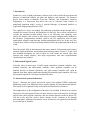
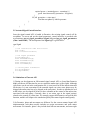
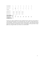
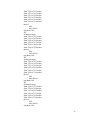
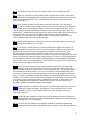
2.1 Intersection Layout with Detectors
Figure 1 illustrates the typical intersection layout with standard NEMA eight-phase
numbering system. The illustration shows similar phasing for both intersecting arteries.
This layout is self-explained clearly and could be modeled easily in Paramics.
The emphasis here is the configuration of detectors. We modeled 16 detectors in a typical
intersection. For each approach, there are three detectors close to the stop line for through
and left turn vehicle presence detection, and one advance detector located at about 150300 feet to the stop line, used to detect vehicles for the extension of the through
movement phase. Although each detector covers all lanes for one approach, each lane has
its own detector in Paramics.
1
8
Approach 2
7
6
5
Approach 1
4
1
7
2
3
4
6
1
5
2
NEMA Phase
12
11 10
3
9
8
Detector num ber
Approach 3
13
14
Detector
15
Approach 4
16
Figure 1. Typical Intersection Layout with NEMA phases
2.2 Configuration of Detectors for Actuated Signal
Generally, there are three groups of detectors in each approach for the typical intersection
in the real world. They are: (1) double loop detectors, located in the through lanes and
very close to the stop bar, for the presence detection of through vehicles; and (2) advance
loop detector, located at almost 150—300 feet from the stop bar, used to detect vehicles
for the extension of the through movement phase; and (3) one long loop detector in the
left turn lane, with the length of about 50-70 feet, for the presence detection of left turn
vehicles. For some intersections, there maybe no advance detector for all approaches or
the minor approaches.
2
To better simulate the functionality of detectors, ideally, detectors should be modeled in
Paramics according to the real-world configuration. However, some problems exist as
follow: (1) Paramics can’t simulate the long-loop vehicle presence detector. The reason is
that Paramics uses the rising and falling edge of loop detector to decide if there is a
vehicle entering the area of the loop, i.e., when the front end of one vehicle passes the
rising edge, vehicle is present on the loop; and when the back end of the vehicle passes
the falling edge, the loop is empty without any vehicle. However, if the loop is long
enough to accommodate more than one vehicle, and there are two or more vehicles on the
loop at the same time, when the first vehicle leaves the loop, the loop becomes empty
according to Paramics even though other vehicles may still stay on the loop. This is
certainly not the case in the real world. (2) Since traffic simulation is a discrete process,
Paramics calculates the location of vehicles at every time step. The loop count variable
does not work properly when the vehicle speed is a little bit high, say 40mph. Visually,
we can see that vehicles passed the loop detector, but the loop count remains the same.
This is a systematic problem of Paramics loop module. (3) Each detector covers all lanes.
We can’t put one long loop detector on the left turn lane, and short detectors on through
lanes.
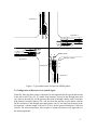
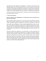
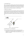
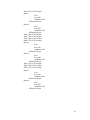
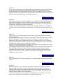
Since the long loop can’t be simulated by Paramics, we have to use some small ones to
replace it. Detectors’ locations for the left turn lane is designed in Figure 2. Three 2m or
6.6 ft long loops are used to mimic one 50ft long loop detector.
31.2 ft
or 9.5 m
12.9 ft
or 4 m
Stop line
49.5 ft
or 15 m
Figure 2. Detectors’ location for the left turn lane
The detector used for left turn can also be used for through movement since the detector
in Paramics covers all lanes. Here we use these two detectors close to stop line to detect
the vehicle presence. An advance detector will be put in the upstream location depending
on the realistic design.
2.3 Data Requirements for Actuated Signal API
Two files need to be prepared for the use of signal control API. One is the “priorities”
file, provided by Paramics, to be used to identify the hierarchy of movements for all
phases. The “priorities” file could be modified and generated through the graphical
display of priority panel in the Edit Junction window. One can also type the proper text
3
into the “priorities” file manually. The other is the so-called “signal_control” file, which
contains all the information in the signal timing chart and intersection layout data.
2.3.1 The “signal_control” file
The “signal_control” file includes all the related information in the signal time chart and
intersection layout data. Figure 1 may need to be referenced when the “signal_control”
file is made. This file should be put to the same directory as that of the road network files.
The format of “signal_control” file is:
total number of actuated signals is: XX
Node
movements
ini_green
extension
max_green
Recall
Lanes
rightturn
detector1
detector2
detector3
detector4
Node_ID
Node_Name
Where “node” is the node ID in the road network, following by the description of the
intersection;
“movements” describes the designated phase diagram, NEMA phase numbering system
is used here;
“ini_green” is the initial green time for 8 phases, corresponding to “Initial” in the Signal
Timing Chart,
“extension” is the extension time for 8 phases, corresponding to “Extension” in the
Signal Timing Chart;
“max_green” is the maximal green time for 8 phases, corresponding to “Max Green” in
the Signal Timing Chart;
“recall” is the recall phases, corresponding to “Min Recall” in the Signal Timing Chart;
“lanes” is the number of lanes corresponding to each movement. If a turning movement
shares a lane with a through movement, consider this to be 0.5 of a lane for this turning
movement. The same lane should be counted as 1.0 lane for the through movement. If
right turn and left turn share a lane, the left one is the one counted as 1.0 (for off-ramp
case);
“rightturn” is the number of right turn lanes from Approach 1 to Approach 4;
“detector1’ to “detector4” are names of detectors. The first four columns of the row of
“detector1’ should contain the detectors for approach 1. You’ll find approach 2-4
counter-clockwise around the junction.
An example of signal_control file is as following:
4
total number of actuated signals is:
node 6 ALTON & ICD
movements
1
2
3
4
ini_green
5
5
5
5
extension
3
5
3
5
max_green
24
32
24
32
recall
2
6
lanes
2
3
2
3
rightturn
1
1
1
1
detector1
aisw
ai2w ai3w
detector2
aiss
ai2s ai3s
detector3
aise
ai2e ai3e
detector4
aisn
ai2n ai3n
1
5
5
3
24
6
5
5
32
7
5
3
24
8
5
5
32
2
3
2
3
aiuw
aius
aiue
aiun
More detailed information about making the “signal_control” file can be found in
APPENDIX 1.
2.3.2 The “priorities” file
The “priorities” file, provided by Paramics, to be used to identify the hierarchy of
movements for all phases. A hierarchy of priorities exists in the order of MAJOR,
MEDIUM, MINOR, and BARRED. MAJOR priority movements are free flow and not
restricted by other streams of traffic. A MEDIUM priority yields to MAJOR streams of
traffic but has priority over MINOR traffic movements. MINOR priority yields to both
MAJOR and MEDIUM traffic flow while BARRED indicates the turn is banned to all
vehicle movements.
The following is an example, which defines the phase 1 priority of intersection “528z”.
Those words after “//” are explanations.
actions 528z
phase offset 0.00 sec
phase 1
0.00
max 100.00
red phase 0.00
fill
all barred except
from 7510 to 7511 minor
from 7511 to 7612 minor
from 7511 to 7510 major
from 7612 to 7614 minor
from 7614 to 7612 major
from 7614 to 7510 minor
// node name
// default stored green time
// maximal green time
// red phase time
// no yellow time
// the following defines priority of movements
More detailed information about making the “priorities” file can be found in APPENDIX
2.
5
2.4 Control Logic and Pseudo Code
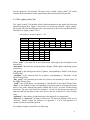
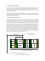
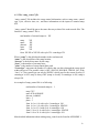
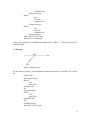
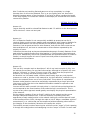
The dual-ring, concurrent concept is illustrated briefly in Figure 3. Note that eight phases
are shown, each of which accommodates one of the through or left turning movements. A
“barrier” separates the north-south phases from the east-west phases. Any phase in the
top group (Ring 1) may be displayed with any phase in the bottom group (Ring 2) on the
same side of the barriers without introducing any traffic conflicts. For simplicity, the
right turns are omitted and assumed to proceed with the through movements.
In full-actuated signal control, all phases at an intersection are actuated, then the length of
each phase, and consequently the cycle length, will vary with each cycle. Some phases
may be skipped if there is no vehicle actuation. To simulate the real controller better, the
order and sequence of phases can also be altered.
Ring 1
W BL
EBL
Left side of barrier
(E-W M ovem ents)
NBL
EBT
W BT
Ring 2
Barrier
SBL
SBT
NBT
Right Side of barrier
(N-S Movements)
Figure 3. Dual-ring concurrent phasing scheme with assigned movements
In order to implement the above dual-ring concept, the pseudo code for the main control
logic is given in the following:
1. Actuated Signal API set up using api_setup( ), includes signal data input, memory
allocation, and initial signal phase set up.
2. At every time step, net_action is called:
For controller intersection = 1 : n {
a. Inquiry the current signal information using signal_inquiry( ).
b. If ( left green time == 0 ) {
Amber and red time are counted.
If ( amber and red time are reached )
Set the next signal phase parameters through signal_action( ).
}
else {
vehicle presence detection (pp_presence_dection ( ) ).
excute the current signal plan (pp_excute_plan ( ) ) {
If ( left green time < extension &&
vehicle presence for extension &&
6
expired green < ( maximal green – extension ) ) {
green time increased by (extension – left green).
}
If ( left green time <= time step )
Find the next phase by vehicle presence
}
}
}
2.5 Actuated Signal Control Interface
Once the signal control API is loaded in Paramics, the existing signal control will be
overridden. To access and set the signal parameters, control interface is provided with
two functions: pp_set_signal_parameters (Signal *sig) and pp_get_signal_parameters
(Char *nodeName ). The description of the Signal type is given below:
type Signal
{
// the intersection name and location
char *node;
char *controllerLocation;
// the signal paramters
int movements[8];
float maximumGreen[8];
float minimumGreen[8];
float extension[8];
float storedRed[8];
// current phase information
int currentPhase;
int expiredTime;
}
2.6 Limitations of Current API
1) During our development on full-actuated signal control API, we found that Paramics
didn't provide an API function for user to control the amber time (yellow light). Although
yellow time can be set in the configuration file, it is universal for all the intersections and
all the time. It is not convenient in the actuated signal case since some phases may be
skipped (the amber time has to be skipped at the same time). In order to simulate the real
world better, our developed APIs have to have a handle on the control of the amber time
associated with each phase. Currently, there is no action_type in the signal_action()
related to the control of yellow time. We strongly suggest that Paramics can provide this
function, and this will improve the simulation quality on actuated signal control greatly.
2) In Paramics, phase and movement are different. For the current actuated signal API
implementation, each phase usually includes two major movements, and some minor
movements. For instance, phase 1 may include dual left turn movements, and some right
7
turn minor movements. Paramics run through phase 1 to phase 8, some phases may be
skipped depends on the vehicle presence. However, each movement has its own initial
green and extension in the signal-timing sheet. Only one set of parameters could be used
in each phase. Although the reasonable set of parameters is calculate and used during the
simulation, and the simulation performance won’t be hurt by doing this, the actual signal
controller can’t be fully simulated in this API. Ideally, we want each phase includes only
one major movement, and two phases can be executed at the same time. But Paramics
can’t do this at the current time.
2.7 Future Development
Real-time Signal Control Optimization for Isolated Intersection Using Wide-Area
Detection Technologies
Effective signal control has long been as one of the most direct methods for relieving
urban traffic congestion. The primary goal of this research is to design a real-time signal
control optimization algorithm to minimize the total delay experienced by traffic and
improve the system performance and safety at insolated signalized intersections via widearea vehicle detection technology. Compared with traditional inductive loop detector,
wide-area detector is capable of detecting vehicles over the entire length of the so called
“dilemma zone” on each approach to the intersection. Machine vision, as one of the most
promising viable wide-area detector, is rapidly approaching to the mature stage to be used
in the field.
Using the provided state parameters of an intersection by wide-area detectors, the
objective function of the optimization algorithm is to minimize the cumulative delay of
all vehicles passing through an intersection, with the weighted time delay for different
vehicle type, subject only to the efficiency, safety and fairness of the traffic in different
approaches. The solution to the objective function is provided through genetic algorithm,
and the rolling horizon concept will be used in the calculation of the optimal signal plan.
The generated signal plan will include optimal phase sequencing and phase parameter
settings. Any arbitrary phase sequencing and phase split with variable length clearance
interval are permitted in the optimal signal plan.
8
3. Actuated Signal Coordination
Coordination is a mode of signal operation designed to allow platoons of traffic to form
and "progress" through several signals with minimum stops and delay. Where signals are
closely spaced and traffic volumes are high, coordination of signals is necessary to avoid
excessive delay and stops.
The actuated signal coordination API inherits most parts of full-actuated signal API, with
additional force-off logic to maintain the background cycle length, and form green band
for a particular phase (sync phase).
3.1 Control Logic and Pseudo Codes
To provide synchronization and maintain the background cycle length, all coordinated
intersection have the same system clock reference point, which is usually the start point
of signal coordination plan. For the fixed-time signal coordination plan, there is an offset,
which is the difference between two green initiations of the sync phase for two adjacent
intersections. However, for the traffic-actuated signal coordination, the sync phase of
every coordinated intersection has fixed series of yield points, and the difference between
yield points is the background cycle length. These yield points are also local clock
reference points to other non-sync phases. The sync phase has minimal bandwidth, i.e.
the sync phase has to start at the time of minimal bandwidth earlier than yield point. To
do so, all other phases have to be cut at certain points, which are so-called force-off
points. These force-off points are usually referenced to the local clock reference point.
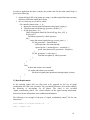
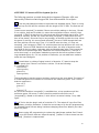
Figure 4 is the phase diagram of coordinated intersection.
Local Clock Reference
Point = 0 sec
Yield Point
Initial Green
Sync Phase
Background Cycle Length
System Clock Reference Point = 0 sec
Figure 4. Actuated Signal Coordination
9
In order to implement the above concept, the pseudo code for the main control logic is
given in the following:
1. Actuated Signal API set up using api_setup( ), includes signal data input, memory
allocation, and initial signal phase set up.
2. At every time step, net_action is called:
For controller intersection = 1 : n {
a. Inquiry the current signal information using signal_inquiry( ).
b. Vehicle presence detection (pp_presence_dection ( ) ).
c. If (left green time > 0) {
Check if this phase should be forced off (pp_force_off ( )).
If (force-off )
Find the next phase by vehicle presence.
else {
excute the current signal plan (pp_excute_plan ( ) ) {
If ( left green time < extension &&
vehicle presence for extension &&
expired green < ( maximal green – extension ) ) {
green time increased by (extension – left green).
}
If ( left green time <= time step ) {
Find the next phase by vehicle presence.
}
}
}
}
else {
Amber and red time are counted.
If ( amber and red time are reached )
Set the next signal phase parameters through signal_action( ).
}
}
3.2 Data Requirements
As the actuated signal API, two files need to be prepared for the use of signal
coordination API. One is the “priorities” file, provided by Paramics, to be used to identify
the hierarchy of movements for all phases. The other is the so-called
“signal_coordination_control” file, which contains all the signal timing information,
intersection layout information, and coordination information.
The following is an example of the part of “signal_coordination_control” file for one
intersection.
total number of actuated signals is:
node 6
4
ALTON & ICD
10
movements
1
2
3
4
ini_green
5
5
5
5
extension
3
5
3
5
max_green
24
60
24
32
recall
2
6
lanes
2
3
2
3
rightturn
1
1
1
1
detector1
aisw
ai2w ai3w
detector2
aiss
ai2s ai3s
detector3
aise
ai2e ai3e
detector4
aisn
ai2n ai3n
sync_phase
2
6
cycle_length 60
force_off
36
60
18
27
yield_point
5
system_clock 0
5
5
3
24
6
5
5
32
7
5
3
24
8
5
5
32
2
3
2
3
36
60
18
27
aiuw
aius
aiue
aiun
The data for signal coordination has been attached after the intersection layout data for
each intersection. Besides to the yield point of the sync phase, all other phases have
force-off points, referenced to the local clock reference point. Notice that the maximal
green time of primary sync phase has to be the cycle length, since the green time of sync
phase may occupy the entire cycle if there is no conflict traffic.
11
4. Actuated Ramp Control
There have been a number of strategies to release vehicles into the mainline freeway
traffic, each with different demands on sophistication of control and detectorization. The
actuated ramp API here is an implementation of time-based ramp control algorithm in
Paramics. This API will not calculate the ramp rate/cycle but require them as data inputs.
Other more complex actuated ramp APIs could be developed based on this one by
integrating ramp rate/cycle calculation with respect to real traffic data inputs.
4.1 Ramp Layout with Detector
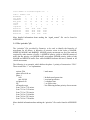
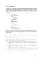
A typical ramp layout with detector is given in Figure 5. Vehicles are released from ramp
to the mainline traffic at a fixed ramp metering rate during the certain time period. Every
vehicle has to stop before the stop lane, waiting for the green signal. The detector for
sensing the presence of a vehicle allows the signal to rest in red, avoiding potential
confusion to a driver approaching the signal, due to the short greens. The ramp-control
signal, mounted close to driver level, generally provides two indications, green and red
only.
Mainline Traffic
S
to
p
La
ne
de
c
te
to
r
Figure 5. A typical ramp metering layout
4.2 Data Requirements for Actuated Ramp API
In order to run Paramics with the actuated ramp API, two files need to be prepared:
(1) “ramp_control” file is the input of actuated ramp API including the ramp control
information, such as ramp name, control type, cycle, effective time, etc.
(2) “priorities” file is a system file of Paramics, provided with the action and phase
definition of a ramp signal.
12
4.2.1 The “ramp_control” file
“ramp_control” file includes the ramp control information, such as ramp name, control
type, cycle, effective time, etc., and these information are the inputs of actuated ramp
API.
“ramp_control” should be put to the same directory as that of the road network files. The
format of “ramp_control” file is:
total number of actuated ramps is: XX
ramp
XX
name
XX
detector XX
lanes
XX
plans
XX
from XX:XX to XX:XX with cycle XX controltype XX
Where “ramp” is the global node number in the road network,
“name” is the description of the ramp location,
“detector” is the detector name for the ramp,
“lanes” is the number of on-ramp lanes,
”plans” is the number of ramp control plans, and
“controltype” represents the number of vehicles that can drive through the ramp signal
within one green. The possible value is OFF, SINGLE, DOUBLE, TRIPLE, ON. If the
“lanes” is 2, the control type can only be SINGLE vehicle pass for the reason of safety. If
controltype is OFF, ramp is always OFF (ramp is closed); if controltype is ON, ramp is
always ON.
An example of ramp_control file is as following:
total number of actuated ramps is: 1
ramp 7567
name ICD & NB405E
detector icdnb405
lanes 2
plans 5
from 0: 0 to 6: 0 with cycle 0 controltype ON
from 6: 0 to 9: 0 with cycle 6 controltype SINGLE
from 9: 0 to 15: 0 with cycle 0 controltype ON
from 15: 0 to 19: 0 with cycle 6 controltype SINGLE
from 19: 0 to 24: 0 with cycle 0 controltype ON
More detailed information about making ramp_control can be found in APPENDIX 1.
13
4.2.2. The “priorities” file
“priorities” file, a system file of Paramics, provided with the action and phase definition
of a ramp signal. There are only two phases for each ramp signal. Phase 1 is the red
signal to stop vehicles from entering the freeway directly. Phase 2 is the green signal to
release the waiting vehicle into the freeway. An example of the “priorities” is as
following:
actions 3480
phase offset 0.00 sec
phase 1
0.00
max 36.00
red phase 0.00
fill
all barred except
phase 2
0.00
max 36.00
red phase 0.00
fill
all barred except
from 3907 to 3452 major
Where “fill” means no yellow will be shown. The initial lengths for both phases are set to
0 according to the above example, and these lengths will be reset when the actuated ramp
API is running.
More materials regarding the “priorities” file could be found Paramics user manual. You
can also find some useful hints from the Appendix 2.
4.2.3 Constant Parameters
Some constant parameters are included in “actutated_ramp_c.h” file may influence the
performance of simulation. These parameters includes:
(1) SINGLE_VEH: The green time for one vehicle to pass the ramp signal per cycle
(2) DOUBLE_VEH: The green time for two vehicles to pass the ramp signal per
cycle
(3) TRIPLE_VEH: The green time for three vehicles to pass the ramp signal per
cycle
(4) DEFAULT_RED_AMBER: Red/amber signal time
(5) MAX_PLAN: The maximal number of the time-of-day ramp control plans
(6) RAMP_CYCLE: If no vehicle arrives within a RAMP_CYCLE, a green time will
be given eventually in case that a vehicle before the stop line may not be detected
by the detector because of the system problem of Paramics.
14
The default configuration of those control parameters is as following:
#define SINGLE_VEH 2.5
#define DOUBLE_VEH 4.5
#define TRIPLE_VEH 6
#define MAX_PLAN 10
#define DEFAULT_RED_AMBER 0
#define RAMP_CYCLE 20
4.3 Control Logic and Pseudo Code
In the API control logic, the time-based ramp metering rate is fixed within the specific
time window, but can be changed according to the different time period. The metering
rate is determined by the expected mainline volume and by a decision on how much
volume can be allowed in from the particular ramp. The green indication is generally 2 to
3 seconds, sufficient to pass one vehicle.
As an illustration, suppose the ramp signal cycle length is 10 seconds from 4pm to 6pm.
This is one vehicle every 10 seconds, so that a setting of a 2 sec of green followed by 8
sec of red could be used. The metering rate in this case is 360 vph.
The implemented actuated ramp API in Paramics has several limitations. (1) Although
the carpool lane has no ramp signal, Paramics can’t simulate the condition that one lane
has signal, the other has not. (2) For unclear reasons, sometimes the presence detector of
Paramics does not work correctly, i.e. sometimes a vehicle can’t be detected though it is
present on the detector. This case is very rare, however, this may cause severe problems
in the simulation since all the following vehicles are blocked, and the signal may remain
red all the time. To solve this problem, a green signal is given as long as the time of red
signal is over RAMP_CYCLE, which is described in the above chapter.
The control logic is given in the following pseudo codes:
(1) Initialization using api_setup()
Read in all ramp information.
Allocate memories for all pointers to be used.
Store all necessary ramp information to global data structures.
Check the existence of ramp nodes and correspondent detectors.
Initialize the ramp signals based on the initial simulation time.
(2) Main program using net_action()
Get simulation time.
For controlled ramp = 1 : n {
Check the current running phase.
Get green left time of the current running phase
Find the correct ramp control plan according to the simulation time
If (ramp cycle length changed due to entering another time period) {
15
notify the operator
Recalculate the green times for the 2 phases
}
If (controltype is always ON)
set next green time for “always ON”
Else if (controltype is always OFF)
set next green time for “always OFF”
Else{
If ( the running phase is 2 && green left time <= time step )
Set the next green time for phase 1
Else if (the running phase is 1){
If (no vehicle presence) {
If(the running time is less than RAMP_CYCLE)
continue to increment green time for phase 1
Else (the running time is equal to RAMP_CYCLE)
set the next green time for phase 2
}
else
Set the next green time for phase 2
}
}
}
4.4 Ramp Control Interface
There are two interface functions to get and set ramp metering rate for a specific ramp.
The prototypes are as follows:
void pp_set_ramp_parameters( RAMP *ramp, Bool parameter )
RAMP *pp_get_ramp_parameters( char *rampnode )
Where parameter = TRUE means to set a new ramp cycle that overrides the default one
while parameter = FALSE means to restore default ramp cycle according to ramp_control
file. The rampnode is the name of ramp as shown in ramp_control file. RAMP is a
structure of ramp data, whose definition is:
typedef struct Ramp_data RAMP;
struct Ramp_data{
char *node;
char *name;
int type;
int cycle;
};
16
4.5 Future Development
The ramp metering algorithms developed to date can be classified into one of four
general categories: (1) fixed-time or time-of-day, (2) traffic-responsive, (3) hybrids
combining attributes of traffic-responsive and time-of-day algorithms, and (4) integrated
freeway/surface-street metering algorithm.
The integrated freeway/surface-street metering algorithm, addressing real-time control of
ramp meters of a freeway segment, with consideration of the traffic volumes entering and
leaving the freeway from/to arterials, and the regulation of these volumes via real-time
setting of ramp metering rates, is the research direction of ramp metering algorithms.
This kind of ramp metering control algorithm should contain the following modules: (1)
traffic anomaly detection; (2) area-wide coordination; (3) ramp rate regulation. These
modules need to be developed separately with the output of ramp rates/cycles for all
ramps by using more control parameters, including queue length, upstream traffic
condition and downstream traffic condition, etc.
The current ramp API could be extended by the development and test of other advanced
ramp control algorithms. These algorithms can be implemented through the call of the
interface functions provided by this actuated ramp API.
17
Reference:
1. McShane, W. R., Roess, R. P., and Prassas, E. S., “Traffic Engineering”,
Second Edition, Prentice Hall, 1998.
2. NCHRP Web Document, “Capacity Analysis of Traffic-Actuated
Intersections: Final Report”, 1998.
http://www.nap.edu/openbook/nch010/html/79.html.
3. “Model 170 Traffic Signal Control Operational Manual”, Caltrans, 1985.
4. “Multisonics Model 820A-VMS Vehicle Management System User Guide”,
Intersection Development Corporation, 1994.
5. “Modeller V3.0 User Guide”, Quadstone Ltd., February 2000.
6. “Modeller V3.0 Reference Manual”, Quadstone Ltd., February 2000.
7. “Processor V3.0 Reference Manual”, Quadstone Ltd., February 2000.
8. “Analyzer V3.0 User Guide”, Quadstone Ltd., February 2000.
9. “Analyzer V3.0 Reference Manual”, Quadstone Ltd., February 2000.
10. “Programmer V3.0 User Guide”, Quadstone Ltd., February 2000.
11. “Programmer V3.0 Reference Manual”, Quadstone Ltd., February 2000.
18
APPENDIX 1 Working Steps For Collecting Junction / Ramp Information
Part 1 Junction And Offramp
Documents required:
(1)
(2)
(3)
(4)
Worksheet for intersection
Signal Timing Chart obtained from the proper government agency (i.e. Caltrans)
Layout of the intersection
“detector” file of Paramics
Working steps:
Please see the attached format of “signal_control” file.
(1) Write down the name of the intersection, i.e. Alton & Barranca, and the signal ID that is
shown in the first page of signal timing chart.
(2) Find the first NEMA movement, generally a left turn, in the Signal Timing Chart. Write
down the turn arrow and the movement number 1 (all NEMA movements / phases will be
decided based on the 1st one). If the first movement is none, please do a regular analysis
based on the movement sequence on the first page of the Signal Timing Chart and define
what the 1st movement should be if it exists. Then we regard that movement as the 1st
movement though it doesn’t exist. Then write down the turn arrow and the movement
number 2 for NEMA movement 2 at the opposite approach.. The approach that the 1st
NEMA movement locates is defined as approach 1 here. The counter-clockwise
approaches around the junction are defined as approach 2, 3, 4.
(3) Write down the two street names, the detector IDs, the junction node name and the four
neighbouring nodes on four approaches.
(4) Fill out the 3-5 rows (ini_green, extension, max_green) of the table in the worksheet. The
ini_green corresponds to the “Initial”(green time) and the max_green corresponds to the
“Max Green” in the Signal Timing Chart.
(5) Find out the recall movement from the Signal Timing Chart. Enter the two recall
movement numbers to the first two columns of “recall” row. If there is no recall
movement, just write “0”. If only one recall, the second column of recall is “0”.
(6) Compare the 8 movements, defined for the intersection just now, with the standard
NEMA phases / movements. In general, the values written in the “movement” row should
be 1,2, …,8. But the second half phases should require more attention. It’s possible to
have a sequence change (3,4<->7,8). Write down the corresponding movement number
according to the standard NEMA movements. Of course the first movement must be 1
since that’s the basis.
(7) From layout, find out how many lanes for one movement. Fill them in the “lanes” row. If
a turning movement shares a lane with a through movement, consider this to be 0.5 of a
lane for this turning movement. The same lane should be counted as 1.0 lane for the
through movement. If right turn and left turn share a lane, the left one is the one counted
as 1.0 (offramp).
(8) From layout, find out how many right turn lanes for an approach. Write down these
numbers in the rightturn row. The 1st approach corresponds to the approach direction as
NEMA movement 1 found in step 2. The other approaches can be defined counterclockwise.
(9) The “detector1’ to “detector4” rows will fill in the name of detectors that can be found
from “detector” file of Paramics. The first four columns of the row of “detector1’ should
19
contain the detectors for approach 1. You’ll find approach 2-4 counter-clockwise around
the junction. The detectors on the approach2-4 should fill in rows of “detector2” to
“detector4”. See figure 2 for the detailed position of the detectors.
(10)
For the missing movements, some intersection will not have all movements, such
as T-junctions. Write down “9” at each row except the “recall”, which includes two kinds
of information, and “movement”, which represents if it’s the same as the NEMA
standard. The right turn lanes information should be analyzed. For locations where there
are no detectors, enter “N/A” into these spaces.
Notes:
(1) In order to distinguish the Paramics phase and the NEMA phase, we just use movement
instead of phase in NEMA
(2) Since only one yellow time can be used for the whole one simulation, the default yellow
time is defined as 3 seconds. The red clearance is set to 1 seconds.
(3) The standard NEMA phases / movement is shown in Figure 1.
(4) The numbering system for the detectors is shown in Figure 2. Normally, detectors 4,8,12
and 16 are the advanced detectors.
(5) Please write down OFFRAMP if the junction is an off_ramp.
4
7
6
5
1
2
3
8
Figure 1 NEMA standard movement / phase
56 7
8
Approach 2
12 3
4
Approach 1
Approach 3
12 11 10 9
13 14 15 16
Approach 4
Figure 2 Detector numbering based on NEMA phases
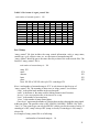
20
TABLE 1 The format of “signal_control” file:
total number of actuated signals is: XX
node
movements
ini_green
extension
max_green
recall
lanes
rightturn
detector1
detector2
detector3
detector4
Part 2 Ramp
“ramp_control” file that includes the ramp control information, such as ramp name,
control type, cycle, effective time, etc., are the inputs of actuated ramp API.
“ramp_control” should be put to the same directory as that of the road network files. The
format of “ramp_control” file is:
total number of actuated ramps is: XX
ramp XX
name
detector
lanes
plans
from XX:XX to XX:XX with cycle XX controltype XX
XX
XX
XX
XX
Where “total number of actuated ramps is: XX” is only shown in the first row of
“ramp_control” file. The meaning of other rows in “ramp_control” is as follows:
“ramp” is the global node number in the road network
“name” is the name of the ramp used for linking Paramics and Cartesius
“detector” is the correspondent name of the detector for a ramp
“lanes” is the number of on-ramp lanes
”plans” is the number of ramp control plans
“controltype” represents the number of vehicles that can drive through the ramp signal
within one green. The possible value is OFF, SINGLE, DOUBLE, TRIPLE, ON. If the
“lanes” is 2, the control type can only be SINGLE vehicle pass for the reason of safety. If
controltype is OFF, ramp is always OFF (ramp is closed); if controltype is ON, ramp is
always ON.
An example of ramp_control file is as following:
total number of actuated ramps is: 10
21
ramp 7567
name ICD & NB405E
detector icdnb405
lanes 2
plans 5
from 0: 0 to 6: 0 with cycle 0 controltype ON
from 6: 0 to 9: 0 with cycle 6 controltype SINGLE
from 9: 0 to 15: 0 with cycle 0 controltype ON
from 15: 0 to 19: 0 with cycle 6 controltype SINGLE
from 19: 0 to 24: 0 with cycle 0 controltype ON
22
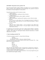
APPENDIX 2 Preparation of the “priorities” file
Since the maximum number of phases Paramics can support is 15, we can use 8 Paramics
phases to simulate various combinations of an actuated signal. The “priorities” file has all
the definition of actions and phases for each junction.
Generally, there are four cases for a junction or ramp:
1. + shape junction #1
NEMA standard phases, right-turn is allowed as minor.
2. + shape junction #2
Not NEMA standards phases, phases might be combined.
3. T shape junction
NEMA standard phases, right-turn (if the right turn exists) is allowed as minor.
4. Off-ramp
There are only two active phases. One is for through movements of vehicles on
the surface street, and the other one is for the left turn movements of vehicles
from the off-ramp.
5. On-ramp
There are only two phases. Phase 1 is the red signal to stop vehicles from
entering the freeway directly. Phase 2 is the green signal to release the waiting
vehicle into the freeway.
It’s possible for some intersections to have more complex situation and thus we should do
a regular analysis (to get the category) for each intersection in order to make the
“priorities” file. If there are some special features about the intersection, we should
understand it in detail first.
1. Notes for making “priorities” file
1) The first two lines in “priorities” is always like the following:
actions 8
phase offset 0 sec
The string after “actions” is the name of node in Paramics.
2) For any junctions except on-ramp, 8 phases will be written in “priorities” file. Some
phases only have the following lines:
phase 6
0.00
max 100
red phase 0.00
all barred except
This means there is no action of the phase. In general, there is another line in “priorities”:
fill that is often adding to the line between “red phase” and “all barred except”. If there is
a “fill”, that means no amber light being shown.
3) The max green is set to 100 sec for the reason that we can set any length of max green
time when the actuated signal is running.
23
4) If you want to add a new action to a phase, you can do that. The result is that that new
movement is allowed in that phase. Thus if there are only two phases, one for each
direction with the permitted left turn, permitted right turn and through movement, we can
regard it as phase 4 or 8 with some minor movements. At that time the dominant
movement is the through movement.
2. Examples
2.1 + shape junction #1
7510
528z
7511
7614
7612
Figure 1. Intersection Layout
For the intersection as Figure1, the definition of phases and actions in “priorities” file
would be:
actions 528z
phase offset 0.00 sec
phase 1
0.00
max 100.00
red phase 0.00
fill
all barred except
from 7510 to 7511 minor
from 7511 to 7612 minor
from 7511 to 7510 major
from 7612 to 7614 minor
from 7614 to 7612 major
from 7614 to 7510 minor
phase 2
0.00
max 100.00
red phase 0.00
fill
all barred except
24
from 7510 to 7511 minor
from 7511 to 7612 minor
from 7511 to 7614 major
from 7511 to 7510 major
from 7612 to 7614 minor
from 7614 to 7510 minor
phase 3
0.00
max 100.00
red phase 0.00
fill
all barred except
from 7510 to 7511 minor
from 7511 to 7612 minor
from 7612 to 7614 minor
from 7614 to 7511 major
from 7614 to 7612 major
from 7614 to 7510 minor
phase 4
0.00
max 100.00
red phase 0.00
fill
all barred except
from 7510 to 7511 minor
from 7511 to 7612 minor
from 7511 to 7614 major
from 7612 to 7614 minor
from 7614 to 7511 major
from 7614 to 7510 minor
phase 5
0.00
max 100.00
red phase 0.00
fill
all barred except
from 7510 to 7511 minor
from 7510 to 7614 major
from 7511 to 7612 minor
from 7612 to 7511 major
from 7612 to 7614 minor
from 7614 to 7510 minor
phase 6
0.00
max 100.00
red phase 0.00
25
fill
all barred except
from 7510 to 7511 minor
from 7510 to 7612 major
from 7510 to 7614 major
from 7511 to 7612 minor
from 7612 to 7614 minor
from 7614 to 7510 minor
phase 7
0.00
max 100.00
red phase 0.00
fill
all barred except
from 7510 to 7511 minor
from 7511 to 7612 minor
from 7612 to 7511 major
from 7612 to 7614 minor
from 7612 to 7510 major
from 7614 to 7510 minor
phase 8
0.00
max 100.00
red phase 0.00
fill
all barred except
from 7510 to 7511 minor
from 7510 to 7612 major
from 7511 to 7612 minor
from 7612 to 7614 minor
from 7612 to 7510 major
from 7614 to 7510 minor
2.2 + shape junction #2
9
6
11
12
8
Figure 2. Intersection Layout
26
In this example, there are only 2 phases, each one corresponds bi-directions along one
intersected street, where three movements, left, through, right are allowed. For the
intersection as Figure 2, the definition of phases and actions in “priorities” file would be:
actions 6
phase offset 0 sec
phase 1
0.00
max 100
red phase 0.00
all barred except
phase 2
0.00
max 100
red phase 0.00
all barred except
phase 3
0.00
max 100
red phase 0.00
all barred except
phase 4
0.00
max 100
red phase 0.00
all barred except
from 12 to 11 major
from 11 to 12 major
from 12 to 8 medium
from 11 to 9 medium
from 12 to 9 minor
from 9 to 11 minor
from 11 to 8 minor
from 8 to 12 minor
phase 5
0.00
max 100
red phase 0.00
all barred except
phase 6
0.00
max 100
red phase 0.00
all barred except
phase 7
27
0.00
max 100
red phase 0.00
all barred except
phase 8
0.00
max 100
red phase 0.00
all barred except
from 9 to 8 major
from 8 to 9 major
from 9 to 12 medium
from 8 to 11 medium
from 12 to 9 minor
from 9 to 11 minor
from 11 to 8 minor
from 8 to 12 minor
2.3 T-shape junction
7414
7411
7412
7413
Figure 3. Intersection Layout
For the intersection as Figure 3, the definition of phases and actions in “priorities” file
would be:
actions 7411
phase offset 0 sec
phase 1
0.00
max 100
red phase 0.00
all barred except
phase 2
0.00
max 100
red phase 0.00
all barred except
from 7412 to 7414 major
from 7412 to 7413 major
from 7414 to 7413 minor
28
from 7413 to 7412 minor
phase 3
0.00
max 100
red phase 0.00
all barred except
phase 4
0.00
max 100
red phase 0.00
all barred except
from 7414 to 7412 major
from 7412 to 7414 major
from 7414 to 7413 minor
from 7413 to 7412 minor
phase 5
0.00
max 100
red phase 0.00
all barred except
phase 6
0.00
max 100
red phase 0.00
all barred except
from 7413 to 7414 major
from 7414 to 7413 minor
from 7413 to 7412 major
phase 7
0.00
max 100
red phase 0.00
all barred except
phase 8
0.00
max 100
red phase 0.00
all barred except
29
2.4 Off-ramp
566z
2555y
5448
1816z
Figure 4. Intersection Layout
For the intersection as Figure 4, the definition of phases and actions in “priorities” file
would be:
actions 566z
phase offset 0 sec
phase 1
0.00
max 100
red phase 0.00
all barred except
phase 2
0.00
max 100
red phase 0.00
all barred except
phase 3
0.00
max 100
red phase 0.00
all barred except
phase 4
0.00
max 100
red phase 0.00
all barred except
from 2555y to 5448 major
from 5448 to 2555y major
phase 5
0.00
max 100
red phase 0.00
all barred except
phase 6
0.00
max 100
30
red phase 0.00
all barred except
phase 7
0.00
max 100
red phase 0.00
all barred except
phase 8
0.00
max 100
red phase 0.00
all barred except
from 1816z to 2555y major
from 1816z to 5448 major
Notice that right turn is prohibited according to the “phase 4”. That will protect the
mainline traffic.
2.5 On-ramp
3480
3452
3907
Figure 5. Ramp Layout
For the ramp as Figure 5, the definition of phases and actions in “priorities” file would
be:
actions 3480
phase offset 0.00 sec
phase 1
9.50
max 36.00
red phase 0.00
fill
all barred except
phase 2
2.50
max 36.00
red phase 0.00
fill
all barred except
from 3907 to 3452 major
31
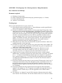
APPENDIX 3: Paramics API Development Qs & As
The following questions we asked during the development of Paramics APIs were
answered by Paramics technical support Mr. Scott Aitken and Mr. Ewan Speirs.
Q1. I use the plan/phase/priorities to implement the actuated signal. There is a long
stopline loop for the left turn vehicles with the length of 50-75 feet. The facts are as
follows:
I want to use occupied[ ] to decide if there are vehicles waiting on the loop, I found:
if one vehicle, that can be called #1, enters the loop(before that no vehicle), then
occupied[ ]=TRUE. At that time it's red signal and thus the vehicle has to stop. Then
another 2 vehicles, #2 and #3, enters the loop (occupied[ ]=TRUE within the red
time of the phase). Since the loop is long enough, all three are within the loop. When
the green is coming, #1 runs out and occupied[ ] turns to FALSE though there are
still two vehicles over the loop. Then, if no vehicle enter the loop, #2 runs out,
occupied[ ] can't change to TRUE. if a vehicle enters the loop and then #2 runs out,
occupied[ ] turns to TRUE. Based on the above facts, the loop in Paramics works
according to the two edges, upstream edge and downstream edge. That means the
loop can not be present type loop. Please tell me some solutions to it, use two or
more short loops, or some basic methods to cope with the left turn phase of dual
ring actuated signal. Or, if it is a problem of Paramics, you can add some codes to
make the loop intelligent.
Q2. I found there is a delay of signal control in Paramics. If I want to stop the
current green time if there is no left turn vehicle. I'll do the following:
if (!occupied[1]){
report time;
report green1;
green1=0;
report green1;
}
I have thought to stop the green1 and then continue to the next phase. The result of
it is that the green1 will continue to increase to the maximum green. Then I found
that the reports are:
time =6.5
green1=7
.....
green1=7.5
So, since the condition !occupied[1] is satisfied then, a loop produces until the
maximum green. Of course, I have solved the problem to avoid to use if
(!occupied[1]). Based on the above, I think there is a second >delay. Is my idea
right?
Q3. UC Irvine has the plugin code of controller 170. The output of it are four files:
plan, phase, priorities, detectors. Is that the correct way to do the API programming
for actuated signal? We are doing it without changing those files. What's your idea
about our plan?
Q4. We are using API programming to replace the plan/phase method. But I found
there is no API function that can output occupied[ ] values. I'd like to know how the
occupied[ ] function is implemented.
32
Q5. I would like to know if I can run Paramics under Linux, a personal Unix?
Q6. I reset my computer's clock(forward to Oct.19) because of other needs. After
that, I found that the Windows version Paramics entered the demonstration with the
error: Clock Reset Detected. Then I realized that the license of Paramics will be
expired on Sep. 30.
Q7. I have another question about what you told me last time. The following is
based on three 6.6 feet loops instead of one 50 feet loop.You told me that Paramics
uses occupancy to get occupied(). Before, we use count to get occupied(). Thus I
tried to change and use incomplete occupancy, but it doesn't work well. After my
observation, I found that the loop nearest the junction works OK, but the second and
third loops(even the loop in the middle of the link) can't reflect incomplete
occupancy. They just kept the occupancy value of last passing vehicle when no
vehicle appears after last one on that approach.
Q8. Because of the problem of occupancy(), we use incomplete gap() to do the job
of detecting the presence. Is it all right?
Q9. One problem I should point out is that Paramics can't detect the presence of
vehicles sometimes when the vehicle is over the detector. Because we have three
detectors to simulate the long loop (and several lanes for a movement), this
shortcoming is not serious for us. But for ramp, there is only one loop. If the
detector failed to detect the presence of a vehicle, no green will be given to the ramp
signal (of course we have solved the problem using our tricks). I have thought this is
an unavoidable problem of simulation software because it works based on sampling
at time step. This is my understanding. I don't know if it's correct. Or if Paramics can
solve the problem totally, that'll be great.
Q10. During our development on full actuated signal control API, we found that
Paramics didn't provide an API function for user to control the amber time (yellow
light). Although yellow time can be set in the configuration file, it is universal for all
the intersections and all the time. It is not convenient in the actuated signal case
since some phases may be skipped (the amber time has to be skipped at the same
time). In order to simulate the real world better, our developed APIs have to have a
handle on the control of the amber time associated with each phase. Currently, there
is no action_type in the signal_action() related to the control of yellow time. We
strongly suggest that Paramics can provide this function, this will improve the
simulation quality on actuated signal control greatly.
Q11. Another question is related to the parallel processing with Paramics. Since our
networks become larger and larger, this feature is very important to us. Is this
feature available in the current version of Paramics? Can you give me some
information on this?
Q12. I think that two neighboring links have some overlapping areas in Paramics. I
get this conclusion from tracing a vehicle and adding two detectors on the both sides
of neighboring links. Is my idea right?
Q13. I'd like to know if Paramics use different models for freeway/highway and
surface streets because Corsim uses different ones in order to simulate the different
33
traffic well. If so, is it possible for a vehicle to change its pointer if it travel from the
surface street to the freeway?
Answer 1:
I understand the problem here; we have been looking at the development of NEMA
170 logic and have a plug-in that emulates the logic. It does need some work
however to finish it off. I would be interested in hearing more about your work at
UCI and your background.
My suggestion is to implement several smaller loop (about 6.6 ft or 2.0 m) and to
use combine the occupied condition, for example:
If ((occupied [1]) or (occupied [2]) or (occupied [3])) { …. }
RETRUN TO THE TOP
Answer 2:
The problem is with the green1 time you had set. The program will run through the
VA code every timestep (which can be every 1/2 second). The green1 time is the
time left to run (the value of 0 will mean the next timestep as it cannot chane as it is
being explored) if the 'if' statement is true in the next timestep also then it will again
attempt to implement the change in the next timestep. Thus it was running to max.
To avoid this happening a switch can be used. Set a parameter = 0 and activate a
switch when the initial conditions are met
if (parameter [1] = 0) { if ((green1 = 7 ) and (occupied [1] = 0)) { ## Changes i.e.
green1 = 0.5 parameter [1] = 1; }
Remember to reset the switch to 0 once the changes to the phasing have been
completed. This could be achieved using code such as this:
else if (occupied [1] = 1) { parameter [1] = 0; }
RETRUN TO THE TOP
Answer 3:
The output is designed to produce and update the normal working Paramics files;
this is so the user can edit them if required. When developing plug-ins we attempt to
make them as transparent as possible so that users can understand them and make
manual edits without having to recompile a plug-in.
We are interested in your development of the NEMA 170 controller and would be
eager to hear your thoughts on the plug-in and it's future development.
RETRUN TO THE TOP
Answer 4:
The VA Signals pseudo code uses the occupied as occupancy of greater than 0.
Therefore this would be the way to replicate the occupied function in the API.
RETRUN TO THE TOP
34
Answer 5:
Prior to porting Paramics to the Windows OS we did produce a Linux version (approx.
2 years ago). Unfortunatly the Linux platform did not prove a good host to the
Paramics software as it was particularly slow and very unstable. The Linux port was
discontinued soon after due to lack of demand from users. If demand from yours was
sufficient high we would consider revisiting this option.
RETRUN TO THE TOP
Answer 6:
The problem that you are facing is detailed in the FAQ section of the Customer Area.
This is the way that the license protection system works, once the date has been
stamped on the HASP key then it will not initialise a licensed copy of Paramics prior
to that date. Therefore you have two options:
i) Wait until the 19/10/00 when the timestamp will allow Paramics to be initialised.
ii) Use one of the other HASP keys possessed by UCI that has not been used on your
PC.
RETRUN TO THE TOP
Answer 7:
Thank you for your email regarding the Occupancy [N] running values returned by
the loop detectors.
Our apologies for the delay in replying to your query, however it did require a great
deal of consideration. Thanks to your help in outlining your problems we have
discovered a bug in the program that was not in previous versions of the software.
The bug occurred due to conflict with other processes designed to ensure backward
portability with earlier version of Paramics modeller.
The bug has now been fixed and occupancy (incomplete) will now display the correct
values in the forthcoming build of the software.
Following QA procedures these changes will be included in the forthcoming Version 3
build 6 release scheduled for 31st October 2000. However should you have an
immediate and pressing need for access to Parmaics modeller with this bug fixed
please let us know as we may be able to generate an intermediate version of the
software for your use only.
RETRUN TO THE TOP
Answer 8:
This is a workaround, however occupancy () incomplete is the correct way to model
presence.
RETRUN TO THE TOP
Answer 9:
Because Paramics is set to emulate real detector data there is always a problem
when looking at real data emulation and gathering 'perfect' data. In reality if a
vehicle has not exited a loop when another vehicle has entered the loop then the
presence will continue to run and the count () will not increase. This is due to the
rising and falling edges of the loop detector.
To prevent this from occurring shorten the length of the loop slightly and this will
make it more difficult for two vehicles to occupy the same loop.
35
Also if vehicles are travelling fast and pass over a loop completely in a single
timestep then it will not be detected. This is, as you rightly point out, due to the
discrete timestep nature of the simulation. If you wish to either increase the length
of the loop slightly or increase the number of timesteps per second then this should
remove this problem.
RETRUN TO THE TOP
Answer 10:
I agree that this would be a beneficial feature to add. I'll add this to the development
list for Version 3.1 due out next year.
RETRUN TO THE TOP
Answer 11:
V3.0 of Paramics Parallel is not commercially available at present as we feel it
requires further work to ensure stability and compatability with Paramics Modeller for
commercial/academic use. As the demand for the parallel processing version of
Paramics is not as great as that for other features, and with the finite resources we
have available to us, we have to concentrate on those feature requested by the
majority of users.
I has been the case that we have accelerated development of certain features of the
past, aided by outside funding form third parties i.e. the European Commission and
UCI-Irvine. Realistically, due to the limited demand and specialist nature of Paramics
Parallel, we would require this sort of input from third parties to accelerate the
development of this feature.
RETRUN TO THE TOP
Answer 12:
This is a fairly complex topic to describe so I will do my best to explain it fully. You
are almost correct when you say that links overlap, although to be specific it's more
that the "influence" or "scope" of one or more links, rather than the physical link
structure, can overlap into and through nodes or junctions.
As Paramics is a link based model, vehicles cannot easily have any real physical
presence on node or junction in the network as, by their definition, nodes are only a
point in the network where one of more links meet. This problem is complicated
because nodes/junctions cannot be realistically represented by a simple point that
joins one or more links due to the detailed information needed to replicate a real
world road geometry.
You can see this when you edit link kerb points i.e. the link kerb points/stoplines do
not correspond to the exact location of the node the link is connected to. This is
correct as any other approach would greatly oversimplify the physical representation
of the network.
So the problem remains of how to "track" vehicles in the network as they move
through nodes and between links. To do this Paramics continually scans the
approaches of each node/junction in the network looking for vehicles that will need
to be transferred from link A, through the node to link B. When a candidate vehicle if
encountered (i.e. a vehicle that can be transferred without effecting other traffic or
the integrity of the simulation) Paramics will transfer the vehicle.
The transfer process involves removing the vehicle from the "scope" of link A passing
it through the node/junction and reassigning it to the "scope" of link B. In some case
36
this transfer process can take place before the vehicle has reached the end of link A
i.e. if the vehicle is very close to the junction and has priority etc. In this way the
transfer process can be pre-emptive for very congested networks. When this
happens the vehicle will be moved to the "scope" of link B but, in the simulation, will
still be treated as if it is physically located on link A and still has to pass through the
junction. The visualisation is not adversely effected, nor is the interaction and
cause/effect the vehicle has on any other the vehicle on the two link A and B.
The 'distance' attribute of the vehicle however will be effected as even though the
vehicle_link() call will return link B the real position of the vehicle is still X meters
from the end of link A. This is why you see the strange changes in vehicle distance in
your plugin (distance > link length), i.e. because the vehicle is in the process of
being transferred between links and across a node.
You could try using the API overload functions below rather then the approach you
use at present as these are better integrated into the transfer process and should
give more tangible results.
- void vehicle_tagged_move(void *Vp, void *linkp, float distance, float speed); - void
vehicle_move(void *Vp, void *linkp, float distance, float speed); - void
vehicle_transfer(void *Vp, void *linkp, void *link2p); - void vehicle_tagged_
transfer(void *Vp, void *linkp, void *link2p)
RETRUN TO THE TOP
Answer 13:
The car-following and lane changing models used in Paramics do differ in some
aspects depending on whether the vehicle is travelling on a highway of urban link.
Vehicle pointer is the memory address that represents the top level of a vehicle
structure. Obviously this is not possible. You can query the link/link type that a
vehicle is currently travelling on so you can determine if the vehicle is travelling on
an urban or highway link; please see the void* vehicle_link(void *Vp) function in
Paramics Programmer. If this is not what you mean please expand on your query.
To trace vehicles through the network you should use the
vehicle_usertag/vehicle_tracer/vehicle_tagged* functions in the Paramics
Programmer User Guide and Reference Manuals.
RETRUN TO THE TOP
37